3D Printer G-code Commands: What They Do & the Small Tweaks That Make Prints Better

G-code may run quietly in the background, but understanding it can give you more control over your printer and help you solve problems faster.
Your slicer may do all the G-code work for you, but knowing what’s going on behind the scenes can make you a much more capable 3D printer user.
A basic understanding of G-code can help you figure out why a printer is behaving strangely, make useful changes to what happens before or after a print, and take greater control over calibration and other machine settings. Instead of relying entirely on slicer presets or searching for a fix whenever something goes wrong, you’ll have a better idea of what your printer is actually doing – and how to change it.
The good news is that you don’t need to become a programmer or learn how to write an entire print by hand (although some people enjoy this). A small number of G-code commands can go a long way. In this guide, we’ll explain how G-code works, introduce the commands that matter most for 3D printing, and show you how to read and use them yourself.
What Is It?
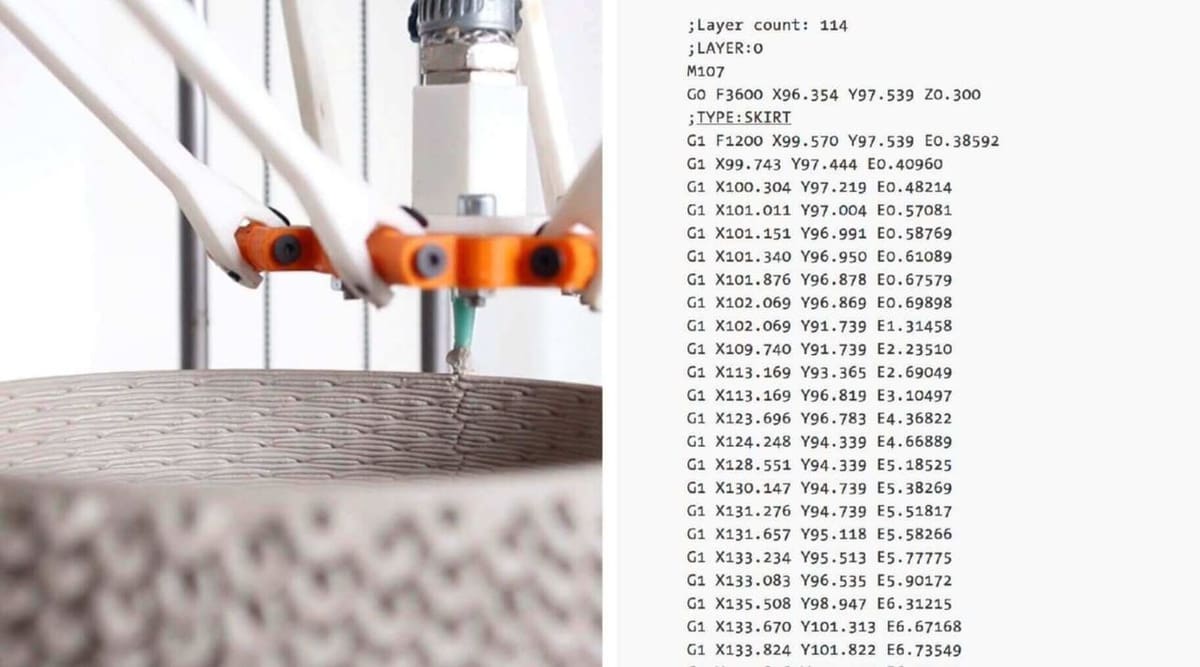
At its simplest, G-code is a list of instructions that tells a 3D printer what to do. A G-code file contains commands for actions such as moving the printhead, extruding filament, heating the nozzle and bed, and controlling the cooling fans. The printer works through these instructions in sequence to produce the finished part.
G-code isn’t unique to 3D printing. It originated as a way to control computer numerical control (CNC) machinery and is still used with equipment such as mills, lathes, laser cutters, and other computer-controlled machines. In 3D printing, however, the commands are tailored to the movements and functions needed to build an object layer by layer.
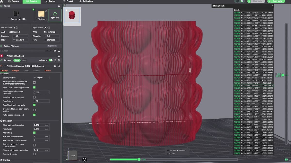
You usually don’t need to create these instructions yourself. When you slice a 3D model, the slicer converts your settings and the model’s geometry into a G-code file that your printer can understand. A typical print can contain thousands or even millions of individual instructions, which is one reason slicers handle the heavy lifting for us.
Despite the name, not every instruction begins with a “G”. The commands you’ll encounter most often fall into two broad groups. G-commands generally deal with movement and positioning, including moving the printhead and extruding filament. M-commands usually control other printer functions, such as temperatures and fans.
For example, a command might tell the printer to move to a particular position, while another tells it to heat the nozzle to 210 °C. Once you understand how these individual instructions are put together, a G-code file starts looking much less like a wall of code and more like a step-by-step description of what your printer is doing.
The Syntax
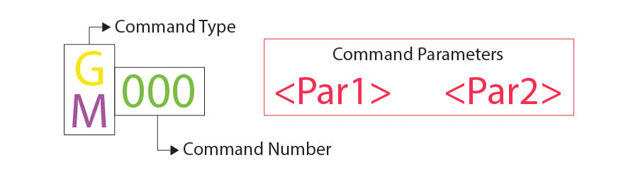
Every G-code command line generally follows a certain syntax, and as a beginner-friendly rule of thumb, each line corresponds to only one command, which can lead to codes that are awfully lengthy. That’s not a hard restriction, though. Marlin itself documents combinations like G53 G0 X0 Y0 Z0, where more than one G-word appears on the same line, and Klipper goes further still with extended commands that don’t fit this simple G/M<number> parameters pattern at all.”
The first argument of any given line is the command code itself. As we have seen, it can be either a ‘G’ or an ‘M’ code type, followed by a number that identifies the command. For instance, “G0” corresponds to a linear move command.
Next comes the parameters that more accurately define the command. For a G0 linear move, these parameters include the final position and how fast it moves, also identified by upper-case letters. Each command has its own set of parameters as we’ll see soon.
A Note on G-code Comments
Before we get started, when we go over the various commands, you’ll see semicolons after a letter and number that explain what the code does. Here’s an example of a line that has a code comment:
G1 X25 Y5 ; I am a code comment!Programmers often need to include explanations in plain English so that other programmers can understand certain lines or sections of code. It might also happen that you forget why you coded things in a certain way, resulting in a difficult time figuring things out again.
Code comments solve this problem. They can include anything (on the same line) following a semicolon and are completely ignored by the machine when it executes the G-code. In this way, they are purely meant for programmers’ eyes.
Why Would You Edit G-code Yourself?

Everything covered above happens automatically. Your slicer reads your 3D model, works out the layers and toolpaths, and writes all the G-code for you. Most people never need to look at a single line of it, so why would you ever want to open that file and touch it yourself?
The most common reason is customizing your start and end sequences. Nearly every slicer gives you an editable box for “custom start G-code” and “custom end G-code”. This is exactly what the Initialization and Reset phases covered later in this article are made of. People use these to add a priming line before printing begins, trigger a specific bed-leveling routine, fire off a camera for timelapses, or make sure everything shuts down safely once a print finishes.
Another reason is doing something your slicer’s interface doesn’t offer a button for. A classic example is a manual filament change: inserting an M600 command at a specific layer height to pause the printer and swap colors partway through a printan, even on a printer with just one nozzle. Worth noting: M600 isn’t a universal G-code command. On Marlin, it only works if the firmware was compiled with the Advanced Pause feature enabled and it’s not on by default everywhere. Klipper doesn’t support M600 natively at all; Klipper users typically get the same pause-and-change behavior through a custom gcode_macro M600 rather than a built-in command.
Example:
M600 ; pause the printer and prompt a filament changeDropping that single line into the file at the right point (usually found by searching for a specific layer-change comment) is often easier than trying to configure the same effect through the slicer’s own settings.
Sometimes it’s about fixing one specific problem rather than re-slicing everything. If you notice your slicer generated a bad travel move that’s causing stringing on just one part of a model, editing that one line directly can be faster and safer than changing a global setting and hoping nothing else breaks.
There’s also a semi-automated version of all this: post-processing scripts, which slicers like Cura and PrusaSlicer support directly. Instead of manually editing a file by hand, these scripts rewrite the exported G-code automatically for a specific purpose, from adjusting fan speeds layer by layer to converting flat toolpaths into non-planar ones.
If you want to go further and test commands directly, rather than editing a file, that’s covered in Terminal Inputs & Outputs, later in this article, along with a few things worth knowing before you start typing G-code in from an unfamiliar source.
Important Commands for 3D Printing
As there are literally hundreds of G-code commands, we’ll cover the most basic and important ones in the following sections. Once you get the hang of it, you’ll be able to explore other commands from reference sheets on your own.
G0 & G1: Linear Motion
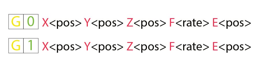
The G0 and G1 commands both perform linear movements. By convention, G0 is used for non-extrusion movements like initial and travel moves, while G1 encompasses all the extruding linear motion.
Both commands function the same, though. The parameters for G0 or G1 include the final positions for all the X-, Y-, and Z-axes, the amount of extrusion to be performed during the move, and the speed, specified by the feed rate in the set units.
Example
G1 X90 Y50 Z0.5 F3000 E1 tells the printer to move in a straight line (G1) towards the final coordinates X = 90 mm, Y = 50 mm, Z = 0.5 mm at a feed rate (F) of 3,000 mm/min while extruding (E) 1 mm of material in the extruder.
Most linear moves are performed within a single layer, meaning that the Z coordinate is usually omitted from the command line.
It’s also worth knowing that G0 and G1 aren’t the only motion commands out there. G2 and G3 handle clockwise and counterclockwise arc moves. For most of 3D printing’s history these rarely showed up, since slicers just approximated curves using lots of short G1 segments instead. That’s changed somewhat: current versions of slicers like PrusaSlicer and OrcaSlicer can generate native G2/G3 arc moves instead (often under a setting called ‘arc fitting’), which can shrink file size and smooth out curved surfaces. We won’t get into their syntax here, but it’s worth recognizing them if you spot G2/G3 in a sliced file.
G2 X95 Y55 I5 J0 E0.4 F1200 tells the printer to move in a clockwise arc (G2) to X = 95 mm, Y = 55 mm, extruding (E) 0.4 mm of material along the way, at a feed rate (F) of 1,200 mm/min. The I5 and J0 define where the arc’s center sits — 5 mm to the right and 0 mm up from the nozzle’s current position, not from the destination point.
G90 & G91: Absolute & Relative Positioning
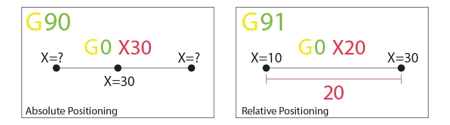
The G90 and G91 commands tell the machine how to interpret coordinates used for movement. G90 establishes “absolute positioning”, which is usually the default, while G91 is for “relative positioning”.
Neither command requires any parameters, and setting one automatically cancels the other. The way positioning works is quite simple, so let’s jump right in.
Example
Let’s say we want to move the printhead to X=30 in a line. In absolute positioning mode, that would look like this:
G90 ; sets absolute positioningG0 X30 ; moves to the X = 30 coordinate
So, for example, the line of code would be:
G90 G0 X30This simple move would tell the printer to move the printhead so that it’s positioned at X = 30. Now, for a relative positioning move, we need to know where the printhead is currently. Let’s assume it’s at X = 10:
G91 ; sets relative positioningG0 X20 ; moves +20 mm along the X-axis
In this instance, the line of code would be:
G91 G0 X20
G91 first tells the machine to interpret the coordinates as relative to the current position (X = 10). Knowing that, the machine simply needs to move 20 mm in the X-axis positive direction, thus reaching X = 30, as we’d like.
One nuance worth flagging: G90/G91 govern X, Y, and Z movement, but the extruder (E axis) can be switched onto its own separate mode using M82 (absolute extrusion) and M83 (relative extrusion), independent of whatever G90/G91 is doing.
Example:
G90; sets absolute positioning for X, Y, ZM83; sets relative extrusion for E, regardless ofG90aboveG1 X30 E5; moves to X = 30 (absolute), while extruding 5 mm more filament (relative)
This matters in practice because plenty of current printers default to exactly this combination: G90 for the toolhead, M83 for the extruder. If you’re writing or editing custom G-code by hand, don’t assume E behaves the same way X/Y/Z does; check which extrusion mode is actually active first.
G28 & G29: Auto-Home & -Bed Leveling
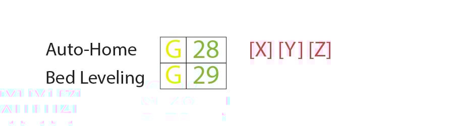
We call “homing” the process of setting the physical limits of all movement axes. The G28 command will perform this task by moving the printhead until it triggers endstops to acknowledge the limits.
Worth noting: ‘endstops’ doesn’t always mean a physical switch anymore. Plenty of current printers use ‘sensorless homing’ instead, where the stepper driver detects the motor stalling against the frame through a small current spike, rather than tripping a mechanical switch. It’s especially common on DIY builds and budget machines, since it skips the extra wiring a physical switch needs.
Homing is important not only for the machine to orient itself but also to prevent the printhead from moving outside the boundaries. The G28 command is usually performed before every print process.
Another command, G29, starts the automatic bed leveling sequence. There are many different methods for leveling a bed prior to printing, as this is usually set by firmware and not by the final users. For this reason, we won’t get into details surrounding the methods and command parameters. Just know that G29 is usually sent after an auto-home (G28) and should perform the automatic bed leveling as determined by the firmware.
One firmware-specific wrinkle: this matches how Marlin handles things. Klipper doesn’t use G29 natively for bed leveling; it relies on a macro called BED_MESH_CALIBRATE instead. Many Klipper setups still map G29 to that macro for compatibility with slicer-generated files, but if you’re troubleshooting a Klipper-based printer directly, BED_MESH_CALIBRATE is the name to actually look for.
Example
G28 X Y ; home the X and Y axes onlyG28 ; home all axes
Specific axis can be individually homed by including X, Y, or Z as parameters. Otherwise, G28 alone will home all three.
G29 ; perform automatic bed leveling sequenceIf you want to run an auto-bed leveling sequence, remember to send G29 after performing the homing process.
M104, M109, M140, M190, M141, & M191: Set Temperature
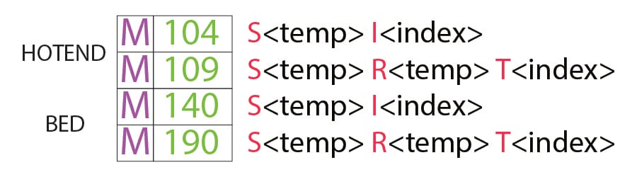
These are essential miscellaneous commands, which again, don’t involve any motion.
To start, the M104 command sets a target temperature for the hot end to reach and keep it until otherwise instructed.
Some of the parameters include the actual temperature value (S) and which printhead (T) to heat (for multiple extrusion setups).
Example
M104 S210 ; set target temperature for hot end to 210 degreesThis command line instructs the machine to heat up its hot end to 210 °C and assumes that there’s only one hot end in this extrusion setup. After setting the target temperature, the printer will go on to perform the next command line while heating the hot end.
Alternatively, if we wanted to wait until that target is reached before moving on to the next line, we can use the M109 command.
M109 S210 ; set target temperature for hot end to 210 degrees and do nothing until reachedSetting the bed temperature is very similar to the hot end, but instead with the M140 and M190 commands:
M140 S110 ; set target temperature for bed to 110 degreesM190 S110 ; set target temperature for bed to 110 degrees and do nothing until reached
There’s one more temperature zone this doesn’t cover: the build chamber. If you’re on an enclosed printer, M141 and M191 work exactly the same way as M140/M190 do for the bed. M141 sets a target chamber temperature and moves on, while M191 pauses until that temperature is actually reached.
M141 S40 ; set target temperature for chamber to 40 degrees
M191 S40 ; set target temperature for chamber to 40 degrees and do nothing until reached
M106 & M107: Fan Control
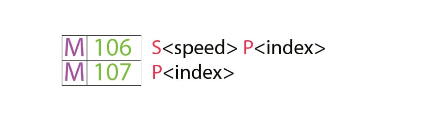
Yet another essential task for 3D printers, the miscellaneous M106 and M107 commands provide fan control.
M106 turns a fan on and sets its speed. This is especially useful for the part cooling fan, as different speeds are required when printing the first layer and while bridging.
The speed parameter must be a value between 0 and 255. A 255 value provides 100% power, and any number within this range will specify a percentage accordingly.
That 0–255 scale is how Marlin handles it. Klipper’s native fan control actually runs on a 0.0–1.0 scale internally, though it still accepts standard M106 S-values in the 0–255 range for compatibility with sliced files, so nothing changes about how you’d write it, but it’s worth knowing if you ever go looking at Klipper’s own fan commands directly
Example
M106 ; turn on a fan at maximum (100%) speedM106 S128 ; turn on a fan and set it to 50% power
Multiple speed-controlled fans can be defined by the index (P) parameters, as each fan is assigned an index by the firmware.
A concrete example of why that matters today: enclosed printers commonly run a separate auxiliary or exhaust fan, often used to filter fumes when printing materials like ABS or ASA, alongside the standard part-cooling fan, each controlled the same way via M106/M107 but assigned a different P index
Finally, the M107 command will power off a specified fan. If no index parameter is provided, the part cooling fan is usually the one to be shut down.
Program Structure
We’re now in a good position to look at an actual piece of code that’s used for 3D printing. G-code programs can be divided into three distinct sections, as we’ll see next.
It’s worth noting that, if you use a text editor to open a G-code file generated by a 3D slicer, it might be that it won’t immediately start with G- or M-commands. For example, a slicer like Cura or Orcaslicer starts code by including some of the printing process parameters defined previously within comments. These lines won’t affect the printing but instead present a quick reference for parameters like layer height, for example.
Phase 1: Initialization
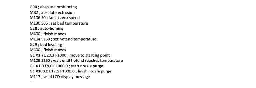
The first section of any program includes the preparation tasks required prior to starting the printing of the model. The following are the first six lines of initialization G-code commands from an actual 3D printing job:
G90 M83 M140 S80 M104 S200 G28 G29As we now know, the first line says that movements should use absolute positioning, while the second line tells the extruder to interpret extrusion in relative terms instead, the default on most current printers.
Same structure, same effect on X/Y/Z — just relative extrusion instead of absolute for that second command
The third and fourth lines start heating the bed and nozzle to their target temperatures. Note that it won’t wait for the target temperature, meaning that the printer will auto-home and level the bed while heating up.
Some initialization routines (e.g. the one used by PrusaSlicer) include a nozzle purging process, like printing a single straight line before jumping into the printing process.
Phase 2: Printing
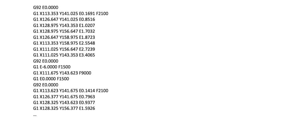
Here’s where the magic happens. If you look at a sliced G-code file, you’ll see that it’s impossible for us to make out what the nozzle is actually doing.
3D printing is a layer-by-layer process, so you’ll find that this phase includes many movements within the XY-plane while printing a single layer. Once that’s done, one tiny movement in the Z direction will define the beginning of the next layer.
Here is an example of how G-code commands can look during the printing phase:
G1 X103.505 Y153.291 E4.5648 ; movement and extrusion in XY planeG1 X103.291 Y153.505 E4.5804 ; movement and extrusion in XY planeG1 Z0.600 F3000 ; change layerG1 X104.025 Y154.025 F9000 ; movement in XY planeG1 X95.975 Y154.025 E0.4133 F1397 ; movement and extrusion in XY plane
Keep in mind this example only shows G1 moves. On a file sliced with arc fitting turned on, you’d also see G2/G3 arc moves mixed in here, working the same way we covered earlier.
Phase 3: Reset the Printer
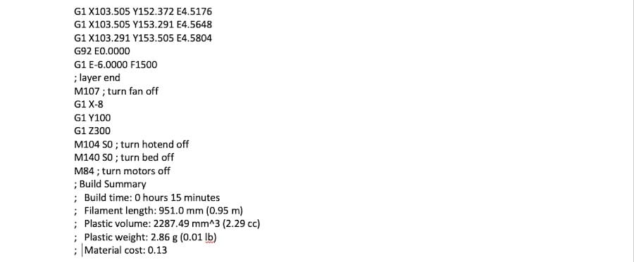
Finally, when printing is done, some final lines of G-code commands bring the printer to a reasonable default state.
For example, the nozzle might go to a pre-defined position, the hot end and bed heaters are turned off, and the motors are disabled, among other actions.
M107 ; turn fan offG1 Z10 ; move nozzle away from printM104 S0 ; turn hot end heating offM140 S0 ; turn bed heating offM84 ; turn motors off
On an enclosed, heated-chamber printer, you’d typically see one more line in there, turning off the chamber heater alongside the hot end and bed:
M107 ; turn fan off G1 Z10 ; move nozzle away from print M104 S0 ; turn hot end heating off M140 S0 ; turn bed heating off M141 S0 ; turn chamber heating off M84 ; turn motors offTerminal Inputs & Outputs
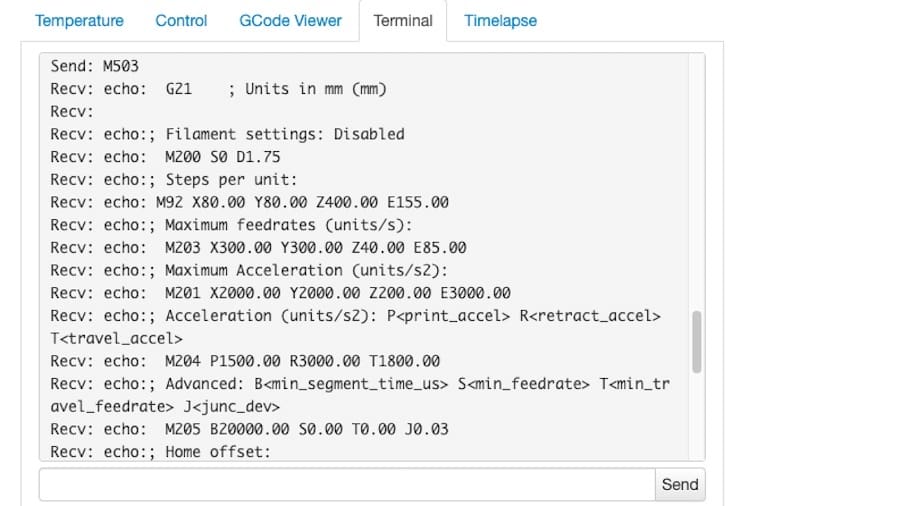
Until now, we’ve only talked about the computer sending G-code commands to the printer (usually transferred over WiFi, USB, or an SD card). However, this isn’t the only method of communication.
Some control software, like Pronterface and OctoPrint, allows direct communication with the 3D printer, in which case you can input commands manually.
For obvious reasons, it wouldn’t be practical to print anything by sending lines of codes individually. But sometimes this method of communication is needed for other purposes, like retrieving valuable information for calibration or even when the 3D printer lacks a display screen.
For example, the M105 “report temperatures” command will retrieve the current nozzle and bed temperatures (which might then be displayed by something like OctoPrint).
This communication is also very useful for seeing and changing EEPROM settings that are hardcoded at the firmware level. Parameters like a motor’s steps/mm, maximum feed rates, or PID can be visualized via M503 (“report settings”), changed manually, then saved via M500 (“save settings”).
One more thing worth knowing before you start typing commands directly into a terminal: not every line of G-code is harmless just because it looks simple. Security researchers published findings in 2025 cataloging hundreds of ways a malicious or mishandled G-code file could cause real problems, from leaking information to permanently misconfiguring a printer. That’s mostly a concern for G-code you didn’t write yourself (a downloaded file, a shared script), not commands you’re typing in to check your own settings, but it’s a good reason to think twice before pasting in G-code from an unfamiliar source.
Writing G-code
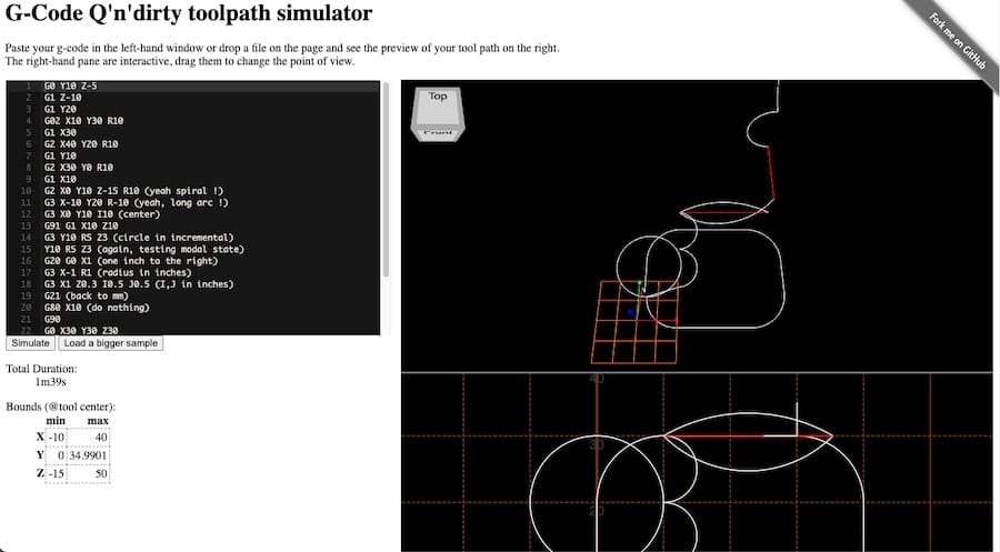
By now, you should be able to read and understand G-code much better. Still, you can also benefit from writing it.
This NCViewer is a great tool for testing your skills, as you can write G-code commands and simulate them accordingly, and turns out to be an enjoyable project.
Looking at exported G-code files from slicers should also provide you with some insights as to how G-code works for 3D printing. Make sure to have a commands reference sheet by your side and explore the code.
Compatibility
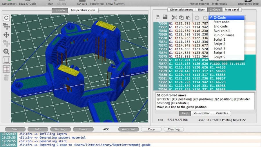
Understanding G-code can make you a more confident and capable 3D printing user, but there’s one last thing to keep in mind: not every printer speaks exactly the same version of it.
Different firmware, such as Marlin, RepRap, and Klipper, can use different G-code “flavors”. A command that works on one machine may behave differently – or not work at all – on another. Your slicer usually takes care of this by generating G-code for the firmware selected in your printer profile.
You’ve already seen examples of these differences in this guide. Klipper, for instance, uses BED_MESH_CALIBRATE for bed leveling instead of G29, and handles fan speeds differently from Marlin.
So, while you don’t need to memorize every command, knowing how to read G-code – and when firmware matters – can make troubleshooting, tweaking, and understanding your printer much easier.
With that said, we hope you enjoyed this brief guide. Happy coding!
You May Also Like:
License: The text of "3D Printer G-code Commands: What They Do & the Small Tweaks That Make Prints Better" by All3DP is licensed under a Creative Commons Attribution 4.0 International License.