3D Printing Troubleshooting Guide: 30 Common Problems & Solutions

All3DP's complete 3D printing troubleshooting guide, including many common FDM 3D printing problems and solutions, tips, and tricks to fix them.
We’ve had our fair share of print mishaps here at All3DP, leading us to many hours, days, months, and years trying to wrap our collective heads around the causes and solutions for common 3D print issues
The following guide is our collective work to help you diagnose and fix common 3D printing problems involving FDM technology.
A note on using this guide: There is no such thing as a definitive troubleshooting guide for 3D printing. This guide isn’t, nor will it ever be. What it is, though, is a pooled collection of tips, suggestions, and avenues of investigation we know from our experiences, plus common knowledge in the 3D printing space. There’s always room for more, so let us know your issues that fall outside this guide in the comments, and we’ll investigate them for future updates.
Try to think of this guide as a starting point to help orient you and set you on a path to a possible solution to your problem. It’s up to you to consult your manufacturer’s documentation for detailed instructions where necessary.
Use the links below to narrow your search for a solution or the table of contents to jump directly to a particular issue, its causes, and solutions.
FDM 3D Printing Problems
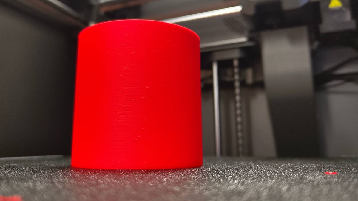
Editor's note: Kudos to the Prusa MK4/MMU3 we used through testing for this guide. It bounced back from every act of sabotage we enacted to prod and probe these printing issues and gather fresh photos. The MK4 is out of production now, but we expect its sucessor, the Original Prusa MK4S, would fare just as well.
Get our bi-weekly newsletter for the latest 3D printing news, deals, and guides.
We do not share your information! You can unsubscribe at any time.
By subscribing you agree to our Privacy Policy.
First Layer Problems
Extrusion Won't Stick to the Bed
Molten plastic extrudes from the nozzle but doesn’t stick to the print bed. What gives?
There are a few simple things to check for this particular issue.
Causes
Improper Z-offset / Nozzle Too Far From the Print Bed
You need molten filament to “squish” slightly into the print bed in order to produce a good first layer. If your Z-offset – the distance between the nozzle opening and the print bed surface – is too large, too little or even no contact at all is being made. The filament won’t stick.
Insufficient Adhesion
If your offset is fine, but the filament still doesn’t stick, then adhesion is likely to be your issue. Many modern print beds are suitable for materials like PLA, relying on mechanical adhesion to grip the plastic. Other materials, however, in combination with your particular print bed material, may require a layer of adhesive to ensure the plastic sticks.
Too Much Adhesive
It’s possible to have too much adhesive, though, particularly if you have regularly reapplied adhesive between prints. This is too much, particularly with PVP-based adhesives like glue sticks, which can lose their efficacy sticking to the filament as a thick, dried-out layer.
Contaminated Print Bed
Molten filament sticks best to a clean, contaminant-free surface (the only exception to this is a thin layer of adhesive). Even handling a PEI-type print bed with bare hands can transfer natural skin oils onto the surface and interfere with the filament’s ability to stick.
Solutions
Relevel your bed / Adjust Z-offset
Finding the nozzle-bed sweet spot will see your extrusions go down on the bed evenly and smoothly.
If your printer offers any form of “automatic bed-leveling,” you can skip this step.
In your printer’s Z-offset setting, sometimes also found under “level” or “bed level” named menu options, adjust the value in small increments until you have closed the distance and the filament gets a good “squish” on the bed. You can use a sheet of paper between the nozzle and bed to estimate this – aim to have the paper barely trapped by the nozzle, free to move but with some resistance.
You can also test this live during a print if your printer allows for live Z-offsetting. Set a print running and, using the live Z-offset option in the printer’s menu, adjust the nozzle gap until it’s close enough for the filament to squish and stick.

Clean your print bed
Fingerprints and the general build up of grime can prevent the filament from sticking to your print bed. Figure out the appropriate cleaning regimen for your particular print plate in order to keep it in filament-gripping shape. Check your printer’s documentation to see the bed material that came with it.
Note: While detergents usually work, you can also use some solvents to clean a print bed. Some solvents can damage your print bed though – check the compatibility before using.
Use soapy water to clean PEI-coated print beds – a common type of bed usually identifiable by a vaguely golden color. Thoroughly rinse off the bed to remove any residual soap, as it can also cause poor adhesion. A light spritz of isopropanol alcohol (IPA) on a paper towel can help to keep a PEI plate in good shape between deep cleanings. Do not use acetone to clean a PEI print surface.

Apply a thin layer of adhesive to your (clean) print bed
It’s usually enough to have a clean print bed for decent adhesion with PLA. Other materials benefit from a thin layer of adhesive (not only to help the filament stick, but also to stop it from sticking too much). Regular glue sticks work well, but you can also buy specialized print-specific adhesives such as Dimafix and Magigoo, which apply and wash off easily and provide great adhesion.

Rough it up
This tip only really applies to smooth polymer-based print surfaces. In the long haul, a smooth, well-used print bed may lose some of its grippiness. You can restore it by gently and methodically roughing the surface with a melamine sponge (Magic Eraser). It’s like using extremely fine-grit sandpaper, but easy to handle and, possibly, you already have one sitting around with your household cleaning supplies.
Gaps in the First Layer
A good first layer should be seamless and smooth. Some (but not all) gaps between the extrusions, the infill, and the wall of the first layer could indicate a problem that could propagate issues to other areas of the print.
Causes
Improper Z-offset / Nozzle too far from the print bed
A good first layer requires the right amount of “squish” on the filament, spreading the extrusion wide enough to fill the path of the toolhead with minimal gaps between parallel lines.
If the effect is inconsistent across your bed, it’s possible the bed is not level, or the mesh your mesh bed probe generated does not accurately apply across the bed surface.
First layer print speed is too fast
A print speed that starts too fast does not allow sufficient material to settle on the print bed, particularly if your Z-offset is not perfect.
Solutions
Re-level your bed / adjust Z-offset
Finding the nozzle-bed sweet spot will see your extrusions go down on the bed evenly and smoothly.
If your printer offers any form of “automatic bed-leveling,” you can skip this step.
One solution is dialing the nozzle distance. If you only see gaps between extrusions in certain areas of the print bed, then re-leveling the bed or running the bed mesh routine may help.
When this issue is present across the entire first layer, it suggests a level bed but improper Z-offset. Adjust it by small increments while a print runs to observe the difference.
Set a lower first-layer print speed
Find the settings for print speed in your slicer and look for one that specifically controls the bottom layers. In some slicers this is presented as a global setting for both top and bottom layers. By default this speed will be lower than your general printing speed, but if you’re certain your bed is level and that’s not at fault, lowering this speed slightly may help.
Note: It is normal for there to be tiny gaps in the tighter angles and around features in your first layer. It may not be possible to 100% eliminate these; focus instead on the parallel lines and them meeting the walls of the print.
Waves in the First Layer
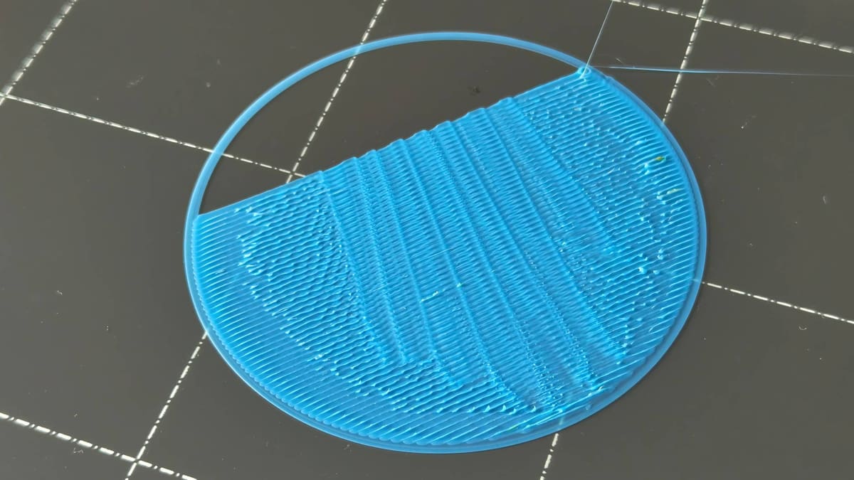
Curling first layers with the appearance of breaking waves can rapidly ruin a print. Thankfully, there’s an easy solution.
Causes
Nozzle too close to the bed
Your printer extrudes a calculated amount of filament to fill a given gap between the nozzle and previous layer or, for the first layer, print bed. If the nozzle is too close, the plastic is forced into adjacent areas which subsequently have poor adhesion. This compounds across the layer, resulting in the appearance of waves that run parallel to the direction of the extrusion.
Solutions
Reset/Adjust your nozzle offset
Older printers may require you to physically adjust the print bed, lowering the four corners in order to increase the nozzle offset. That, or repositioning the Z endstop. Newer printers usually let you do this in the software using the Z-offset setting on the printer’s display. Your objective is, in whichever way, to increase the distance between your printer’s nozzle and the print bed. Make sure you pay attention to how your printer presents this, as it could be the case that the positive and negative values are doing the opposite of what you assume.
Many newer printers, including those by Bambu Lab, do not let you manually adjust the printer’s Z-offset in the ways described above. It’s unlikely that the Z-offset is your issue with such printers, since their first-layer calibrations are generally very good.
Check your slice
We’ve printed enough over the years to know that many printing issues come from oversights when preparing a print job in the slicer. Improper parameters such as nozzle sizes and line widths, or even the wrong material selection, can cause problems. If you’ve gone down a rabbit hole fiddling and adjusting settings without keeping track of the cumulative changes, resetting to the default settings and starting fresh can give you a quick, fresh starting point build from.
Print Bows Out at Bottom (Elephant's Foot)
A classic 3D printing issue with a funny name, “Elephant’s Foot” is a catch-all term given to the undesired spread of the first few layers of a print.
Causes
Improper bed level / Z-offset
If your nozzle is too close to the bed for the first layer of your print, you will end up with a over-compression of plastic in the first few layers. As the print progresses, the distance and plastic inhabiting a layer equalizes. More warm plastic in a smaller space that is continuously built on top of only has one direction to go, and that’s out.
Improper bed temp
Materials with lower printing temperatures (such as PLA) don’t necessarily need a heated bed to print successfully. To help mitigate warping, a heated bed can help, but printing with the bed temp too high may result in the lower layers remaining just warm enough to spread slightly as the mass of the print above it increases.
Consequence of initial layer settings
Sometimes it can simply be the case that your first layer’s squish onto the print bed flares a little more than it should.
Solutions
Relevel your bed / adjust Z-offset
Double-check to see that the nozzle gap for your first layer is the best it can be.
If your printer offers any form of “automatic bed-leveling,” you can skip this step.
Having leveled and offset your bed according to your manufacturer’s instructions, in our opinion, there’s no better method to fine-tune this further than to run a single-layer print that covers a large area of the print bed. In this case, covering the area of the bed where the elephant’s foot is for you.
Tip: The term "Leveling" can mean a few different things, from physically adjusting the corners of a manually leveled bed, to running mesh bed leveling, where your printer measures and compensates differences in the surface of your bed.
As the model prints, use your live Z-offset option to fine tune your nozzle gap, aiming for smooth, even extrusions that meet wall-to-wall with no ripples or bunching of the filament.
Slicing compensation
There are in-slicer settings to compensate against elephant’s foot. Setting a value here will shrink the initial layers by a small amount and level off this first layer spread. Most slicers default with this option active; this setting does not fix an improper Z-offset, though it is a quick fix on a print-by-print basis.
Here’s where to find elephant’s foot compensation in three popular slicers:
- Cura: Go to “Walls” (Custom mode) > “Initial Layer Horizontal Expansion”
- PrusaSlicer: Go to “Print Settings” (Advanced mode) > “Advanced” > “Slicing” > “Elephant’s Foot Compensation”
- OrcaSlicer: Go to “Quality” (Advance mode) > “Precision” > “Elephant’s Foot Compensation”
Print Edges are Bending (Warping)
Printed plastic can warp as it cools. Most of the time this is not an issue, as the structure and gradual pace at which it cools keeps the warp at bay. Sometimes the shape of a print and the material used can win out however, with parts (or even the whole print) curling free from the print bed.
Causes
Improper cooling
First layers require little-to-no cooling in order to guarantee a print adheres properly to the bed. Getting the print to solidify quickly takes a backseat to letting the extruded plastic anchor itself to the print bed. Too much cooling this early on can compromise a print’s bed adhesion.
Improper bed level / Z-offset
Adhesion is key, and a first layer that doesn’t have sufficient “squish” can cause all kinds of problems later in a print. Therefore, an improper nozzle-bed gap can be the culprit for prints warping free from the bed.
Sharp features in the design
Warping is exacerbated by uneven cooling in your print. Sharp, thin features and edges on the first layer of a print cool much quicker than larger bodies and so are particularly susceptible to warping.

Solutions
Add glue
While glue shouldn’t be necessary in most cases with a properly leveled bed and clean print surface, sometimes, it does help. Water-soluble PVP glue sticks are a staple, but you may also have success with hairspray. Popular printing-specific adhesives like Dymafix and Magigoo work well too.
Re-level your bed / adjust the Z-offset
The “have you tried turning it off and on again?” of 3D print troubleshooting. Fine-tuning the gap between your nozzle and bed leads to better first-layer adhesion and, consequently, less chance of warping on otherwise unchallenging prints.
Double-check that the nozzle gap for your first layer is the best it can be.
If your printer offers any form of “automatic bed-leveling,” you can skip this step.
Turn off cooling for the first couple of layers
Consider turning off print cooling entirely for the first few layers of your print. This setting is commonly found in the material-specific settings menu of your slicer.
Add adhesion aids
If you can stand a little post-processing, consider adding one of the many adhesion helpers available in the settings of your slicer. Brims and rafts are effective against warping.
A brim extends from the outline of the first layer of your print. While it gives a larger surface area to help pin your model down, sharp features will likely still fail even with a brim.
Choosing a raft will add a dense raft of material beneath your print, with your model printing on top. This method of print adhesion uses the most material and sacrifices some print quality (if you care about getting the silky smooth imprint of your print bed) but does a generally good job of mitigating warp. A raft will be less effective if your Z-offset is poor, since the raft needs to effectively adhere to the bed before your model prints on top of the raft.
Alternatively, consider adding disk-like pads at the tip of sharp features. These sacrificial parts of a print exist only to anchor thin parts of a print to the bed, and can be snipped away with flush cutters later.
Note: Not all slicers include pads as an option, so you may have to add them manually yourself. Be sure to make them only a few layers thick so they're easy to remove.
My Print Looks Bad
Infill Looks Messy and Incomplete
The printing process is broken down into many different phases and components by your slicer, with the print behaving different for each unique part of a layer. An outer wall prints slower, for better quality, while the infill will typically go down quicker with less care for visual appearance. Messy infill, however, can become a problem and cause issues later in your print, with the risk of collisions and your print coming free from the bed.
Causes
Printing too fast
All filaments behave differently, and most printer profiles and materials settings are set to be generally suitable. Sometimes the printing of the infill goes a bit faster than the hot end can handle or fans can cool, resulting in untidy infill that can shear away and stick up above the surface of the print.
Solutions
Lower infill print speed
Navigate to your slicer’s speed settings and lower the infill print speed. There’s no fixed rule for this, so experiment with small, incremental values.
Gaps Between Walls / Shells
When printing with multiple walls (outer layers), they should be seamless for dimensional accuracy and strength.
Causes
Improper print settings
There are a number of settings that could cause such an effect, but one easy-to-diagnose combination is too low a print temperature paired with too high a print speed.
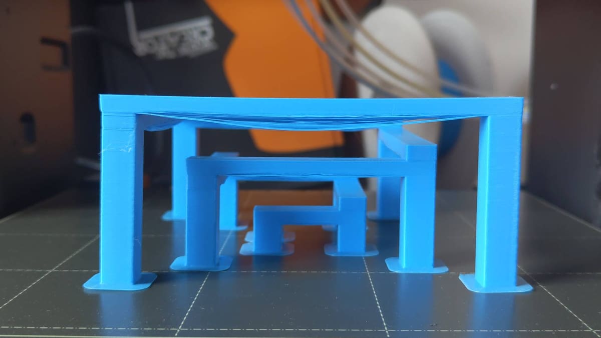
Backlash / loose belts
If the gaps in your walls are asymmetrical, or confined to only one axis, then it’s possible that there is some play in the motion system. The print head is not travelling to exactly where it needs to be to accurately lay down the walls parallel and uniform.
Under extrusion
Walls not sticking to each other can also be a subtle sign of under extrusion. Not enough filament is being put down to fill out what the slicer has allocated to fill that particular gap.
Solutions
Check for backlash / tighten belts
On cantilever and bed-slinger style 3D printers, the belts for the print head and bed’s motion should be tight enough that they stiffly resist you pinching them together, but not so tight that it requires a lot of force to do so. Alternatively, after disabling your printer’s stepper motors, pinch one particular section of the belt, draw it back and forth and observe the print head (or bed, whichever applies) to see if there’s any slop in the movement. There should be a direct transmission of movement.
Some printers feature belt tensioners at the end of each belt’s respective gantry arm. These typically require you to take an Allen key and tighten a machine screw, which shifts the idler and increases the tension. Other printers have thumbscrews for you to turn to tighten the belts.
CoreXY-style printers offer different ways to tension the belts. Consult the manufacturer’s instructions for guidance on how to safely do this without compromising the printer’s performance.
Note: Overtightening the belts can make it harder for your motors to move the bed and print head, resulting in suboptimal performance.
Increase print temperature / lower print speed
Increasing your filament’s ability to flow with a slightly higher print temperature or lowering the shell/wall print speed will allow the wall extrusions to make better contact. Only increase the temperature if you know that it falls within the manufacturer’s recommended range.
Gaps Between Infill and Walls
Vital for dimensional stability and strength, the transition from the infill to the outer walls of a print should be seamless.
Causes
Print temperature too low / infill printing too fast
All materials come with a suitable printing temperature range. While it’s generally advisable to print as cool as you can with a given material, some may not flow as well as the slicer assumes. Your nozzle choice may impact this, too, with steel nozzles in particular susceptible to poor thermal conductivity and not being quite as hot as the printer thinks it is.
Similarly, the preprogrammed infill print speed for your material may result in not enough filament being extruded to make the solid connection.
Both of these causes are, effectively, causing underextrusion of a sort. Not uniformly, in the way a blocked nozzle might, but enough to impact this specific facet of a print.
Insufficient infill overlap
Depending on your particular material and print, it could be that your infill doesn’t quite buddy up to the walls of your print. This is a numerical value in your slicer, which can be increased to ensure more contact between the infill and walls of your print.
Solutions
Increase print temperature
Experiment with small temperature increases (5 °C at a time) could help you see the infill anchoring into the wall properly. This, of course, should be tempered against the general recommended temperatures for your material.
Reduce infill print speed
Similar to the solution above, addressing minor underextrusion in the infill could be tackled with slight print setting adjustments, such as reducing the infill speed. Typically found in the “advanced” area of your slicer’s settings for your print “quality” profile, dialling the infill speed (in some slicers, “sparse infill” speed) back marginally may see improvements in the connection between infill and walls.
Increase infill overlap percentage
Navigate to the setting in your slicer that controls infill overlap percentage. Many slicers express this as a percentage of the wall width and have it set at zero by default. Test this value by incrementally increasing the percentage between test prints.
Note: Make sure to disable the top layers of your test print, or program a pause part-way through the print so you can observe where the infill and walls meet.
Corner "Flare"
Anyone who has printed an XYZ calibration cube has likely seen this issue. What should be a clean 90-degree angle in the print inexplicably bulges at the corner. This 3D print error has one cause, but multiple possible solutions. Picking one appropriate for your printer is key.
Causes
Over extrusion at direction / speed changes
Too much filament is extruded as the printhead approaches a direction change, slowing and then speeding up as it goes.
Solutions
Recalculate pressure advance
Your printer may have a calibration routine titled something like “auto flow rate compensation”. While it’s highly unlikely that your flow values will suddenly be bad, running this auto-calibration may be a quick fix for corner flare on your prints.
Your printer’s slicer may also offer manual pressure advance calibration – a set of test prints for you to measure against and adjust your slicer’s settings for a given filament. In Bambu Studio (and Orca Slicer and Super Slicer, both of which the former is partially based on) this calibration test can be found in the “Calibration” tab of the slicer.
Explore our deeper dives on pressure advance / linear advance for Marlin and Klipper for a comprehensive view of this particular firmware trick and how to implement it with your printer if it doesn’t already offer it.
Lower your print speed
If your printer lacks linear advance (pressure advance) calibration settings, your next bet should be to lower your outer wall print speed a little. You may be printing faster than your printer can effectively cool at direction changes, resulting in deformation.
Increase your print cooling
Similar to the print speed suggestion above, increasing the efficacy of your print cooling may be needed. Check your filament profile in your slicer to see how strong your cooling is set to run during the print. PLA benefits from strong cooling, PETG less so; blipping the cooling a little higher may help for dimensionally iffy prints.
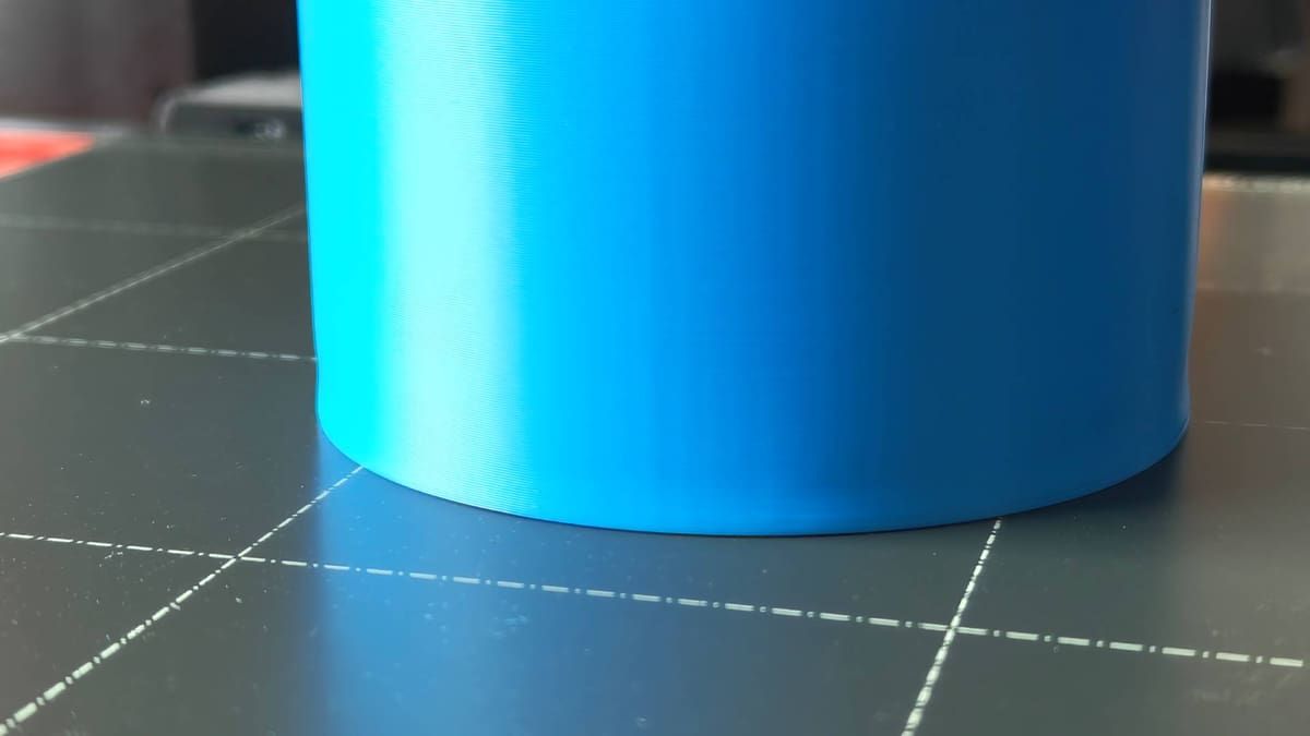
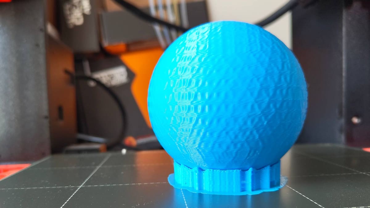
Uneven Outer Surface / Layer Uniformity
Perfect uniformity on the outer surface of a print is oh-so-satisfying. Unfortunately, there are a ton of things that can impact the looks of a print fresh off the bed. We’ll summarize common examples here, but keep in mind there’s a lot of overlap in 3D print errors.
Causes
Inconsistent cooling
A drafty printing environment can contribute to poor uniformity on the outer surface of a print.
Changes in print feature/speed
The printing temperature of molten filament remains constant during a print, but the features and speeds at which the printer is putting it down change. This means that prints with independent and isolated features adjoining larger areas will, in many cases, show subtle shifts in the transition from a long steady perimeter to a short, quick perimeter. This is best evidenced in the Benchy, which often shows a prominent line on the outside of the boat which corresponds with the beginning of the boat’s deck – consequently caused by the printer taking longer/shorter on a given layer and it cooling at a different rate.
Filament quality
Poor quality filament can vary in diameter throughout its many meters of length. On longer prints, this may appear visible with inconsistent layer lines on the outer surface of the print.
Likewise, filament left out in the open air for a long time can become “wet” or degrade in quality, resulting in poorer quality prints.
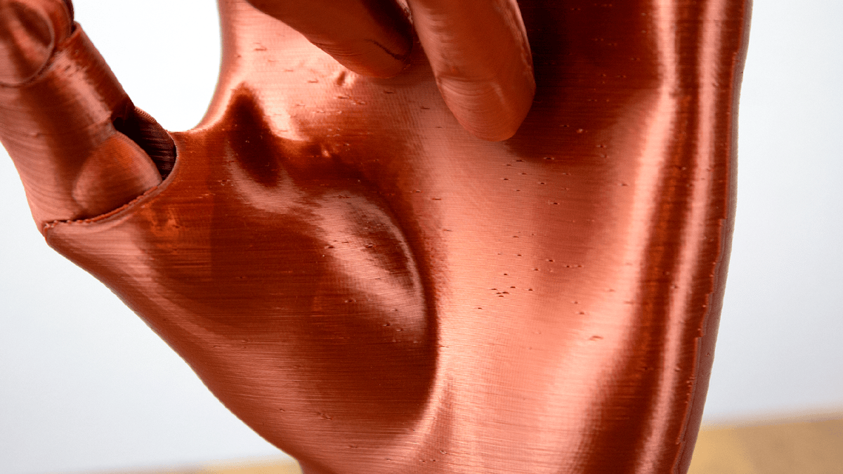
Filament Type
Some filaments – like the silky, glossy filament pictured above – show print imperfections more than others. In these situations, concentrating on dialling in your print settings and material profile is a likely worthwhile place to start.
Poor first layer
A poor first layer should, in theory, equalize out over the course of a print, but it’s better not to leave it to chance.
Suboptimal calibration/build
A perfect-looking print is a result of the tight quality in the build and calibration of the printer, plus software magic to compensate for where the hardware falls short. Errors in the hardware, such as binding bearings, loose belts, and untightened printheads, hot ends, and bed carriages, can all manifest as poor print quality, particularly the appearance of layer consistency on the outside of the print.
Additionally, subtle errors (or poor tolerances) in the build of the printer can compromise print quality from the get-go. Brought to wide attention by CNC Kitchen, the issue of an off-centered extrusion drive gear – entirely possible on inexpensive 3D printers where quality assurance can be iffy at best – can cause inconsistent transfer of force onto the filament, resulting in over- and under-extrusion in the print.
Coasting
The coasting option in your slicer is pretty innocuous, but it can have a knock-on effect for your print surface quality. Its function is supposed to stop the printer pushing the filament for the last few millimeters of an extrusion, to equalize the flow and reduce globs of stray filament at the subsequent travel move. When it’s not accurately used, though, the nozzle isn’t sufficiently primed for the next extrusion and it takes a hot second to reach the desired extrusion width.
Solutions
Preview your print and change the printing strategy accordingly
If your prints suffer from isolated layers of inconsistency on the surface, it’s probably a feature-based artefact. Oftentimes, you can see exactly how the surface quality of your print will look before you’ve even hit “print”. Depending on the slicer you use, you can preview the sliced model through a variety of filters that show the print and printer’s behavior in a new light. The default is usually the toolpath, with no visualization of flow or speed. This shows you the print as it ideally should be – perfect layers, no inconsistencies.
Changing the view to see the flow, speed, and cooling shows you the truth of your print. The logarithmic layer time, in particular, will help you understand where you may get inconsistencies on the outside of the print, caused by a sharp change in cooling rate from one layer to the next. Similarly, a view showing volumetric flow can help you spot inconsistencies in what would otherwise appear to be a smooth surface.
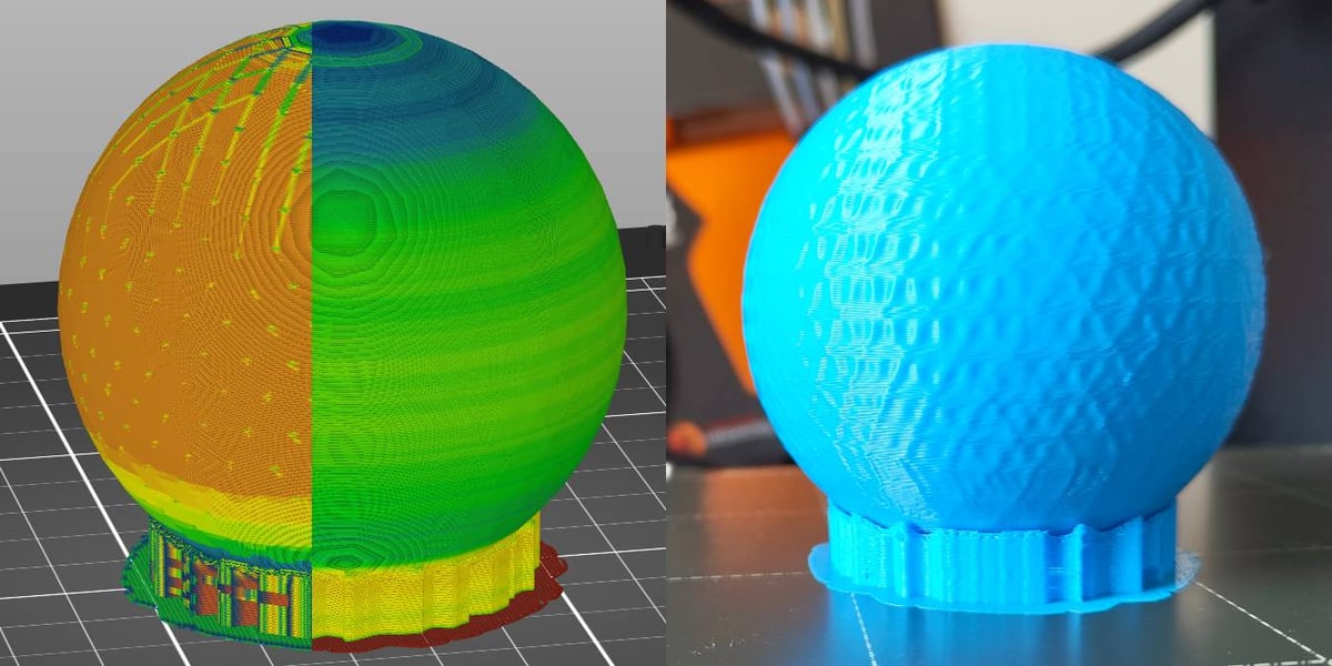
Getting in the habit of checking these views can help you adjust slice settings to mitigate them before you waste time and filament. The three crucial filters to see how the print will look are:
- Speed
- Volumetric flow
- Feature type
Eliminate temp. changes/drafts
If your printer is near frequently used windows or doors, or positioned somewhere that could catch a draught, move it, or consider enclosing it for environmental stability. Control of temperature is crucial for clean, successful prints, and uncontrolled cooling from a draft will subtly affect your print quality.
Eliminate vibration
As a 3D printer does its thing, it moves a lot. This is a given. At higher speeds, all that moving generates a lot of vibrations, and a printer that’s not particularly tight may transfer some of that “wibby-wobblyness” into the prints. This compounds when the surface the printer sits on isn’t stable either. You can dampen this with something sturdy and heavy, like a paving block, and insulate that from the surface with foam or similar vibration-absorbing material.
Ensure filament quality
This is a bit trickier to quantify. You’ll know if your filament is “bad” or “wet” when you hear popping sounds as it extrudes. Many filaments are hygroscopic, meaning they absorb moisture from the atmosphere, and this can impact print quality as the moisture evaporates under the heat from the hot end.
PLA filament, generally, can be left out with little consequence. If you’re convinced it’s bad, there are ways to dry it out. PETG, ABS, ASA, and others, particularly Nylons and flexibles, are more adversely affected by moisture and should ideally be kept in a protected environment between prints. If that’s not possible, dry the filament now and then to keep it in printable shape.
Check bed level/Z-offset
The “have you tried turning it off and on again?” of 3D print troubleshooting, fine-tuning the gap between your nozzle and bed leads to better first-layer adhesion and, consequently, less chance of warping on otherwise unchallenging prints.
Double-check to see that the nozzle gap for your first layer is the best it can be.
If your printer offers any form of “automatic bed-leveling,” you can skip this step.
Check your printer’s build
A troubleshooting tip more for those with printers built from kits or recently modified, fixed or upgraded hardware: giving your printer a once over to check that belts are tight (but not too tight), leadscrews and bearings sufficiently clean, greased, and square, not to mention the X-axis gantry correctly trammed to the print bed, idlers appropriately engaged, extruder idler tight (but not too tight), eccentric nuts correctly engaged (you shouldn’t be able to wobble the print bed carriage or printhead off their tracks), and hot end and nozzle securely seated.
A fully assembled printer from a reputable manufacturer is less likely to need this kind of quality assurance check, but it doesn’t hurt to know your printer better and check these things out anyway.
Turn off coasting
It may not fix inconsistent layers entirely, as many things can cause it, but turning off coasting can reduce the severity of inconsistent layer lines. This, of course, comes with the possible consequence of making your seams more pronounced, which is likely why you wanted coasting in the first place – it may be easier to find a better seam strategy and fiddle with your retraction settings, instead.
Recalibrate flow
Optimal flow settings for your prints will vary from filament to filament, and in the mix of switching, perhaps you’ve ended up with suboptimal values. It’s a long shot, and we’re confident most solutions for this problem are above, but if nothing else has worked, maybe this is it.
Check/Replace extruder drive gear
This tip, unearthed by the CNC Kitchen YouTube channel, suggests you investigate the filament drive gear in your extruder for either an off-center bore in the gear, or off-center seating of the gear – from the bore being too large for the extruder motor’s driveshaft. The consequence there is that when you lock it in place with a grub screw, it forces it to sit off-center and consequently results in inconsistend tension as the printer feeds the filament.
If either of these situations applies to your printer – more likely to be found on inexpensive printers using low-quality components – replace the extruder drive gears with a reputable alternative.
Vertical Patterns, Banding and Ghosting on Outer Walls
Regular patterns and lines on the outer surface of a print are ugly and undesirable. Thankfully, their predictability is a blessing, making them easy to diagnose and fix.
Causes
Infill showing through walls
If you see regular, uniform lines on the outside of your print, it’s likely that you are seeing the infill pattern. While the infill should connect to the walls for strength and stability, it should not be visible from the outside. There are a small handful of settings that can affect how much the infill overlaps with the walls, in addition to wall settings that do more to hide this overlap.
Debris and/or loose parts
A shaky (often quite literally) printer build, and/or bits of dirt and debris trapped in the various contact points of your printer’s motion system, can be a problem. It manifests in your prints via the inconsistent transferal of movement to the nozzle, leaving artifacts and possibly even lines in your print.
“Vertical fine artifacts”
The bane of many a print, the appearance of “VFAs” manifest as a tight, regular pattern that is fixed in the X- and Y- coordinates of a print. That is to say, they will appear perfectly vertical on flat, vertical planes, curve with curved surfaces, and propagate perpendicularly on diagonal planes. They appear to be linked to the cycling of the stepper motors controlling the X- and Y-axis movement plus the belts they drive, so short of upgrading to better stepper motors and belts, there’s not much you can do about it besides toying with the print speed to find your motors’ sweet spot. On the plus side, their absence means the problem is hidden by other issues in your print, so congrats on reaching a zone of diminishing returns in your troubleshooting! Silver linings, as they say.
Ripples around corners and features (direction changes)
Your printer’s print head movements are not 1:1 perfect translations of the electrical impulses that power them. It carries inertia into direction changes and wobbles back and forth as it settles into the new direction, manifesting as ripples in your prints.
Improper input shaping values
Some 3D printers are equipped with the firmware and hardware required to measure and compensate against ripples around the corners and features of a print. Improper values could result in the persistence of these wavy-looking lines on the surface of your prints, as your printer attempts to counter the wrong frequencies.
Solutions
Hide the infill
Your infill should stick to the walls of your print, but not so much that it imprints and is visible from outside. The quickest fix for this is to set an additional wall in your slicer settings, increasing the shell thickness of your print and creating more of a buffer to eliminate this unwanted effect.
Alternatively, if you’d prefer not to do that, tinker with the wall overlap settings, which determine how much your infill will overlap with your print’s inner wall. This setting is usually active by default at a low value. Lowering the value further will reduce the impact of this overlap, but be careful that it doesn’t result in the infill not sticking to the walls.
Check/Clean your printer’s motion system
Inspect all the contact points between belts and pulleys, leadscrew motion, and the print bed carriage’s travel path – all points where something moves over something else – for debris that could interfere with the printer’s motion. Use dry, lint-free cloths where possible to brush dirt and debris away. Do not use the same cloth for lubricated and unlubricated components.
Tip: Even if cleaning your printer doesn't fix the lines in your print, it's a good habit to get into for your printer's long-term performance and reliability.
Tune your print speed
If you’re sure that you’re dealing with VFAs, short of upgrading your stepper motors (which is more than a simple drop-in replacement – it also requires adjusting and recompiling your firmware), you can experiment with your print speed to find your particular motor’s print-speed sweet spot. There are numerous models out there for testing this – here’s ours: slice your model with a variable print speed, increasing by XX mm/s every 25 layers. Holding the complete print up to catch the light, it should be apparent which speeds show the VFAs the strongest.
Tip: Darker, glossier filaments will show the effects clearest. Avoid white filament for troubleshooting test prints.
Slower print speed
If you see ripples or “echoes” of movement around the corners and features of your print, slowing the wall print speed will lessen the effect. Take care to only change the wall speed, otherwise, you’d be slowing all parts of the print to no real benefit.

Tighten belts
Another step to mitigate ripples and echoes in your print surface is to ensure the appropriate tightness in your motion system.
If your 3D printer has belt tensioners built into the X- and Y- axes gantries, tightening the belts is a simple case of twisting the knob to tighten them. They should be tight enough to resist being pinched together. (Note this applies only to bedslingers with open belt paths.) To be exact about it, you can consult a guitar-tuning app to hone your belts to the appropriate frequency. This may be overkill, however, particularly if your printer can measure its frequencies and offset against them.
Re-run input shaping calibration
If your printer offers it, run your input shaping (vibration compensation) calibration routine again. This should mitigate most, if not all, ringing issues in your prints.
Tip: Input shaping becomes particularly useful at higher print speeds. A well maintained and tuned machine at lower speeds is less likely to need it.
"Zits" and "Blobs" on the Surface of the Print
These seemingly random flecks on the surface of a print can ruin the appearance of what would otherwise be a fine print.
Causes
Seam placement
Every part of a given layer begins and ends at a certain point. On the outer walls of a print, this start/end point boundary is known as the seam. It is an unavoidable part of 3D printing.
How noticeable it is can vary, though. You can choose how exactly the slicer handles this in the print settings, with one such outcome to place each point “randomly.” Random seam placement usually looks bad, and arbitrarily increases your print time with no real benefits. Alternatively, you can align the seam according to a number of characteristics of the print. Some filaments naturally hide the seam well, so it can be a combination of factors that result in a “bad” seam.
Improper print/material settings
Poor retraction for a given material with your printer can result in messy moves on the surface of your print, as too much or too little molten filament extrudes and either pushes out from the surface or leaves a pit. Reining in your retraction settings will reduce the severity of the layer change lumps and smooth the transition.
Coasting is a print setting in your slicer that can exacerbate a noticeable seam, too. Rather than backing off with filament as it approaches a layer change and coasting the built-up pressure in the hot end, improperly set coasting can under-extrude in and out of a layer change, which is even more noticeable as zits and blobs in a print.
[High printer dependency] Some printers are equipped to implement pressure advance, a firmware trick that logarithmically alters the feed of filament flowing through the nozzle as the print head accelerates and decelerates. This value can be manually calculated for a given material with test prints and corresponding calculations to find the needed values. Getting them wrong can result in flaring corners and pits or blobs on outer walls at layer changes.
Printer lag
Broadly speaking, a 3D printer is only ever following a set of instructions to achieve a print.
Models with curves or complicated geometry may pose a challenge to older 3D printers with 8-bit mainboards. With possibly hundreds of minute movement commands to process and execute while printing, you may end up with skips and lag in the printing – imperceptible pauses in the movement that give time for the printer’s processor to catch up – that leave tiny points of over-extrusion on the outer walls of a print.
Model errors
Not all seemingly solid 3D models are. Some hide impossible-to-print geometry that can result in undesirable printing errors. Many slicers will warn you of printability issues and can fix the model using their built-in tools, and this is usually enough.
If funky print aberrations continue to ruin your prints with no obvious solution, sometimes kicking the model into software like Meshmixer and using its “Inspector” tool can help you quickly identify and fix geometry errors.

Solutions
Seam Placement Settings
If your seam placement is currently set to random, change it to one of the “hidden” or fixed placements. It won’t eliminate the seam but pushes it into a corner or fixed vertical line through the model, making this inevitable aspect of 3D printing a little more aesthetically pleasing.
Adjust Retraction
Retraction can host a tricky bunch of settings to dial in, particularly when they can be responsible for a handful of different printing issues. If your extruder is a bit leaky (no judgment – we’re all friends here), it could benefit from increased retraction distance. Taking the settings you have now, add 0.5 mm to the retraction distance and print a quick test model to see the change. Repeat printing with 0.5 mm added each time, and monitor the change. You won’t eliminate the issue entirely, but you should see some small improvement.
Tip: If this doesn't help, revert to your original value and try something else. Arbitrarily leaving a value changed to no effect is a fast way to lose track of your changes and introduce new problems later.
Calibrate Pressure/Linear Advance
Combating over-extrusion at direction and layer changes using math, the pressure advance (or linear advance) firmware feature takes into account the pressure buildup in your hot end, and adjusts the feed of filament to compensate, alongside the accelerations and decelerations of your print head.
Many modern printers, including those from Creality, Bambu Lab, and Prusa Research, ship with either default values that do a good overall job, or automatic calibration routines that the printer can detect and use to adjust the values itself. If you know your printer to be one such case, skip this step. It’s likely not your issue.
For older printers with the appropriate firmware (basically, any Klipper and Marlin 1.5 and newer) that do not calculate their linear advance/pressure advance values independently, you must print some test models, measure them, and do some math. Our guides to linear advance/pressure advance for Klipper and Marlin cover this handily.
Increase Print Resolution Value
This tip is for folks with older printers hosting 8-bit mainboards. Increasing the print resolution value, which is to say, spacing out the points of a curve that your slicer instructs your printer to move to, will lighten the load on your printer when printing curved geometries.
Here’s where to find the print resolution field in three popular slicers:
- Cura: Go to “Mesh Fixes” > “Maximum Resolution”
- PrusaSlicer: Go to “Print Settings” (Advanced mode) > “Advanced” > “Slicing” > “Slice Resolution”
- Orca Slicer: Go to “Quality” (Advance mode) > “Precision” > “Resolution”
These fields may already have values – typically a small number. Increasing this value will increase the distance between points in the curves. At such tiny distances, the change will be imperceptible but result in much less work for your printer to parse while printing.
Check the model for errors
We chalk this tip up as a last port of call type solution, of the unlikely-but-not-impossible kind. There are a handful of model repair tools available to scrub out any non-manifold edges and a lack of watertightness in your model.
It can also be useful to load your model into a file viewer that renders the mesh in a style that makes the triangles easy to see. Doing this can reveal imperfections that aren’t wholly apparent in a slicer. Reducing unnecessarily high triangle counts can smooth out imperfections that might have manifested as blobby bits on the surface of your print.
Messy Overhangs
The rule of thumb for the cleanest overhangs was to stick to 45° or less, but modern printers seem to be pretty comfortable going higher and higher, so what do we know.
Needless to say, going for sheer overhangs comes with the risk of a messy finish on the print and even print failure, mainly due to improper cooling, slicing, or simply pushing your combination of machine and material beyond their limits.
Causes
Improper speed/cooling
Appropriate cooling is integral to a successful overhang, since part of the extrusion is unsupported. Not enough cooling, be it from printing too fast for the material to solidify quickly, or not pushing enough air, can result in your overhangs losing shape and looking messy.
Solutions
Adjust print speed & cooling
Ensure in your slicer that the respective overhang cooling settings are active. This mainly serves to slow down such parts of the print. Be wary of cranking the cooling too high, particularly when you also slow the print speed, as this can result in the overhanging part of your print curling and putting the print at risk from collisions.
Design for 3D printing
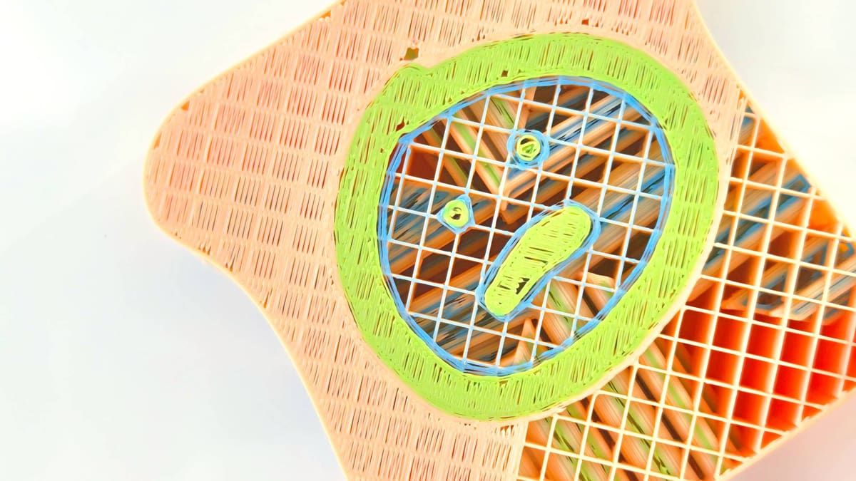
If you have a shelf-style overhang, an easy solution is to slope the wall at 45º so that the wall supports itself and the layers can reliably stack on top of one another. This applies to holes and pass-throughs for hardware on your prints, too – desktop filament 3D printers are not the best at achieving perfect circles perpendicular to the build plate, so better to just avoid them for shapes like hexagons or teardrops, which are self-supporting.
Orient the model differently
Are you certain the model needs to be printed as you currently have it? Sometimes the solution to poor overhangs is to change the model’s angle as oriented on the build plate. Rearranging your model and adding some supports could simplify the print, even if it looks counterintuitive on the build plate.
Add supports
While using support structures uses additional material and can worsen your print’s finish, they are a useful tool to help your 3D printer achieve otherwise impossible features like sheer overhangs. Your slicer has many settings to configure the support structures to your liking, but default values are often good enough for most scenarios.
Split the model into pieces
Another way to tackle insurmountable overhangs is to break the model apart into separate prints. With some models, this enables you to turn an overhang into a base. Of course, it introduces a new challenge in sticking the part back together again, but some slicers offer tools to help you do this, such as adding pin-style connectors.
Unsmooth/Stepping Curves
Unlike in CNC machining, curves in 3D printing are, mostly, not actual curves at all: they’re a sequence of straight lines. The result is usually good enough, but there are a few things that can cause them to look not so smooth.
Causes
Low-poly model
To keep file sizes low, some modeling apps and slicers generate primitive shapes at low resolution (highly detailed and poorly optimized files can be prohibitively large). Zoomed out in a slicer, such models’ curves may look smooth, but they aren’t.
Low-resolution slice
Slicing software typically defaults to make some compromises for efficiency in the G-code file it outputs. Taking into account the extrusion width and other characteristics of the print, it’d be inefficient to trace your model directly, so averages are made, and a maximum deviation value is allowed for the slicer to pick a path within an accepted tolerance. On curves, this “resolution” value can result in stepped-looking curves, keeping in mind that for many printers, curves are not curves when printed.
Streaming G-code
If you stream print files to your printer via USB cable (which’d be old hat in 2025, but we’ll roll with the notion) instead of copying them to the printer’s storage, it’s possible to run into the issue of the transfer rate not being fast enough, or the printer simply not being able to keep up with the pace of commands as they come in. This can result in skips and stalls, particularly on overly high-resolution “curves” (again, not really a curve).
Solutions
Increase curve resolution
Changing this one value can dramatically smoothen stepped-looking curves in your prints, by decreasing the accepted deviation from the model. While this fix will improve the visual quality of your print, it will also increase the file size and processing time for your computer and slicer, not to mention increase the possibility of skips and stalls on old, 8-bit 3D printing hardware.
Print from the printer’s storage
If you aren’t already, print your files directly from storage on the printer, be it inbuilt or removable flash storage like a microSD card or USB thumb drive. The point is to not be streaming the file from the computer.
Use a slicer with Arc Welder
Arc Welder is a recent addition to contemporary slicers, which takes a look at curved parts of your slice and converts the G-code from the typical linear-step processing to an actual G2 and G3-based curve. The main benefit of this is vastly reducing the instruction count and making files lighter. As far as a troubleshooting solution goes, this is only likely applicable in situations where you have a large object with large or many curves; all you’re doing is reducing the instruction load on your printing setup.
Surfaces Beneath Supports are Rough
Unless you possess the luxury of a muti-extruder or a similar multi-material 3D printer, your support material is the same as the print material. That can make support structures tricky. They need to form well enough to support the model without sticking too well to the print’s surface. Modern slicers handle this well, with diverse support types and decent default settings.
The material you use can also affect this, with PETG standing out as a material that sticks very well to itself.
Know that it’s inevitable that, where support structures are needed, the print quality will suffer slightly. By how much depends on the severity and shape of the overhangs that are to be supported.

Causes
Too much support material
Default support material percentages can skew a little high for some print jobs. This leaves you with more post-processing work to remove it all, particularly if your support offset isn’t quite dialed in and the support material sticks too much to the model.
Sub-optimal support offset
There are advanced support material settings in your slicer to determine exactly how support material interacts with your model. One setting is the offset, determining how much of a gap exists between the end of the support structures and the beginning of the model. Too fine a gap and the supports can stick to the print, making it difficult to remove them without leaving a mark, and too large a gap means the supports don’t actually support the extrusion.
Poorly tuned machine
Clean, easy-to-remove support structures rely on precision, and if your printer is not in tip-top shape, then deviances from improper flow, slop in the build and mechanics, plus the myriad of other things that can be wrong with a printer will impact the quality of your supports and the overhangs they are supporting.
Solutions
Fine-tune your support offset
If you find your supports can be removed easily, but the surface beneath the support is droopy and poorly defined, test lowering the offset value a small amount. This closes the gap and increases the stability of the support your support structures are giving to your print.
If you have the opposite problem and the supports stick too well to the model, test increasing the support offset by a small amount. This increases the gap and reduces the contact between the support structures and the model.
This setting goes by slightly different names, depending on the slicer you use:
- PrusaSlicer – Top/Bottom Contact Z Distance.
- Bambu Studio/OrcaSlicer – Top/Bottom Z Distance
- Cura – Support Z Distance
Reorient or redesign your model
Sometimes the simplest thing to do to improve overhang quality is to make them not overhangs. Reorienting your print or splitting it into multiple parts may provide an elegant solution to your overhang troubles.
Address other issues in your printer first
If your concern with overhang quality and the supports beneath them is one of many with the quality of your prints, then consider approaching this particular step holistically; deal with other fundamental flaws with your printing first. It could well be the case that the issue here disappears when you’ve tightened up in other areas of your printing game.
Fine Detail Not Printing Correctly
Small features do not print cleanly or simply fail to print at all. This is most prominent when you’re trying to print tall, features.
Causes
Printing beyond your nozzle’s abilities
If the feature you are trying to print is smaller than the extrusion width – which is typically determined by the size of the nozzle you are using – then your slicer may simply ignore it.
Improper cooling behavior
Fine detail, such as a spike protruding up from a model, can suffer from the accumulation of heat when the printhead chugs away, layer by layer, without retreating every now and then to let the material cool. Ordinarily, a forced pause like this isn’t necessary since printing the rest of the model achieves the same thing, but if the only thing left is a fine, isolated part of the model in a small area, the heat can build up and deform the model.

Solutions
Switch to a smaller nozzle
Logically, the smaller the bore nozzle you use, the smaller the details you can print. Virtually all desktop 3D printers come with 0.4 mm nozzles as standard, so consider switching to a smaller compatible nozzle.
A consequence of this is that your print time will balloon since it takes more passes to put the same amount of material down. The decrease in extrusion width, however, lets the slicer path finer detail that larger nozzles aren’t capable of achieving.
Set a minimum layer time
The longer the nozzle spends in a small area of the print laying down fine features, the more heat builds up and challenges the printer’s ability to cool the plastic enough. Slicers typically offer a “slow down” or “minimum layer time” setting to mitigate this. The logic for each may differ, but the effects are similar.
This setting goes by slightly different names, depending on the slicer you use. They are all found under the “cooling” areas of the slicer settings:
- PrusaSlicer – Slow down if layer print time is below
- Bambu Studio/OrcaSlicer – Slow printing down for better layer cooling
- Cura – Minimum layer time
Note: There are complimentary settings to adjust for some of the above – it may require experimentation with other settings like minimum speeds and fan speeds to find the sweet spot.
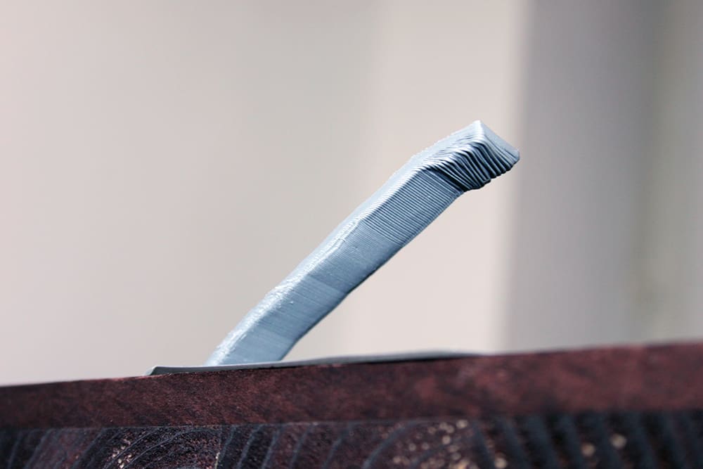
Diagonal Scars on Print
These unsightly lines appear on the top layers of your print, like a scar running across the grain of the layer. Fortunately, they’re easily dealt with.
Causes
Nozzle travels across the surface of the print
The pathing your slicer creates for your printer usually prioritizes efficiency. Travel paths take the shortest route to the location for the next instruction, things like that. This means it’s possible to end up with a print that has your printhead travel “through” a layer to either its end position (if the print is complete) or the location of the next extrusion. Without a Z-hop, the nozzle rubs up on the surface of the print and leaves a scar-like track in its wake.
Nozzle oozes excess filament across the surface of the print
As with the cause above, the pathing your slicer has calculate is ultimately responsible for this printing issue. And if it’s not the nozzle scraping a scar into the print, then it’s excess filament oozing onto the top layer, instead.
Solutions
Enable Z-hop
If your filament retraction settings are decent, then a simple fix for scars on the top surface of your prints is to ensure that Z-hop is enabled. This setting instructs the printer to raise the nozzle above the print when it is moving to a new position. In a single stroke, this eliminates print scarring from nozzle drag, but it may not address marks left by a leaky hot end oozing too much filament.
Set travel moves to avoid the print
Coming at the cost of a longer print time, setting your printer to avoid printed parts when executing a layer change or travel move will alter the pathing your slicer creates, and force the printhead to take a longer route to avoid crossing over the printed part.
Print Looks Melted and Deformed
A print can sometimes succeed but still look wrong. Overly glossy and bulging – there’s a loss of sharp detail. This is, more often than not, down to too much heat.
Causes
Incorrect filament profile
Using the wrong filament profile for a print is easier than you’d think. Mistakenly using an ABS profile for PLA material will quickly result in a globby, low-quality print.
Hardware malfunction
3D printing requires exacting temperature control to melt, and then quickly cool the plastic into the desired shape. Components can fail, including the thermistors that relay temperature to your 3D printer’s brains. A faulty thermistor could manifest in suspicious behavior around temperature, such as needing to print higher temperatures than your material requires to get anything resembling decent performance.
Solutions
Increase minimum layer time
If you’re finding your print looks bad only in smaller, isolated areas, it could be the case that there’s a build-up of heat from the hot end lingering on the same part of the print. You can mitigate this by increasing the minimum layer time, forcing the printer to slow down on what would otherwise be a quick layer, giving the plastic more time to set, and better preserving the part’s shape and definition.
If a layer, even at lower print speeds, completes faster than the minimum layer time, the printer will park and wait before starting the next.
Double-check your temperatures
Check that your temperatures are in order. Ensure that the filament profile in your slicer is appropriate for the material you are using.
Check the hardware/firmware
If your print and material settings look good and the issues persist, check that your printer controls the heat and relays it reliably and as expected. Pay close attention to your printer’s display and temperature reading as it heats, noting whether it overshoots the target temperature and struggles to hold steady, inconsistently dips below and shoots over target, or, in extreme cases, runs hotter and hotter, eventually damaging the printer. These are signs of the firmware values governing your printer’s thermistor being off or, more likely, damage to the thermistor itself. It is a delicate component, and can easily become damaged after basic print head maintenance or following a large blob build-up on the hot end.
This is a deeper topic than we can cover in this section, but here are our guides to the topic, which will orient you on thermistors and what you can do to resolve issues with them.
Pits and Hollows in Top Layer (Pillowing)
The top layers of a print, particularly models with large, flat planes as their top surface, have the printer extrude lines of molten plastic into thin air between infill contact points. Insufficient infill support, or cooling issues can overstretch the plastic’s ability to lay neatly, resulting in a messy appearance. Fortunately, this is an easy issue to address.
Causes
Not enough infill/suboptimal infill pattern
Depending on the infill pattern used and how much of it you have, your print can end up with large voids that the top layers bridge across. It’s inevitable that the initial top layers of a print, spanning large gaps like this, will droop into the hole.
Not enough top layers
Some drooping into sparse infill is inevitable, and only having one or two top layers will leave this highly visible on your prints.
Solutions
Change infill pattern
Some infill patterns leave large voids at low percentages. Experiment with the patterns available in your slicer – you may find one that lets you keep the percentage low but provides sufficient support for your top layers as they are.
Increase infill percentage
The quickest fix to pillowing is to increase your infill percentage. This comes at the cost of greater material usage and print time, though, so consider whether your time is better spent finding other optimizations.
Increase the number of top layers
Pillowing happens, but you can mask it effectively by increasing the number of top layers you print. Over a few layers, the pillowing effect equalizes and, eventually, you can’t even tell there was a problem. The trouble with pursuing this fix is that you can’t be sure how many additional top layers will be enough to eliminate the issue. We suggest you try a mixture of infill adjustments and top layer changes to minimize the pillowing, rather than hiding it with more top layers.
Web-like Strings Cover the Print (Stringing)
A bit of stringing isn’t an issue, but excessive stringing that requires thorough post-processing can indicate problems with your print settings, or filament.
Causes
“Wet” filament
If, during printing, you hear faint popping and crackling sounds from your extruder, then your filament is “wet” – it has absorbed moisture from the atmosphere, and now that moisture is interfering with your print.
Dirty nozzle
Blobs and charred filament remains on the outside of your nozzle can interfere with extrusion and leave string-like-whisps of filament on the outside of your print.
Filament type
Some filaments string a lot. Flexibles, in particular, are notorious for stringing. Optimization can help, but often it can’t be entirely eliminated.
Solutions
Switch/dry your filament
If you’ve identified that your filament is wet, or you are using a flexible like TPU, then drying is possibly the single most effective thing you can do to help the situation.
There are many ways to dry your filament (and then to keep it dry). Consult our guide to drying filament for some top tips.
Clean your nozzle
Heat your nozzle to a temperature appropriate for the material you are currently printing. Once at temperature, use a brass wire brush to gently scrub the nozzle tip, removing any filament buildup and charred debris as you go.
Once the nozzle looks clean, extrude a short amount of filament through the nozzle to ensure the opening is clear and debris-free – the plastic may wiggle and curl initially before settling into a smooth, straight extrusion falling from the nozzle. Once your extrude command has finished, brush this fresh filament aside, and you’re good to continue printing. That, or set your printer to cool down. Do not leave it at temperature unless you plan to print something immediately.
Live with it
This isn’t the most elegant of solutions but simply taking a scalpel or a heat gun to the strings is often the quickest and easiest solution. If the print beneath the strings is still complete, strong, and looks good with the strings nicked away, is it even a problem?
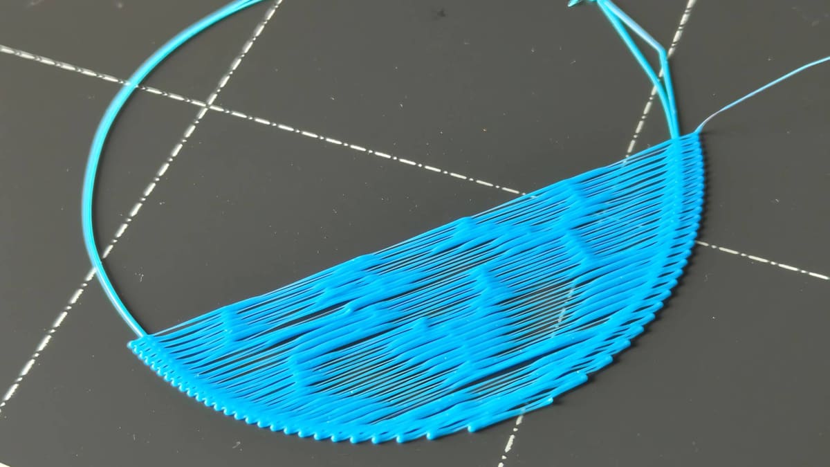
Bridges are Messy/Droopy
Most filaments are surprisingly resilient to bridging. With a finely tuned printer, you can achieve surprisingly long bridges. However, something isn’t quite right when your printer fails to bridge even the smallest gap.
Causes
Material not cooling quickly enough
Bridges are unsupported expanses of extrusion. For them to print successfully, the plastic must harden (cool) enough to support itself. Otherwise, it can sag and droop into the space beneath. This can be due to many things, including the temperatures you are printing at, the efficacy of your printer’s cooling, and the print speed at which the bridged section of the print is printing.
Solutions
Check that your bridging settings are appropriate
Modern slicers, such as Cura, PrusaSlicer, Orca Slicer, and Bambu Studio, all incorporate bridging-specific settings that tip the balance towards successful bridging in your prints. The defaults are usually good enough for general purposes; check that they’re at their default values and that those don’t work for your bridging before changing anything else.
These settings typically include a bridging fan speed, found within the material-specific cooling settings, and bridging speed, found within the general print speed settings.
Bridging print speed is always slower than other aspects of a print layer. Cooling, depending on the material, will vary. For PLA, the default is 100% cooling on bridging, while PETG may be 50% cooling.
Any bridge print setting that doesn’t align with what is described above may be suspect – reset to the material and profile defaults to see if that improves things.

Slower bridging print speed
Lowering your bridge printing speed by small increments when printing a bridging test print should help you quickly identify the ideal bridging print speed for your setup.
Use supports
Consider if your print even needs to be bridging “au natural.” Tactical usage of support structures can handily deal with pesky overhangs and leave you with a clean print. Organic, or “tree” supports minimize the amount of material used, so the tradeoff of print quality to wasted filament may not be so bad.
Whispy-looking gaps in the print (Under extrusion)
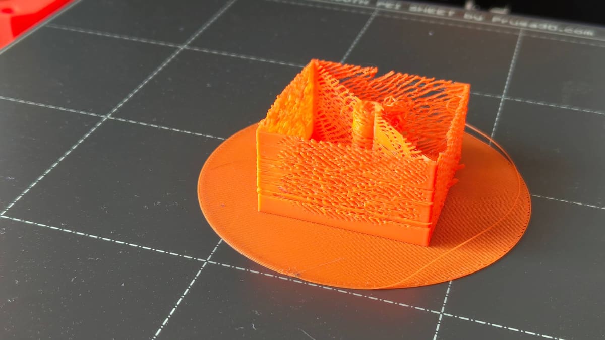
Characterized by whispy, uniform patterns of extrusion, under extrusion is typically a result of a blockage somewhere in the filament path, with easy-to-fix causes including tangled filament, dirty extruder gears, and advanced issues such as heat creep in the hot end.
Causes
Partially clogged nozzle
Even something as innocuous as switching between low and high-temperature materials can result in a blockage, as remnant material is subject to a temperature it is not designed for. Low temperature materials like PLA can burn up, leaving charred debris, and higher temp materials simply don’t flow and interfere with smooth flow at lower temperatures.
Likewise, using fiber-filled materials such as PLA-CF, can result in a buildup of particles and debris.
Heat creep
Not all hot ends are designed equally, and some simply don’t do well with too much heat. The characteristics of some filaments mean that certain printing conditions, such as printing PLA in an enclosed 3D printer with insufficient cooling, can result in softer filament plugging the filament path above the point where it should melt. This is, in simple terms, what heat creep is, and it can be a pain to unblock.
Dirty extruder feed gears
Set too tight, your extruder idler tension can cause the drive gears to chew the surface of the filament, generating plastic dust that can clog up the toothed profile of the gear, reducing its ability to smoothly grip and feed the material.
Solutions
Inspect the filament path for debris and blockages (including nozzle)
Check the whole filament path, from spool to nozzle, inspecting for tangles, debris in the filament guide tube(s), the condition of the extruder drive gears, and eventually, the nozzle’s ability to smoothly extrude filament.
Rectify as you go, but if you make it to the nozzle with no obvious cause for the under-extrusion, then it’s likely the issue is inside your hot end.
Heat the nozzle to a temperature appropriate for the loaded material, and run an extrude command. Observe the nozzle for filament extruding smoothly without interruption or lateral movement that would suggest a partial blockage.
At this point, you have two options for clearing the blockage:
Unblock the nozzle – needle method
The standard nozzle opening on a desktop 3D printer is 0.4 mm – just large enough for you to stick an acupuncture needle into the opening and jam it around to dislodge whatever is blocking the filament’s way. Most 3D printers come with one as a freebie, but consider buying some or befriending an acupuncturist to “lose” some for you from time to time.
Steps: Unblock the Nozzle with a Needle
- Move the print head to an easy-to-access location with plenty of clearance beneath the nozzle
- Set the nozzle to heat to an appropriate temperature for your material.
- Navigate to your printer’s extrude menu option.
- When it is up to temperature, insert the needle into the hot end and gently run it back and forth a few times. Warning: the needle will also quickly heat up.
- Tap the extrude menu option on your printer. If the blockage is clear, the filament should start extruding again.
Unblock the nozzle – Atomic Pull
A stubborn blockage calls for tough action. The Atomic (or “Cold”) pull is one such tough-sounding action. To do it, you allow some material to partially cool in the hot end and then yank it back out through the cold side of the extruder.
Note that this method isn’t so effective for a fully blocked nozzle. The filament needs to be able to enter deep into the hot end, so a blockage further up the filament path will render it ineffective.
Steps: Unblock the Nozzle with an Atomic Pull
-
- High printer dependency: Eject the filament from your printer, remove the guide tubing, and prepare the print head so that you can feed the filament into the hot end by hand.
- Cut a 30 cm length of filament and keep it close. Heat the hot end to a temperature appropriate to the material you are using.
- Once at temperature, insert the filament into the hot end until it extrudes past the partial block. As soon as the filament extrudes, set the hot end to cool down to half of the printing temp you previously set (rule of thumb: you may find a different “cool” temperature works better). Keep the pressure on the filament in the hot end as it cools.
- Allow the printer to cool to the set temperature. The filament should have stopped extruding by now – if not, step down in 10 °C increments until it stops.
- Once you’re sure the material inside the hot end is no longer molten and flowing, grip the remaining filament on the cool side of the hot end and give it a firm pull until the filament pulls cleanly away. You will know the process has worked when the end of the material you just yanked shows an imprint of the inside of the hot end – typically a barrel-shape with a larger diameter than the filament and a conical end – and there’s evidence of burnt filament and other debris embedded in it.
- Repeat the process until the yanked filament comes out clean every time.
Increase print temp
If your printer’s preset temperatures for loading and unloading the material show no sign of under-extrusion or blockage, the solution may lie in your printing temperatures. Consult a material temperature calibration model to determine the optimal temperature for your material.
Tip: Consider keeping a log book of your optimal settings for your materials. It's easy to lose track if you're not diligently updating and forking your printer and material profiles as you tinker.
My Print Failed
Print Has Lost Dimensional Accuracy
There are many links in the chain that is “3D printing” where dimensional accuracy can drift. From basic oversights in the 3D model to a poorly maintained motion system, and even the inherent tolerance, the +/- variance, you can expect from your system. All contribute to a printed model being minutely, physically different from your desired results.
Causes
Sub-optimal printer condition
If your printer is incapable of accurately traveling the exact distances it is instructed to, nor extruding the required amount of filament, the print will not be dimensionally accurate. Paying attention to whether your print skews in a particular direction can help you narrow down where to look for the cause.
Mismatched units
Given the difference between metric and imperial units, this problem is easy to spot. For example, a model designed in inches, but configured and sliced using metric, will result in a much smaller print than expected. The reverse is true, too.
Design/slicing issue
The typical file types we use in 3D printing are, effectively, masses and masses of triangles, stitched together into a continuous solid. Models can be optimized to save space and processing time by reducing the number of triangles. In doing so, the model can stray from the dimensions as designed. This is particularly true of organic shapes and curves.
When your slicer is calculating the optimal path for the printhead to travel, depending on the print resolution values it’s adhering to, it too can average out intricate movements that fall within a set tolerance, further stepping away from the exact dimensions of the model as designed.
Recalibrate expectations
Desktop 3D printers have come a long way in the last few years, but they are not capable of the kinds of accuracy and tolerances offered manufacturing methods like injection molding. If you’re bothered about mere microns of inaccuracy in your prints, you may have set the bar too high for the prints your machine can produce, even in perfect conditions.
Solutions
Print test models and better understand your machine’s capabilities
Simple calibration cubes of a known width, height, and depth should be the first thing you check. Most slicers offer the option to create primitive shapes, and a cube is a simple, easy-to-measure print to get started. Print the cube out, and with a decent pair of calipers, check the dimensions as printed against the model’s dimensions and note them down.
For reference, we can consider the following values for most desktop FDM machines:
- Greater than +/- 0.5 mm is bad
- +/- 0.5-0.2 mm is average
- +/- 0.2-0.1 mm is good
- Less than +/- 0.1 mm is fantastic
Understanding where your machine sits on this scale gives you an idea of how to approach issues with your dimensional accuracy. At the “bad” end of the scale, your troubles are more likely to be mechanical, and with the condition of your 3D printer. On the opposite end, “fantastic,” your prints are fine, and to expect much better of the printer is unrealistic.
Use a smaller nozzle
Fine details, particularly text, are best printed using small-bore nozzles. Plain and simple. If you’re using the stock nozzle that came with your 3D printer (likely a 0.4 mm) and small, intricate elements of the print are messy or are simply skipped by the printer, then jumping to a smaller bore nozzle could well increase the physical resolution your printer is capable of.
Clean and maintain your machine
To rein in a wide tolerance in your prints, check the condition of your machine. Consult your manufacturer’s recommendations for maintaining your machine. Where none are given, this should run to include: lubricating the necessary components (linear rails, leadscrews, or ball screws), tightening belts to the appropriate tautness, and cleaning the motion paths of any debris, dust, and grime. Check for wobbliness, or “slop” in the build of self-assembled machines – print bed carriages and print heads that can be tilted by hand need to be tightened, usually at the eccentric nuts that help secure them to their respective axis.
Redesign the model for printability
Some features simply do not print well. Holes and round pass-throughs for machine screws when printed perpendicular to the print bed, distort from the overhang. Accommodate this by using fully self-supporting shapes that a printer can print well, such as hexagons or teardrops; you can achieve the appropriate clearance without messiness.
Likewise, with your printer’s tolerance in mind, you can adjust nesting or seated parts to slot together better. If you’ve familiarized yourself with your printer’s typical performance for dimensional accuracy, you can start to design features to print specifically well on your machine, such as different fit types between parts (clearance, interference, and transition fits).
Reduce speed / find optimal speed
Pushing a system faster than it can reasonably handle could result in misshapen prints. The simple solution is to slow things down. Many modern 3D printers tout high speeds, 500 mm/s and higher, but these numbers are rarely attained and only apply to specific materials and model characteristics. If you find yourself manually cranking the speed without referencing calibration models as you go, simply slowing things down could rein in your misshapen prints.
Calibrate extrusion
With your motion system checked and in tip-top shape, and some degree of certainty that the model and slicing resolution are not pulling your prints out of shape, then one final consideration should be whether your extruder is pushing the correct amount of filament for the speed and path your printhead is tracing.
Rather than delve into the depths of this calculation-heavy process, direct your attention to our dedicated guide to calibrate e-steps.
Cracks Appear in the Print (Delamination)
Similar to when a print warps free from the bed, the cooling and contraction of material can cause cracks to appear in objects. Some materials are more likely to do this than others – such as ABS and ASA.
Causes
Temperature Changes From the Environment
Exposure to changes in temperature from the environment, such as drafts, can cause uneven cooling of the print, contracting some parts away from others and splitting the model at some layers in the process.
Improper cooling settings
Easily overlooked, particularly if you’ve set up a custom material profile for a print, the use of print cooling fans on a material that needs high temperatures and little cooling will cause warping, possibly even cracks.
Printing too fast
Printing warp-happy high-temp materials quickly is a recipe for trouble on an open-frame 3D printer. With nothing to slow the print’s cooling, you risk a high degree of stress throughout.
Solutions
Enclose / Relocate your printer
Some printers are enclosed by design. If yours is, move along to the next tip.
Maintaining a stable environmental temperature that gradually cools will help prevent tricky prints from warping and cracking. You can cobble one together from cardboard in a pinch, but there are many alternatives for budget 3D printing.
Alternatively, if your printer is in a frequently used room with windows and doors opened and closed, consider moving the printer to a different room with undisturbed airflow and a stable temperature.
Use appropriate cooling
Not all materials need cooling as they print. Check the recommended settings of the filament you are using, and ensure that this is accurately mirrored in your print settings in your slicer.
If you can’t find specific settings recommendations for your filament, knowing the material type is enough for a ballpark idea. PLA requires cooling. PETG, less so, while the likes of ABS, ASA, PA, and PC are all materials that can be printed with their cooling close to disabled. Mind, this means only the global setting – there are some situations where cooling helps, such as bridging.
Layer Shift
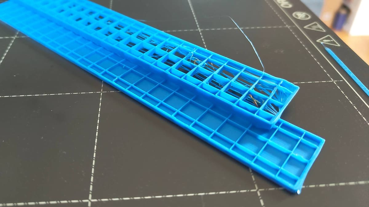
Your print leans where it shouldn’t. Typically this will only be in the X- or Y- direction of travel (or diagonally, in the case of CoreXY machines) and stems from interrupted motion. You have something called “layer shift”.
Causes
Overtightened or Loose belts
A loose belt can skip off the gear driving it, resulting in inaccurate movement of your printhead.
Loose drive gear
A drive gear not fully secured to the stepper motor’s D-shaped drive shaft can also result in the inaccurate transferral of movement to the printhead.
Debris and obstructions in the motion system
Foreign objects getting caught in the printer’s movements can also result in inaccurate, shifted prints.
Solutions
Check the Belts
The first port of call for diagnosing layer shifts is at your printer’s belts. You can narrow down which one to check by looking at the direction your print is leaning or has shifted, normal to its position as printed on the print bed.
Ensure the belts form a complete loop, passing neatly over idlers and the transmission gear that drives them. They should be taut enough to firmly resist being pinched together, but not so taut that they can’t be brought together.
Check the Drive Gear
The gear attached to the stepper motor driveshaft transfers motion to the belts. These gears are fixed to the driveshaft using a grub screw, and if it’s too loose, the shaft can slip and skip within the gear, resulting in imperfect movement on this respective belt. Check that the grub screw is secure and hand-tight.
Check for obstructions
Look around the belts, pulleys, and full range of motion of your printer for obstructions and debris that could be preventing the printhead from moving properly. This could be in the form of stray scraps of filament tangling in the belts, or something larger and less immediately apparent, like incorrect cable routing.
The "Blob of Death" / Filament Build Up Around the Hot End
The unmistakable “Blob of Death” looks catastrophic, but can often be salvaged with a bit of patience. It is typically caused by a print coming loose from the build plate, or an improperly assembled hot end leaving cracks and gaps for molten filament to leak.
Causes
Print didn’t stick to the bed
An improper gap between the nozzle and print bed can leave filament trailing from the nozzle and failing to stick to the bed. As the print proceeds, this can build up and eventually swallow the nozzle or, worse, the whole hot end assembly.
Improperly installed nozzle
If you’ve recently switched nozzles or other hot end components and forgotten to install (tighten) them securely, there may be gaps for molten filament to seep out and gunk around your hot end assembly.
Solutions
Make a decision
The blob of death is a nasty issue to deal with, particularly since the damage it can cause may not be obvious. In trying to fix it, you risk damaging the delicate cables of your printer’s hot end. For all the headaches it may cause you later, think twice about whether you have a realistic chance of removing it cleanly and safely.
If the design of your print head has many nooks and crannies for the blob to have seeped into, where heat from the hot end can’t reach, it may not be worth the effort to recover versus simply replacing the print head.
Remove the blob
If removing the blob is imperative, there are many steps and considerations.
- Raise your printhead/lower your print bed to give plenty of access to the hot end, and clearance beneath.
- Clear your print bed and cover it with some protective material, such as a sheet of cardboard.
- Heat your hot end to the lower end of the blobbed filament’s recommended printing temperature range. Let it sit, at temperature, for a few minutes to allow the blob to soak in the heat.
- Taking a pair of needle-nose pliers, pinch the blob and gently pull it down away from the nozzle. It may not come cleanly, or even in one piece. Take extra care where the blob encases the hot end wiring – these are delicate components and can easily be damaged.
- Slowly and methodically peel and pull as much of the blob as you can away from the hot end and surrounding assembly, until it’s as clean as you can get it.
- Once satisfied with the cleaning job, attempt to extrude some filament and observe how cleanly it does so. In the act of blobbing, your nozzle may become blocked. Best to check now before diving into a print.
- Pay particular attention to your printer’s ability to hold temperature. A crucial component in your printer’s ability to hit and hold temperature is the thermistor, which is typically very delicate and commonly a casualty in situations with the Blob of Death.
Note: Take care where the blob surrounds exposed hot end cables, particularly the thermistor. These are delicate and easily damaged. It may not be worth attempting to salvage the hot end if the cables are badly encased in a blob.
Something Else
Little/Nothing is Extruding
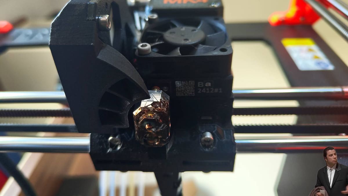
The printer makes the moves, but barely any filament is coming out – maybe even no filament. There are many reasons this could happen. Hot end and nozzle issues will typically be signaled by the extruder stepper motor skipping. Alternatively, it could be trouble with the material.
Causes
Ran out of filament
Forgive how on-the-nose this one is, but hey – it is a possible cause for extrusion issues. With no filament to feed into the extruder, the extrusion stops.
Snapped filament
Brittle fiber-filled materials and “wet” filaments can be prone to snapping. A break somewhere along your filament path means your extruder can no longer pull (or push) filament into the hot end.
Stripped filament
Stripped filament is where the feed gear of your extruder has chewed away at the filament and left it too thin to be reliably gripped and fed to the hot end. This typically results from other issues with your printer, such as a blocked nozzle or filament tangle.
Tangled filament
A knot around the filament spool will bring your printing to a sudden halt. This can happen after a spool takes a tumble and some loops spring free. Careful re-spooling is necessary to avoid introducing a tangle that won’t be apparent until later in your print. Improper storage can also cause this. The open end of the filament should never be left hanging loose on an unused spool.
Tip: Use the holes and grooves on the outer edges of a filament spool to secure the end. Alternatively, print a filament clip to do the job for you.
Blocked nozzle
The build-up of charred filament or other debris can block the opening of your nozzle. This problem can vary from a trivial fix to requiring invasive maintenance on your machine.
If your printer has been running fine, but suddenly experiences blockage-like issues when printing, it could be heat creep. In addition to clearing the blockage, you should consider altering your printing environment and possibly even the print settings to prevent it from happening again.
Improper bed level/offset
Calibrating the offset between the nozzle and print bed too tightly, be it via your printer’s controls and firmware, or by physically “leveling” the bed, leaves no room for the filament to escape. Depending on the print bed material, you may see gouging of the bed surface if this is the issue.
Tip: You will know you have a blockage when you hear the extruder motor clicking loudly.
Filament mismatch
Using a material with a much higher recommended printing temperature than the print settings you used will also result in no extrusion printing. You may see wisps of underextrusion, but if your temp falls far short of what’s needed, not enough plastic is melting to successfully flow out of the nozzle.
Solutions
Check the filament path
Inspect filament from the spool, through the guide tubing, and into the print head. Check for tangles at the spool, breakages in the guide tubing, and a clean entry into the hot end at the print head. Filament should be able to roll off the spool cleanly, with no breakages or interruptions to the filament path.
Re-level your bed
While the term is used broadly, the intention is the same, no matter the method used. This possible solution requires you to adjust the distance between your nozzle and print bed.
In manually calibrated printers, this means zeroing the Z-axis then disabling the stepper motors and making manual adjustments with each of the bed’s leveling screws. A sheet of paper is the usual tool of convenience for setting the appropriate distance. The direction typically given is to have enough friction between the nozzle and bed to trap the sheet, but not so much that the paper can no longer move freely.
Not all sheets of paper are created equal, so note that the paper leveling method does not necessarily give perfect results.
Run every point of the bed in sequence multiple times. A single pass doing the paper test on each point of a print bed with four spring-tensioned bed screws will not give a great level, as each subsequent point’s calibration will subtly affect the others.
Tip: Consider using a feeler gauge for setting a reliably repeatable nozzle gap distance
If your printer allows firmware-based Z-offsets (often found as the “Z-offset” setting or “Z-baby step” setting), adjusting it higher or lower will fix the bed’s position (or print head’s position) relatively. Entering this option through your printer’s menu will often position the print head for you, as with a manual printer, slide a sheet of paper between the nozzle and bed. Then, nudge the nozzle closer to the bed using the increments given by your printer until the sheet of paper catches, but is not pinned between the nozzle and the bed.
Note that the printer feature mesh-bed leveling does not typically set the initial nozzle-bed gap for you. It creates a map of discrepancies in the print bed and values for the printer to accommodate them in your first layers.
Unblock the nozzle – needle method
If you’ve checked every other possibility and are sure your issue is a blocked nozzle, you have a couple of options.
The standard nozzle opening on a desktop 3D printer is 0.4 mm – just large enough for you to stick an acupuncture needle into the opening and jam it around to dislodge whatever is blocking the filament’s way. Most 3D printers come with one as a freebie, but consider buying some or bribing an acupuncturist for some.
Steps: Unblock the Nozzle with a Needle
- Move the print head to an easy-to-access location with plenty of clearance beneath the nozzle
- Set the nozzle to heat to an appropriate temperature for your material.
- Navigate to your printer’s extrude menu option.
- When it is up to temperature, insert the needle into the hot end and gently run it back and forth a few times. Warning: the needle will also quickly heat up.
- Tap the extrude menu option on your printer. If the blockage is clear, the filament should start extruding again.
Unblock the nozzle – Atomic Pull
A stubborn blockage calls for tough action. The Atomic (or “Cold”) pull is one such tough-sounding action. To do it, you allow some material to partially cool in the hot end and then yank it back out through the cold side of the extruder.
Note that this method isn’t so effective for a fully blocked nozzle. The filament needs to be able to enter deep into the hot end, so a blockage further up the filament path will render it ineffective.
Steps: Unblock the Nozzle with an Atomic Pull
-
- Eject the filament from your printer, remove the guide tubing if present, and prepare the print head so that you can feed the filament into the hot end by hand.
- Cut a 30 cm length of filament and keep it close. Heat the hot end to a temperature appropriate to the material you are using.
- Once at temperature, insert the filament into the hot end until it extrudes past the partial block. As soon as the filament extrudes, set the hot end to cool down to half of the printing temperature you previously set (rule of thumb: you may find a different, cooler temperature works better). Keep the pressure on the filament in the hot end as it cools.
- Allow the printer to cool to the set temperature. The filament should stop extruding – if not, step down in 10 °C increments until it does.
- Once you’re sure the material inside the hot end is no longer molten and flowing, grip the remaining filament on the cool side of the hot end and give it a firm pull until the filament pulls cleanly away. You will know the process has worked when the end of the material you just yanked shows an imprint of the inside of the hot end – typically a barrel shape with a slightly larger diameter than the filament and a conical end – and there’s evidence of burnt filament and other debris embedded in it.
- Repeat the process until the yanked filament comes out clean every time.
Printer Tries to Move Beyond Its Limits
Before every print, a 3D printer must go to “home”. Also referred to as the “origin” or “zero” position, it is typically each extreme of each axis that the print head (and bed) can travel. Sometimes, a printer can be obstructed from reaching this zero point or attempt to move beyond it, making an alarming noise as it goes.
Tip: While it can be loud and panic you into a rush for the power switch, a stepper motor loudly skipping steps like this is unlikely to be damaged by it.
Causes
Obstruction in The Travel Path
Depending on your printer’s design, guide tubing or cables may block the path of the print head or bed.
Faulty/Disconnected Endstops
To print in the desired space, a printer needs to travel to its origin before every print. Many printers use endstops – some kind of switch, be it mechanical, optical, inductive, or other – for the printer to find this zero position, and if the switch fails or is disconnected, the printer can’t know when to stop moving.
While this particular cause is more likely if your 3D printer came as a kit and required some assembly before use, it can also present itself on plug-and-play machines.
Loose belts
If there isn’t a reliable connection between the movement from your printer’s motors and the printhead or bed, things get unpredictable. In addition to issues like layer shift, the printer’s movements can become erratic.
Bumped during printing
Most 3D printers can handle a forceful shove to the printhead or bed during printing, shrugging it off and continuing merrily on printing from their new, incorrect position. Any mishap that sees either of these moving components forcibly knocked from their position will result in this.
In addition to ruining your print from layer shift, it also runs the risk of the printer attempting a move beyond its limits.
Solutions
Check for obstructions
If a possible obstruction is not immediately obvious, try disabling the printer’s motors (there’s usually a button for this somewhere in the printer’s settings menu) and gently moving the print head to its extremes on each axis.
Check the endstop connections
Observe the printer closely when the problem occurs to see which axis is affected. With that known, you can focus on the appropriate endstop.
Check closely to see if there is any damage. If there isn’t, or you are unsure, move on to check the connection between it and the printer’s mainboard. Turn the printer’s power off and unplug it. Then, follow the endstop’s cable path to see if it is unplugged or the cable is damaged. If it’s unplugged, plug it back in and carry on. If there’s observable damage, source a replacement.
Tip: Turn your printer off and disconnect it from the outlet before you poke around the cables and boards inside. You're risking personal injury and damage to the printer if you don't.
Check motion components and belt tightness
Ensure that all of your printer’s motion components are properly secured, that there’s appropriate tightness in the belts, and that the printhead and print bed can move smoothly without any slack. With the printer turned on and the motors disabled (check the printer’s “control” menu for this) pinch a belt and slide it back and forth. The component driven by this belt should move immediately, with no lag in the movement.
Printhead Misses the Bed
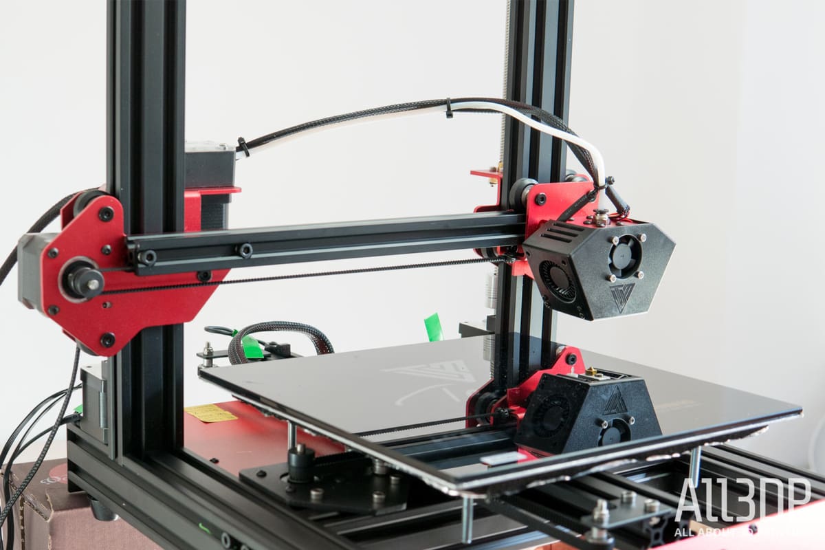
The print head scoots off to begin a print but somehow ends up in the wrong spot, or worse, misses the bed and keeps on going. If the miss is close to the edge of the print area, this can be accompanied by the alarming sound of the stepper motor skipping steps as the machine attempts to move beyond its physical limits.
Causes
Improper machine parameters
The G-code your slicing software creates is generated considering a given machine’s physical dimensions. If there’s a mismatch between your printer and the virtual printer your slicer used to prepare your print, the printer may attempt to move beyond its physical limits.
Loose belts
A 3D printer’s belts need to be tight on their pulleys and idlers to transmit the correct movement to the print head and bed. A loose belt may only partially catch on the pulley, delivering inconsistent movement that can result in improperly positioned prints and print-ruining artifacts like layer shift.
Solutions
Check your slicer settings
A quick thing to check is that you’re using the correct printer profile in your slicing software. It can be an easy (and easy to miss) mistake and takes mere seconds to check and rectify.
Check/tighten the printer’s belts
This is also an easy one to diagnose. A 3D printer’s belts for the printhead and bed motion should be tight enough that they stiffly resist you pinching them together, but not so tight that it requires a lot of force to do so. Alternatively, with the printer on but the stepper motors disabled, pinch one particular section of the belt and draw it back and forth. Observe the print head (or bed, whichever applies) to see if there’s any slop in the movement. There should be a direct transmission of movement.
Some printers feature belt tensioners at the end of each belt’s respective gantry. These typically require you to take an Allen key and tighten a machine screw, which physically repositions the idler and increases the tension. Other printers have thumbscrews for you to turn to tighten the belts.
Tip: Avoid overtightening the belts - they can stretch over time, and you'll only speed up the rate at which you have to retighten them.
Some manufacturers even recommend tuning the pitch of the belts’ tensions using a guitar tuning app. Prusa Research, for example, hosts a web app for just such a purpose, giving visual guidance to fine-tune belt pitch for its latest 3D printers. If you know the width and length of your belt, there are tools to tell you the optimal pitch to aim for.
Print is Stuck to Print Bed
Print bed adhesion can sometimes be a little too good. The print gets stuck, and you risk damaging your print or printer when you resort to brute force.
Causes
Poor bed level
If the gap between your nozzle and print bed is too small, your printer is forced to push more plastic than reasonably fits, hard, into the bed. This is particularly true of build plates with textured surfaces. Depending on the material printed, this can result in your print sticking too well to the bed and leaving trails of material fused to the bed that are difficult to remove.
Material/build plate incompatibility, and no glue
Using adhesive to help your prints stick to the bed is smart. Using adhesive to stop your prints from sticking to the bed with the power of a thousand gorillas is smarter. Some materials bond too much to particular print bed types. It’s not uncommon to see glass print beds splinter from print bed adhesion from materials as innocuous as PETG. Glue doesn’t just help your prints stick, it helps them unstick, too.
Solutions
Check & correct Z-offset
The classic, the reliable, “did you turn it off and on again?” troubleshooting tip in 3D printing – checking that your Z-offset is the best it can be really does cure many ailments in 3D printing. Prints that stick too well, particularly if you notice that the quality of your first layers is untidy, can mostly be cured by optimizing the gap between your nozzle and print bed.
Add glue
Applying a thin layer of 3D print adhesive to your print bed after every couple of prints helps prints adhere to your bed, but also acts as a terrific release agent. The bonding force is strong enough to see the print through, but weak enough for you to prise the print free once the print bed has cooled.
Tip: Many types of 3D printing glue are soluble, meaning you can dissolve the glue in situations where it doesn't come free by hand.
License: The text of "3D Printing Troubleshooting Guide: 30 Common Problems & Solutions" by All3DP is licensed under a Creative Commons Attribution 4.0 International License.
CERTAIN CONTENT THAT APPEARS ON THIS SITE COMES FROM AMAZON. THIS CONTENT IS PROVIDED ‘AS IS’ AND IS SUBJECT TO CHANGE OR REMOVAL AT ANY TIME.