Stop 3D Printing Failures With All3DP’s Ultimate Guide to Support Structures

Confidently tackle overhangs and bridges in your models with All3DP's ultimate guide to 3D printing support structures.
If you’ve had any experience with an FDM 3D printer, you’ve probably come across one or two occasions where you needed to make use of support structures. If you’ve ever had doubts, worries, or even full-blown print failures because of them, that ends now. This guide is all you need to know about support structures to feel confident using them, start to finish.
Support structures are considered a necessary evil in 3D printing. They are absolutely essential for models with steep overhangs or bridges, but they can frustrate by increasing material use (costs and waste), adding more post-processing work, and sometimes even damaging the model’s surface. Getting supports right is, therefore, a very important aspect of 3D printing complicated models.
This article breaks down every aspect of 3D printing support structures, from the types to the slicer settings, so you can print armed with the knowledge and confidence to get perfect 3D prints. Let’s get to it.

Support Structures: What They Are & When You Need Them
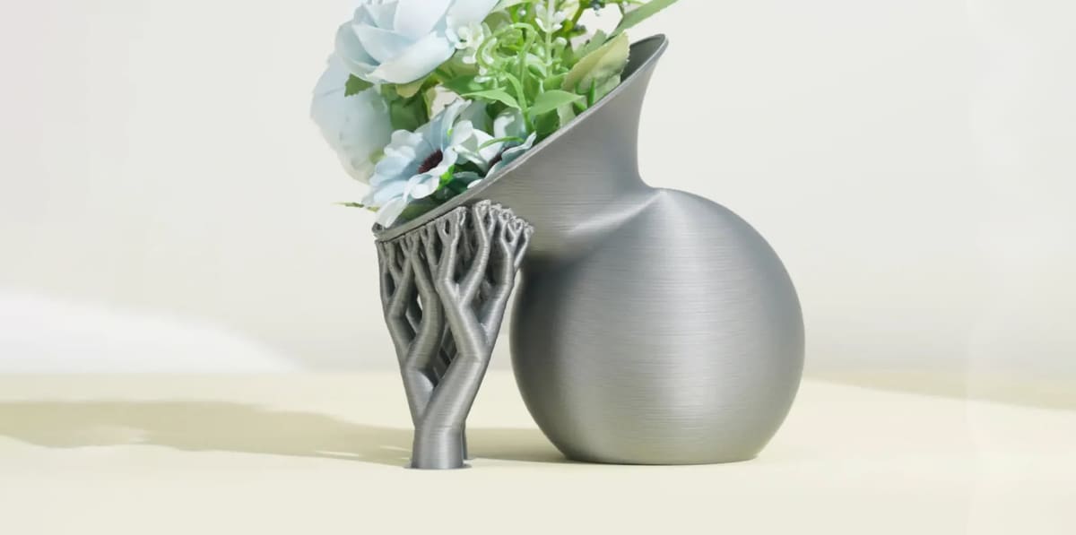
Support structures are temporary printed features that hold up parts of a model that would otherwise begin printing with insufficient material underneath them. They're most commonly needed beneath overhangs and, in some cases, bridges.
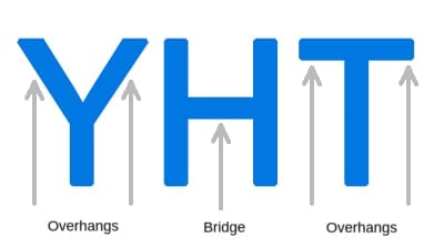
The Y, H, and T shapes below illustrate the basic situations. An angled overhang may remain partly supported by the previous layer, while a horizontal bridge spans between supported areas. A horizontal overhang that starts in mid-air has nothing beneath it and is much more likely to need support.
Overhangs: The 45 Degree Rule
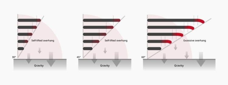
Not every overhang needs support. A commonly used starting point is the 45-degree rule: an overhang that extends up to roughly 45 degrees from the vertical can often be printed without support because each new layer still overlaps enough of the layer beneath it. However, many prefer a smaller degree. Bambu Studio’s current “threshhold angle” is set to 30° by default when automatic support generation is enabled. Users can adjust that angle, select “support critical areas only,” or tick the “remove small overhangs” box, which identifies small areas that technically count as overhangs but are likely able to print without support, and it suppresses support underneath those areas. This can reduce unnecessary little support towers, save material, shorten print time, and leave fewer support marks on the model.
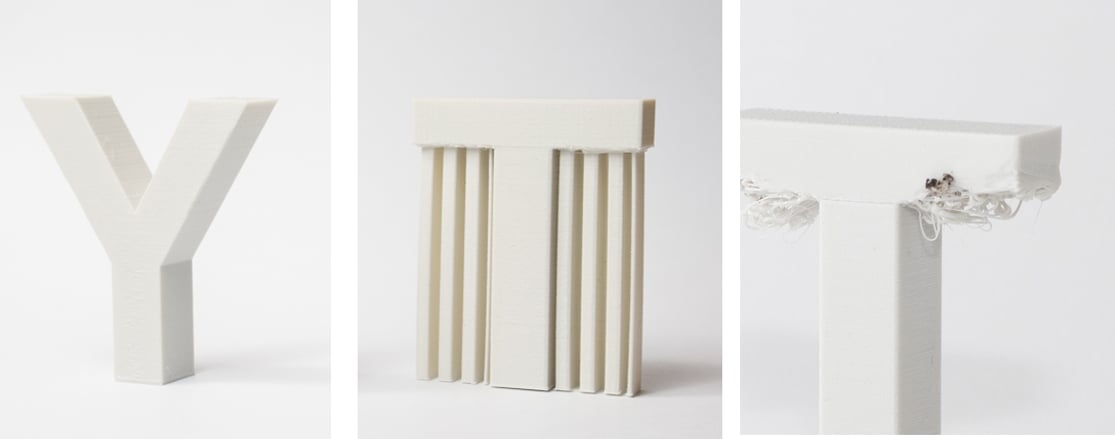
The horizontal arms of the T are different. They form a 90-degree overhang from the vertical, leaving the first layers with little or nothing beneath them. Without support, those extrusion lines would effectively be printed into mid-air, making sagging or print failure much more likely.
However, 45 degrees isn’t a hard limit. How steep an overhang your printer can handle depends on factors including layer height, line width, print speed, cooling, material, nozzle size, and the printer itself. Some well-tuned machines can produce good results at significantly steeper angles, while others may begin to struggle sooner.
It’s also worth paying attention to how your slicer defines its overhang angle. Different slicers and printer profiles don’t necessarily treat 45 degrees as a universal cutoff.
So, consider 45 degrees a useful rule of thumb rather than a guarantee. If surface quality is important, print an overhang test with your chosen material and profile to find out what your particular setup can reliably handle.
Bridges: Is There Really a 10 mm Rule?
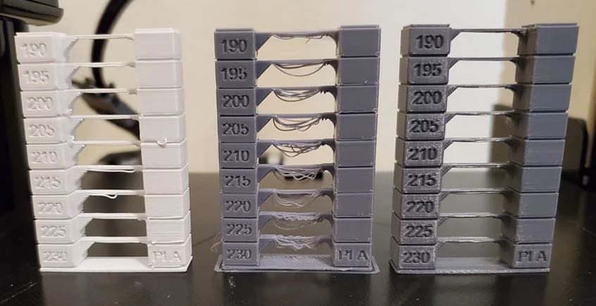
A bridge is a section of a print that spans a gap between supported areas. Instead of depositing filament directly onto the previous layer, the printer stretches each new line across the gap. In short, well-tuned bridges can often print successfully without support.
The general rule of thumb that if a bridge is less than 10 mm in length, the printer may be able to print it without supports, is more of a guideline that a fixed rule. How far your printer can bridge cleanly depends on factors such as the printer and hot end, filament, cooling, bridge speed and flow, nozzle and layer height, and the shape and width of the span. A distance that prints easily on one setup may sag badly on another.
If your slicer offers dedicated bridge settings, speed, flow, and cooling are useful places to start. PLA often benefits from strong bridge cooling, while materials such as ABS and ASA generally require a different cooling balance to avoid warping or poor layer bonding. Use the material profile as a starting point rather than applying one cooling rule to every filament.
For important parts, print a bridge test and judge the surface quality you actually need. A bridge doesn’t have to fail completely to be unsuitable: excessive sagging or a rough underside may be enough reason to add support.
If you want to know which settings to tweak, check out our 6 tips for perfect bridges, but here are the tips in a nutshell:
- Lower the Print Head Temperature
- Increase Cooling Fan Rate
- Decrease the Extrusion Multiplier
- Decrease Printing Speed
- Buy High-Quality Filament
- Use Dry Filament
First, Test Your Printer’s Capabilities
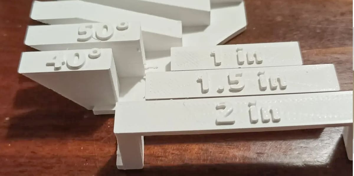
Rules such as 45° for overhangs are useful starting points, but your practical limit for supports depends on a number of factors, including your:
- printer
- filament
- cooling fan speed
- layer height
- print speed
- model geometry
An overhang or all-in-one calibration model can quickly show you where surface quality begins to deteriorate on your printer using your filament. Don’t look only for complete print failure: if an overhang becomes rough or a bridge sags more than your part can tolerate, you’ve already passed the useful limit for that application.
Remember that the result applies to the combination you tested. Changing filament, nozzle size, layer height, cooling, or the print profile can change your overhang and bridging performance, so it can be worth retesting after major changes.
If you want to test you printer for overhangs, just download and print this overhang test model. This model has a series of overhangs ranging from 20 to 70 degrees at 5-degree increments. To test bridging, this shell-shaped design will show how far the envelope can be pushed. Alternatively, you can always use general print calibration models that also include bridges and overhangs.

Selecting a Support Type: Normal or Tree?
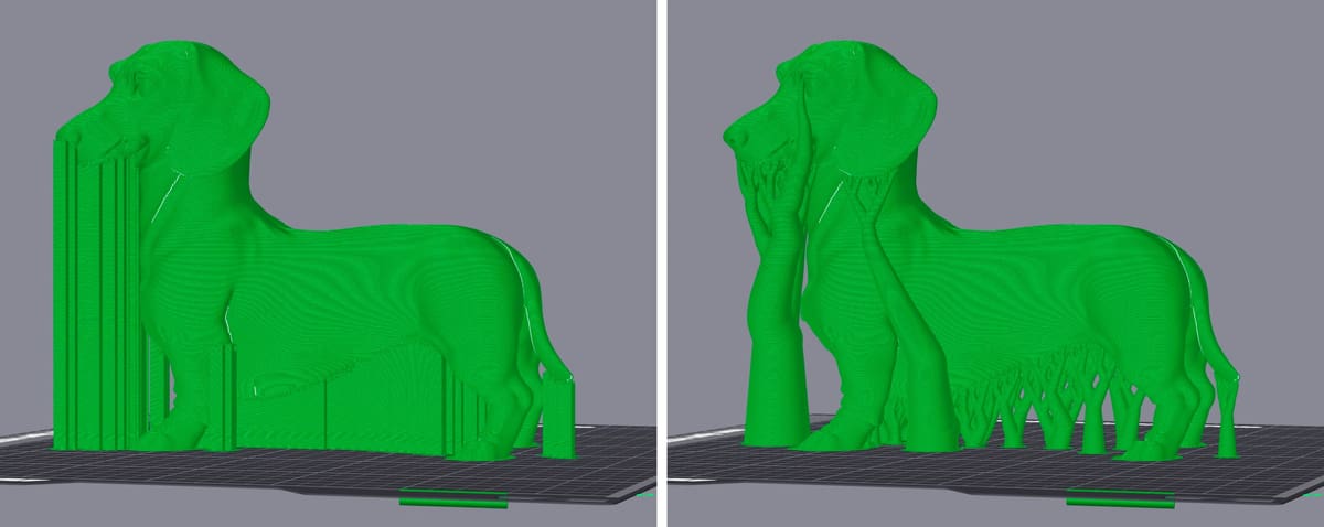
There are two common types of support structure — normal and tree — with one extra support structure using a bit of both, known as hybrid supports, but among those, there are dozens of way to manipulate them depending on which slicer software you’re using.
Tree and organic support can reduce material use and contact with the part, especially on irregular geometry, but they aren’t automatically best for every shape. Conventional support can still be advantageous beneath broad, flat surfaces or where a very stable support structure is needed.
Different slicers express themselves in different ways, and as we can’t explain every single one here without writing an entire white paper, we recommend checking out these below:
Guide to Slicer Settings In:
Normal/Lattice Support
Also known as linear, “normal” supports consist of vertical pillars that touch the entirety of the overhang. This type of 3D printing support works for just about every overhang and bridge. However, they can be much harder to remove and much more likely to cause damage to the model surface.
You can adjust the settings of your normal supports to reduce the number of supports and the amount of material they consume. For example, you can set you slicer to only support areas with a less than 15% overhang and set your normal support pattern to “hollow” like in the example below. Each slicer program will have it’s own settings but they’re are all very similar. We have a guide to Bambu Studio settings at Bambu Studio: Support Settings – Simply Explained.
Tree/Organic Support
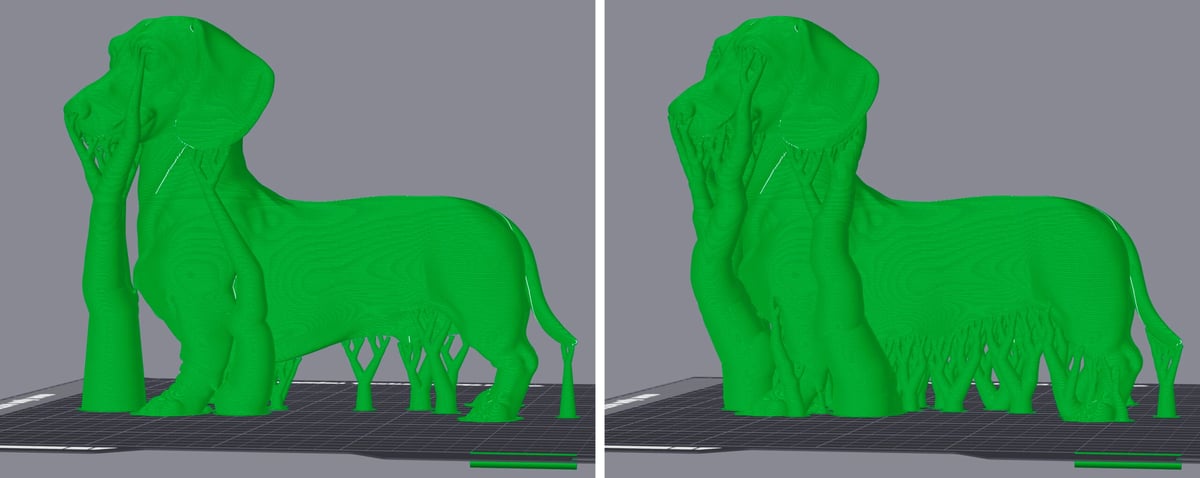
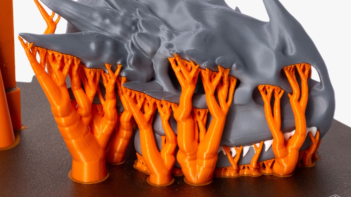
Tree-like supports look like their name suggests. This type of 3D printing support only touches the overhang at certain points.
One of the biggest advantages of tree-like or organic supports is that their branches can route around the model and make contact only where support is needed. This can reduce material consumption, printing time, surface marking, and the amount of support that needs to be removed.
They are especially useful for figurines, curved surfaces, and complicated geometry, but modern implementations aren’t restricted to organic shapes. Depending on the slicer and model, tree or organic supports can also use dense interface layers and support a much wider range of geometry than older tree-support systems.
For broad, flat overhangs, conventional support may still provide the simpler or more rigid solution. Some slicers and workflows also allow support strategies to be mixed or applied differently to individual areas, so the best choice depends on the geometry rather than one support style always being superior.
Hybrid Support
There’s nothing particularly complicated to hybrid supports. The software simply makes use of both linear and tree-like supports in order to provide the best of both worlds for the model.
You might need the strong, stable linear supports for some big overhangs in one part, but rely on the lightweight, easy-to-remove in other sections. Hybrid support means you can do this, and get the benefit of using both instead of just one.
Minimize Supports Through Design
Integrate supports into the model

One trick to get around support structures is to add elements to the model that perform the same job. This technique has been used by sculptors for centuries, as Antonio Canova demonstrated below with his “Venus Vitrix” sculpture.
Here, the right arm is an overhang, but it is supported by the pillows. The left leg is another overhang, but this time the bunched togas act as the support.
Integrating support structures into the design is more of an art than a science. You need to come up with elements that simultaneously fit into the overall design and can support the overhangs or bridges. When done correctly, it enhances the beauty of the model and makes the print process free of support structures – saving time, money, and labor.
Chamfers
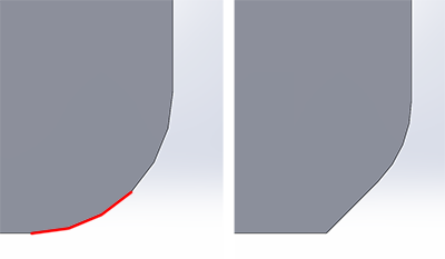
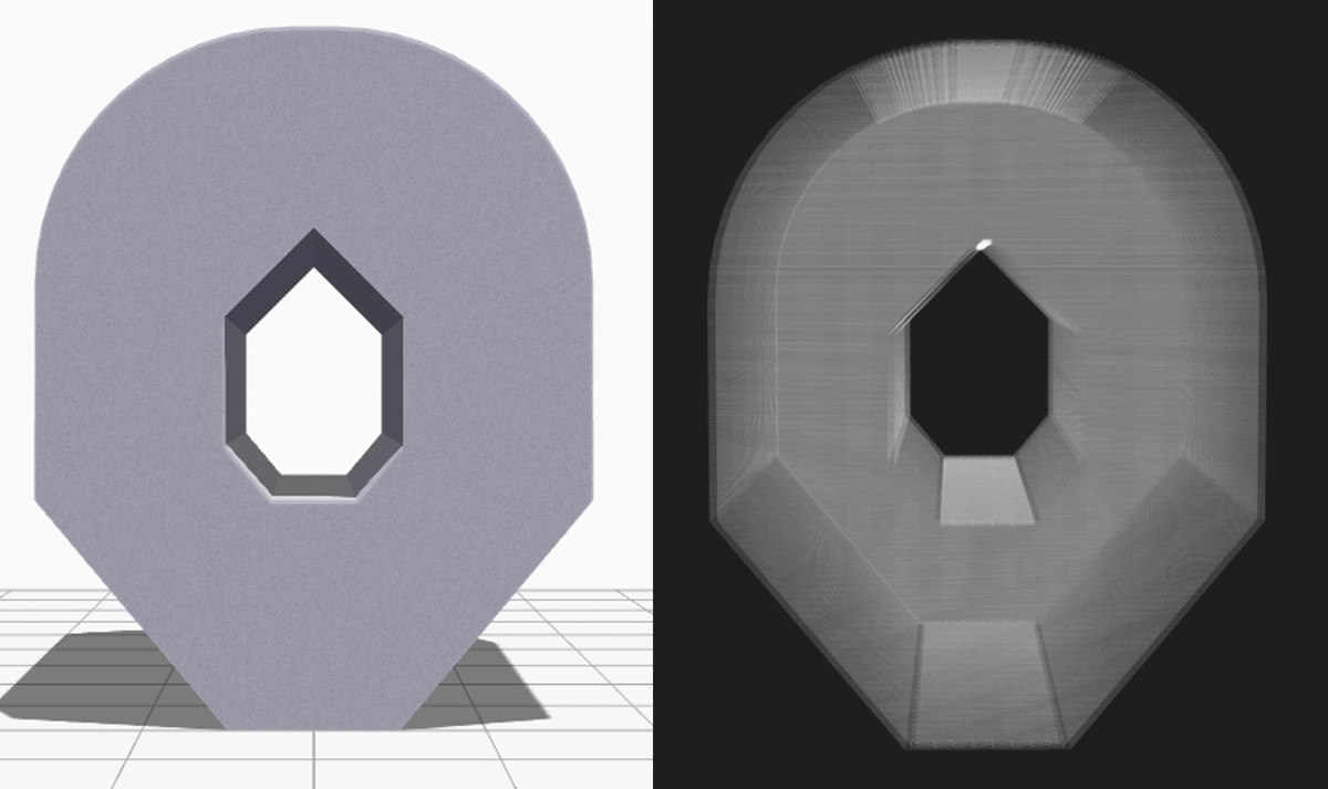
Another way to eliminate supports is chamfers. Chamfers are a neat way of turning otherwise nasty overhangs into innocuous overhangs with angles less than 45 degrees.
For example, if you have a gently sloping or curved edge, you can replace it with an angular edge that requires no support. Such an angular design is called a chamfer.
Split the Model into Pieces
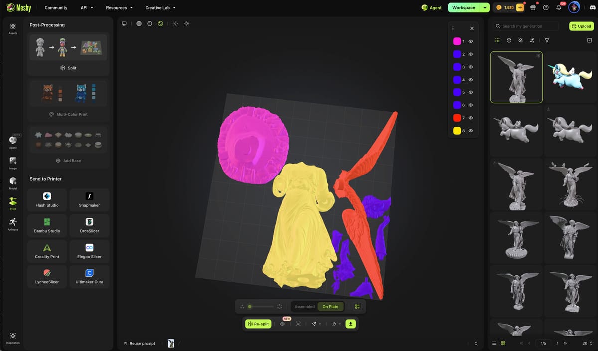
Sometimes the easiest way to avoid a difficult support problem is to stop printing the object as one piece.
Splitting a model can allow previously unsupported surfaces to lie flat on the build plate. Parts can then be joined with glue, screws, pins, dovetails, sockets, or other alignment features depending on the application.
This introduces an assembly step and potentially a visible seam, but it can produce much cleaner surfaces than printing a heavily supported one-piece model. It’s particularly useful when the natural split can be hidden along an existing edge or feature.
Check out our guide: Print Big Parts on Small Plates: How to Split Your STL in Bambu, Prusa, Orca & Cura Slicers.
Reorient the Model
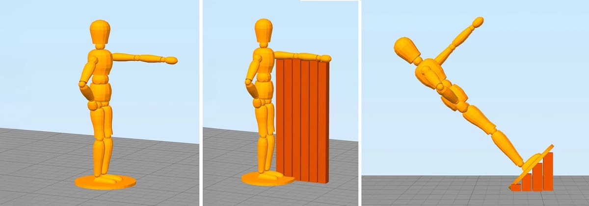
Sometimes, minimizing the necessary support structures is as easy as reorienting the model on the print bed. For example, it is much better to print the open box shown below with the open face on the top.
Consider the example of this human figurine, for example. If you print the model as it is, we will need to support the left arm. It is basically a long overhang with an angle of 90 degrees.
When you remove the supports, it will most likely leave blemishes on the underside of the arm. To avoid that, you can rotate the whole model by 45 degrees and just add support for the base of the model. The quality of the base of the model does not matter much anyway. This way, you can print the model with fewer support structures and save the left arm from damage.
This model is only a demonstration. More experienced makers among you will see the little “islands” at the knee, buttocks, and head where the print head would extrude into nothing and therefore result in a pretty ugly print. Of course, these islands would also need to be supported in order to avoid this.
6 Important Slicer Settings for Supports & How They Work
Today’s slicers provide a large number of support controls, but only a handful have the biggest effect on where supports appear, how well they work, and how easily they’re removed.
We’ll use Cura terminology where useful because it’s widely recognized, but other slicers offer comparable controls under different names. It’s also important to distinguish between the support structure itself—such as Normal or Tree in Cura—and the support pattern, which determines how applicable conventional support is filled.
The defaults are often a good starting point. Change settings to solve a particular problem rather than assuming that denser, closer, or more extensive supports are automatically better.
After every significant change, slice the model and inspect the supports in Preview. Looking at the actual generated toolpaths is much more useful than judging a support setting by its numerical value alone.

Auto-Generate or Manual?
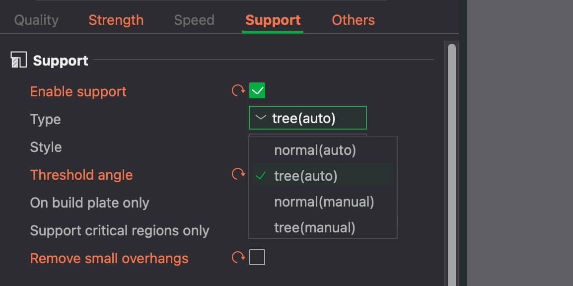
How do you know where your model may need support?
Most slicers can highlight overhangs while you’re preparing the model. In Cura, areas that exceed the configured overhang threshold are shown as overhanging surfaces, making it easier to spot parts of the model that may need additional support.
Don’t assume that every highlighted area automatically needs it, though. Surfaces at the bottom of the model may already be supported by the build plate, while small spans across holes or gaps may be printable as bridges. As we’ve seen, whether an overhang or bridge actually needs support depends on your printer, material, settings, and the surface quality you’re aiming for.
Pay closer attention to highlighted areas that begin above open space with little or no material beneath them. These are the places where support is most likely to be necessary.
To have Cura create supports automatically, enable Generate Support in the Support settings. Cura will then generate support beneath the areas that meet its support criteria, according to settings such as the overhang angle, support placement, and the selected support structure.
Don’t stop there. Automatic support generation is a starting point, not a guarantee that the result is ideal.
After slicing, switch to Preview and inspect the generated support together with the model. Move through the layer slider to see where support begins, how it reaches the overhangs, and whether it has been generated inside holes, cavities, or other areas where it could be difficult to remove.
Preview is also useful for spotting the opposite problem: an important overhang that hasn’t received enough support. If the automatic result doesn’t make sense, go back and adjust the relevant support settings before printing.
Modern slicers also give you ways to override automatic decisions. Support blockers or enforcers, paint-on or manually defined support tools, and per-object settings can help remove unnecessary supports or add them only where they’re actually wanted. The exact tools and names vary between slicers.
Support Structure Placement
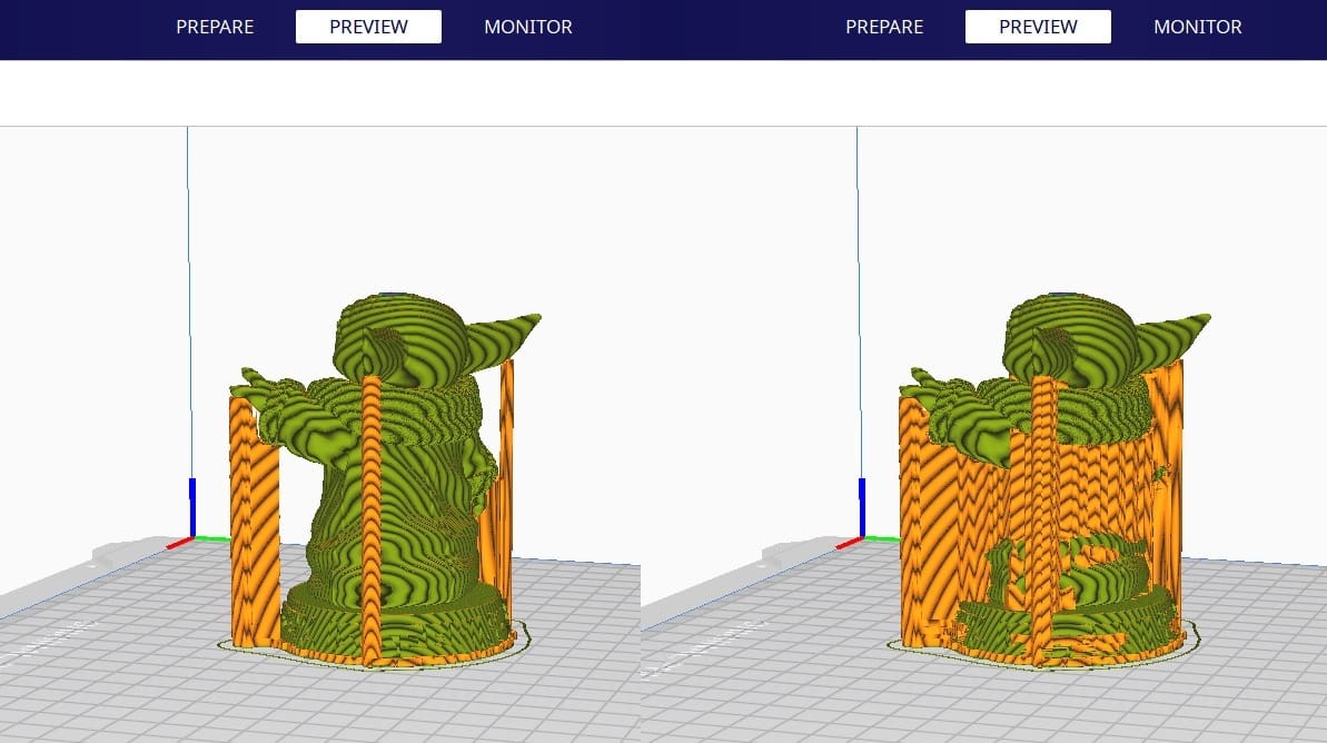
Support placement controls where the slicer is allowed to generate support, not simply how much support it creates.
A build-plate-only option restricts supports to structures that can ultimately reach the build plate. This can reduce material use and prevent support from being built directly on top of visible model surfaces, making cleanup easier.
The disadvantage is that an isolated overhang above another part of the model may receive no support at all if the slicer can’t route a structure to it from the bed.
An everywhere-style option allows support to begin on the model as well as the build plate. This can support more difficult geometry, but it also increases the chance of support marks and structures that are awkward to remove.
Choose the option based on the model and inspect the result in Preview rather than assuming build-plate-only support is always preferable.
Enable Support Roof
In Cura, a Support Roof is part of the broader Support Interface system. It’s a denser layer between the main support structure and the underside of the model, giving the first model layers a more consistent surface to print on.
A support roof can significantly improve the finish beneath an overhang compared with printing directly over a sparse support pattern. The trade-off is that, with same-material supports, a dense interface or very small contact gap can make support harder to remove.
Interfaces are also useful for multi-material printing. A soluble or breakaway material can be used only at the model-contact layers while the bulk of the support remains in the model material, reducing the amount of specialist filament required.
X/Y Distance Setting
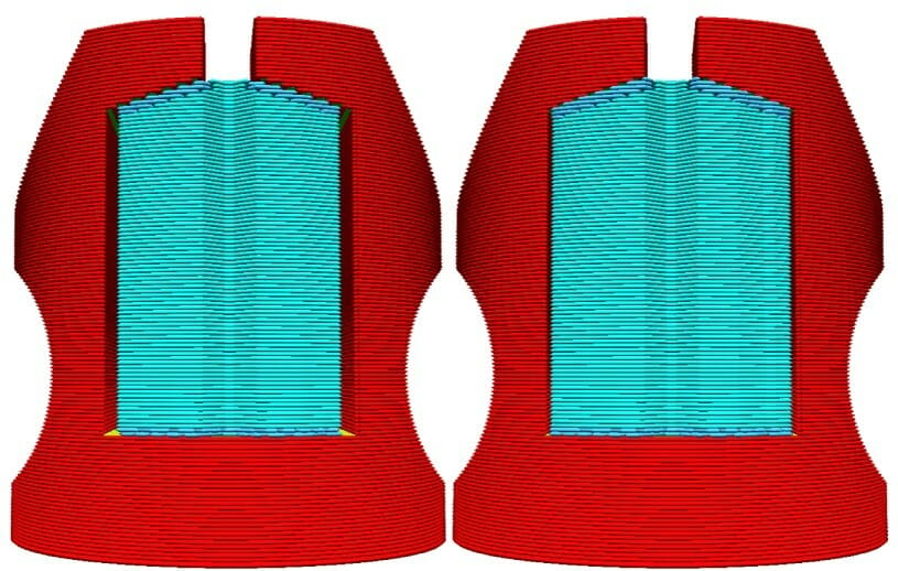
Sometimes, the supports are built too close to the model’s outer wall and leave marks on its outer surface. You can prevent this from happening by using the Support X/Y Distance hidden setting under the Support section.
The Support X/Y Distance setting in Cura essentially controls the minimum allowed distance between the model’s vertical walls and a support structure in the X/Y plane. If your support structures are damaging the walls or sticking to them, you can increase the value by increments of 0.2mm until the walls come out smooth. However, please ensure that there are no small overhangs sticking out of the outer walls that will go unsupported if you put a little bit of distance between the support and the walls.
Z-Distance
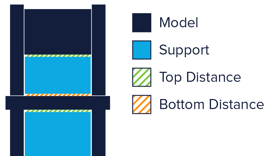
Z distance controls the vertical separation between a support structure or interface and the model.
This is one of the most important settings for balancing surface quality against easy support removal. A smaller gap gives the first model layer above the support less room to sag, usually producing a cleaner underside. Make the gap too small with same-material support, however, and the support may fuse strongly to the part.
A larger gap makes support easier to remove but generally produces a rougher supported surface.
The ideal value depends on layer height, printer calibration, material, interface settings, and the slicer’s own contact-distance behavior. For that reason, fixed values shouldn’t be treated as universally correct.
Multi-material interfaces change the equation. With a compatible soluble or breakaway interface material, little or no Z separation may be possible because the interface doesn’t need to snap away from the model in the same way as a same-material support.
If supported surfaces are consistently rough, reduce the gap cautiously or improve the interface. If supports are fusing to the model, increase the separation and check extrusion accuracy before making other support structures denser.
Support Pattern & Density

Support pattern describes the arrangement of lines inside conventional support structures. This is different from the overall support structure or style, such as Normal versus Tree.
Patterns trade strength, material use, print time, and removability against one another. Sparse or simple line patterns generally use less filament and can be easier to break away, while more interconnected patterns provide greater stability for tall or heavily loaded supports.
Support density or pattern spacing controls how much material is placed in the main support body. Higher density can make support more stable and give interface layers a better foundation, but it increases print time and usually makes removal more difficult.
Don’t automatically increase the density to improve the supported surface. In many cases, adding or tuning a support interface is a more efficient way to improve the contact surface while leaving the bulk of the support relatively sparse.
Support Structures: The Downsides
As with anything in life, support structures have their downsides. There are a few to go through here, so allow us to explain.
Increased Material Cost
If you’re using 3D printing in a production setting, you probably only care about the cost per part. Same if you’re a hobbyist on a budget.
3D printed support structures obviously add to the production cost of the model. Support structures consume material, and this material is later removed and discarded. So, every bit of support material that you use is essentially waste, and adds to the cost of the print.
When printing with specialized materials like carbon-fiber-reinforced filaments, costs can quickly ramp up. It might be worth looking into material management systems or dual extruders that allow the machine to switch between different materials.
Increased Print Duration
Another cost factor to consider is the increased print duration that comes with support structures. While FDM 3D printers do not cost a ton of money to operate, print times can quickly add up, especially when it comes to volume production.
On the other hand, minimizing support structures may not always be the quickest solution. If you want a one-off part it might make more sense to use more supports than theoretically needed for a successful first try rather than failing and having to print the same part several times.
How much it will cost therefore depends on how many parts you want to produce, how many supports are required, at what speeds you are printing them, and, how easily they can be removed.
Additional Post-processing
Support structures are not part of the model. They are used to support overhanging geometries during printing. This means that once printing is over, you have the additional task of removing the structures before the model is ready to go.
In a production setting, added work means added cost. This can add up further when support structures are in hard-to-reach places, do not easily separate from the actual part, or removing them causes parts of the model to break.
To minimize post-processing, you might want to consider switching to soluble supports. Alternatively, you might be able to get rid of them entirely by integrating supports into the design or reorienting the model.
Risk of Damaging the Model
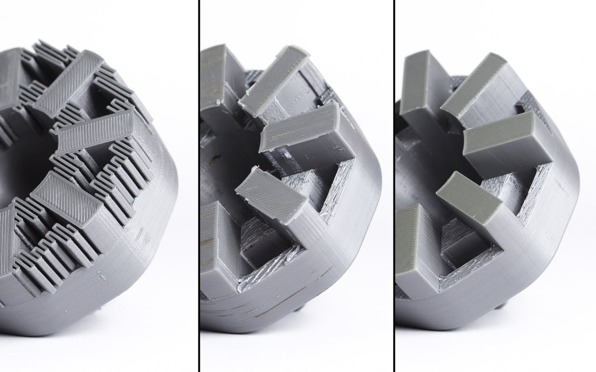
All in all, there are significant downsides to using support structures. Therefore, here’s another rule of thumb: minimize the use of support structures and add them only where necessary. In later sections, we will show you how to apply this philosophy right from the CAD design phase leading all the way up to the printing phase.
License: The text of "Stop 3D Printing Failures With All3DP’s Ultimate Guide to Support Structures" by All3DP is licensed under a Creative Commons Attribution 4.0 International License.