Fix Your Fails: The 10 Best Models to Calibrate Your Resin 3D Printer

Even resin 3D printers need a workout from time to time. Discover the best resin test print models to whip your machine into shape!
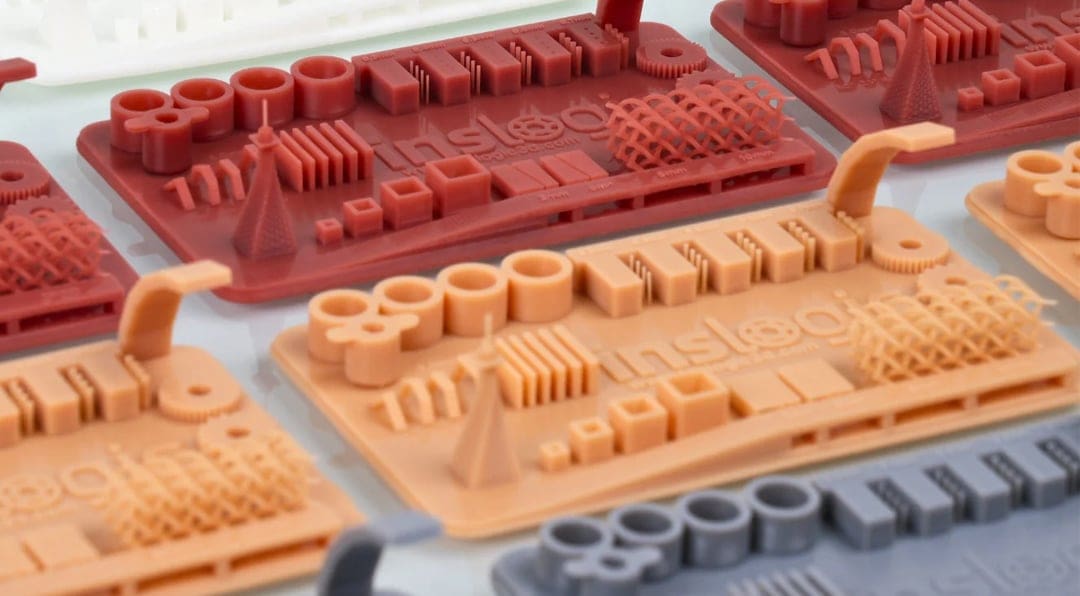
Ever spent hours waiting for a resin print to finish, only to find flaw after flaw appear on your build plate? It’s happened to the best of us. Even with the best resin printers, if the settings are off, you’re not going to get a good print. The good news is, a simple calibration model can quickly diagnose the problem and get you back on track.
While the classic Benchy is the ideal model for diagnosing issues with your FDM 3D printer, it won’t work for your resin 3D printer, and there’s no direct universal equivalent.
So here, we’ve hand-picked our 10 favorite test models to help you fine-tune your settings, diagnose your print flaws, and create fabulous prints every time.
These calibration models usually use up only small amounts of resin, so they can be great for checking if your settings are suitable for your selected resin or evaluating the shrinkage of prints before starting with larger or more detailed models.
Although there are different resin printing technologies differentiated by the light source used; stereolithography (SLA), digital light processing (DLP), and liquid crystal display-based (LCD), you dont’ need different calibration prints. These below will work on all type of resin 3D printers. Each model tests specific settings, and there are many options to choose from.
Despite their differences, all resin printing relies on common settings and factors for a good print, namely:
- exposure time
- resolution
- layer adhesion
- anti-aliasing
- resin quality
Let’s get your printer dialed in and your prints perfect!

Interpreting Results
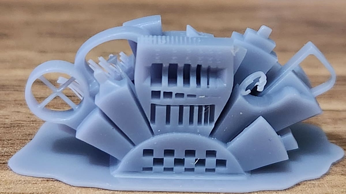
Before we dive into the models, it’s important to know what you’re looking at when assessing a printed calibration model. A calibration print isn’t simply a pass or fail. Think of it as a collection of clues: holes, pins, lettering, bridges, and flat surfaces each reveal something different about your settings.
Before inspecting it, wash and dry the model thoroughly. Liquid resin trapped inside narrow gaps can make correctly printed openings look blocked. You should also check the model designer’s instructions, as every test has slightly different targets and every printer-and-resin combination has its own ideal settings.
Start With Exposure
A useful rule of thumb is: too much exposure adds material, while too little exposure takes it away.
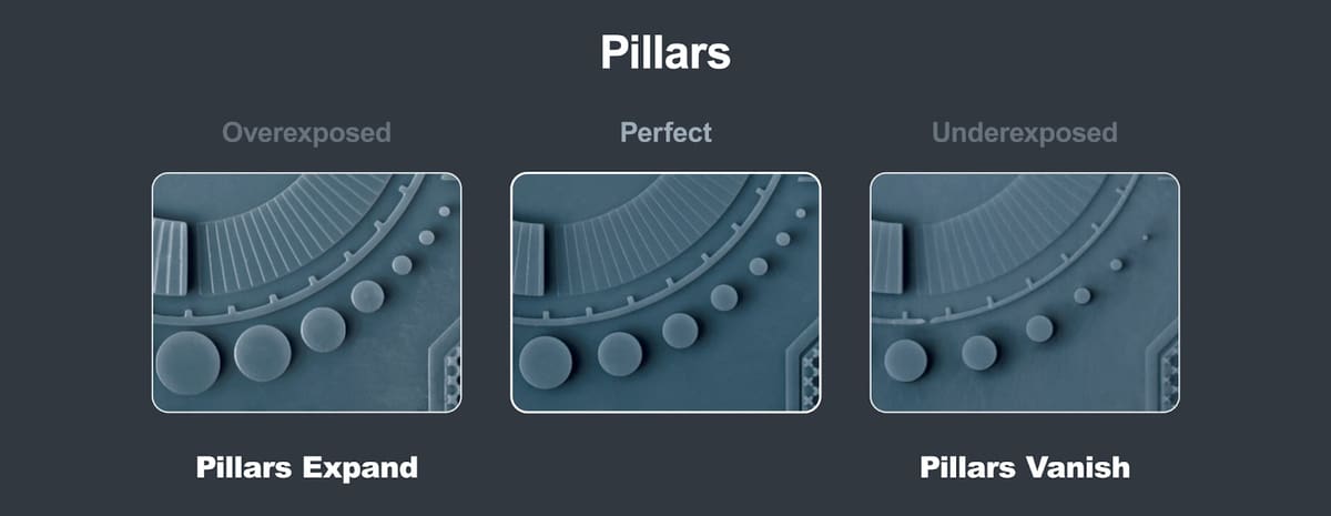
- Signs of overexposure: Raised lettering, pins, and lines look swollen or thicker than intended. Separate shapes begin to merge, while engraved text, holes, and narrow slots become smaller or close completely. Outside dimensions may also be slightly oversized. Reduce the normal-layer exposure time and test again.
- Signs of underexposure: Small pillars, dots, thin walls, and lettering are missing, weak, or partly formed. Holes and recessed details may look too large, while delicate features can bend or break away. Increase the normal-layer exposure time slightly.
- Signs that exposure is close to ideal: Raised and recessed lettering are both sharp, lines remain separate, and small holes stay open. On tests containing matching positive and negative details, such as pins and holes, roughly the same number of each should print successfully.
Don’t judge exposure by one feature alone. For example, a longer exposure might produce every tiny pillar but also fill in the holes and blur the text. Some resins are simply too soft or flexible to reproduce the smallest unsupported features, so aim for the best overall balance rather than the greatest number of surviving details.
Other Defects and What They Mean
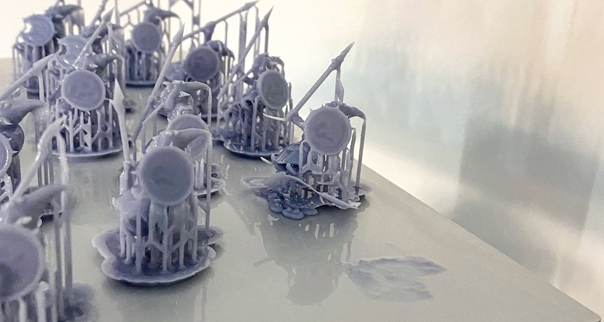
The base is swollen or extremely difficult to remove: The bottom layers may be overexposed. Reduce the bottom exposure rather than changing the normal-layer exposure used for the rest of the model.
The raft or entire model detaches from the build plate: Bottom exposure may be too low, but also check that the build plate is clean, correctly leveled, and firmly secured.
Bridges sag or thin towers bend: This can indicate underexposure, but it may also show that the resin lacks the strength needed for unsupported features. Fast lift movements and strong peeling forces can make the problem worse. Check the other exposure features before increasing the exposure time.
Flat areas curl, bow, or warp: This usually points to resin shrinkage, insufficient support, an unsuitable orientation, or large solid cross-sections rather than exposure alone.
Horizontal lines appear across the model: One or more layers may not have formed consistently. Possible causes include incorrect exposure, insufficient lift height or rest time, weak supports, suction inside a hollow model, or a worn release film.
Parts of the model shift sideways: Check the supports and hollowing setup, as sudden changes in suction force can move the print. Loose build-platform, tank, or Z-axis components can also produce skewed or doubled details.
Random holes or pits appear where the model should be solid: These are different from the deliberately modeled test holes. They usually indicate cured particles, dirt, or another obstruction between the light source and resin. Filter the resin and inspect the vat film before printing again.
The dimensions are consistently too small after curing: Exposure can affect the size of individual holes and raised features, but uniform dimensional loss is more likely to be resin shrinkage. Use a dimensional calibration model and the slicer’s shrinkage or tolerance compensation instead of increasing exposure.
Change only one setting at a time and print the same test again. Most importantly, treat normal exposure and bottom exposure as separate adjustments: one controls fine details throughout the model, while the other mainly controls adhesion to the build plate.
Best All-Purpose Test Print: AmeraLabs Town
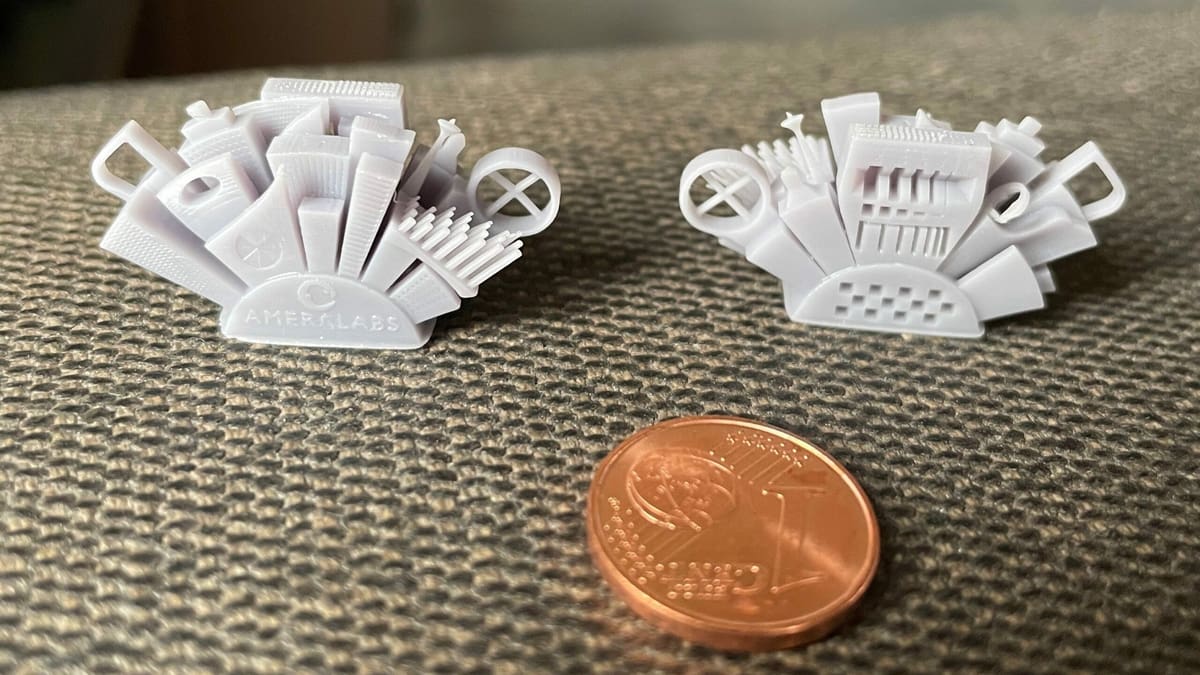
Designed by AmeraLabs, a Lithuanian resin manufacturer, the Town is an all-purpose calibration part that tests printer settings and resin quality. In total, there are 10 different tests integrated into the model, as indicated by the various buildings protruding at various angles. Its effectiveness makes it the frequent subject of resin printing videos and tutorials.
The first test consists of varying slot widths, ranging between 0.1 and 1 mm, that test the quality of the printer’s light source as well as exposure times for curing each layer. The second test has various opening heights that test for exposure time and layer adhesion based on the visibility of the openings. The third test is a cross-shaped bridge formed by two intersecting pillars. If this part of the model shows any deformations or inconsistencies, it may point to potential issues with the layer height or even the resin being used. These are only 3 of the 10 tests, and already, they tell you a lot about your resin printer’s performance.
- Who designed it? AmeraLabs
- How printable/popular is it? The Town model has 15 makes and over 47,000 downloads combined from Thingiverse and MyMiniFactory – it’s definitely popular.
- Where to find it? Thingiverse, MyMiniFactory
Perfect For Quick Troubleshooting: Siraya Tech

Siraya Tech, a Hong Kong-based resin manufacturer (formerly part of Peopoly), designed their own test model, which contains five sections, three of which test the printer’s exposure settings. As a quick troubleshooting tool, both exposure and resolution can be tested even when the model isn’t completely printed.
Already at 3.5-mm height, the pinhole, recessed texts, and the triangular and circular objects should be visible. If you allow the rest of the model to print, the remaining features (the cube and the arch) test for printability and anti-aliasing properties.
- Who designed it? Siraya Tech
- How printable/popular is it? This model has over 48,300 views and more than 7,000 downloads on Cults.
- Where to find it? Siraya Tech, Cults
Test For Build-plate Leveling: J3D Tech’s Build Plate Calibration
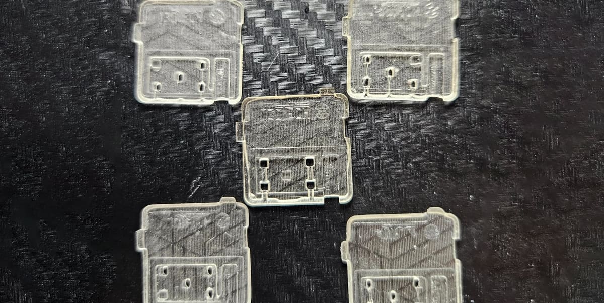
Correct exposure settings won’t help if the build plate is tilted or starts at the wrong height. J3D Tech’s Build Plate Calibration uses five thin test pieces—one at the center and one at each corner—to check plate leveling, Z offset, and burn-in adhesion in a print that should take around 15 minutes or less.
After washing and curing the pieces, measure their thinnest sections with digital calipers. If all five measurements are within 0.15 mm of one another, the plate is sufficiently level. A larger difference suggests that it should be leveled again. Without calipers, you can connect the four corner pieces using their notches and feel for obvious height differences, although this method isn’t accurate enough for setting the Z offset.
For the Z-offset check, the marked section of each piece should measure 1 mm thick. Average the five measurements and compare the result with this target. A value below 1 mm means the first layers are being compressed because the plate starts too close to the release film. Adjust the Z offset by the measured difference and repeat the test, keeping in mind that the adjustment direction varies between printers. J3D Tech considers results around 0.1–0.2 mm above the target generally acceptable.
A correct Z offset helps prevent compressed parts, split rafts, incomplete layers, and missing supports or fine details. The test also provides a rough burn-in check: all five pieces should stay attached during printing without being excessively difficult to remove. Normal-layer exposure should still be calibrated separately.
- Who designed it? J3D Tech
- How printable/popular is it? Around 9,000 downloads, 64,700 views, and 170 likes on Cults
- Where to find it? Cults
For Testing Tolerances and Viscosity: Hidden City Calibration Cube
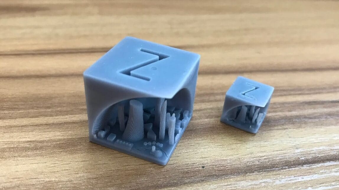
In 3D printing, calibration cubes are popular for fine-tuning printer settings. But what if a calibration cube held a secret? Take a look at the Hidden City Calibration Cube – a creation that cleverly hides a cityscape within. The designer combined a calibration cube with a skyline model, ingeniously hiding the intricate cityscape within the cube’s standard 20-mm size.
Initially designed for printing in PLA, the designer suggests trying the test with resin. With its remarkable property for capturing intricate details, resin elevates the fine details of the cityscape. When tested by enthusiasts like Bastock on a resin printer, the results were excellent, with great detail and depth on the first attempt.
The compact buildings inside the city allow for testing tolerances and resin viscosity, providing insights for adjustments. Also, as buildings are closely packed within this compact cube, you can see how resin behaves in complex spaces. By observing the results, adjustments to pigment concentration or exposure settings can be made to achieve sharper, more defined building structures.
- Who designed it? jq910
- How printable/popular is it? This model has been downloaded over 3,200 times and 9 makes have been shared on both sites combined.
- Where to find it? Thingiverse, Printables
For Bottom Layers & Elephant Foot: Bottom Exposure Calibration
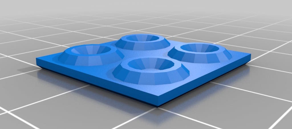
Bottom, or burn-in, layers need enough exposure to anchor the print to the build plate, but more isn’t always better. Excessive bottom exposure can produce a swollen edge known as elephant foot, make parts difficult to remove, and place unnecessary strain on the release film and screen.
Designed by Thingiverse user waever, the Bottom Exposure Calibration model provides a quick, low-resin way to find the shortest exposure time that still produces reliable adhesion. Place copies of the model at the center and corners of the build plate, then print several tests while gradually reducing the bottom exposure time. The best setting is the lowest value at which every piece remains fully attached.
If one or more pieces lift or detach, increase the bottom exposure slightly. If they stay attached but have noticeably swollen edges or require excessive force to remove, reduce it. Elephant foot can also be made worse by an incorrect Z offset or by exposing the resin before the build plate has completely settled, so check those settings if lowering the exposure doesn’t solve the problem.
Transition layers gradually reduce exposure between the burn-in and normal layers. This model doesn’t produce a single correct transition-layer value, so calibrate bottom exposure first. Start with no transition layers and add a small number only if the print separates where the burn-in layers meet the normally exposed layers. Repeat the test after every adjustment and change only one setting at a time.
- Who designed it? Waever
- How printable/popular is it? A small, free model intended specifically for resin build-plate adhesion and bottom-exposure calibration
- Where to find it? Thingiverse
Best for Support Strength and Functional Fit: Cones of Calibration V3
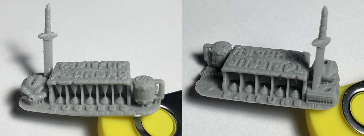
While most calibration models focus on detail or dimensional accuracy, Cones of Calibration V3 tests whether small support-like connections are strong enough to survive printing. This makes it especially useful for pre-supported miniatures and other models that rely on fine support tips.
The model includes “success” cones that should connect and “failure” cones that should remain separate. If the success cones fail, exposure or support strength may be too low. If the failure cones connect, excess curing may be thickening features and closing gaps.
V3 also includes practical fit tests. Removable parts, including the Ale of Accuracy and Sword of Truth, check whether pins, sockets, and multipart prints will fit together correctly. Wash and dry the model before testing these parts, but don’t post-cure it first, as curing can change the fit.
If the fit tests pass but the smallest success cones still fail, the resin may be accurate but too weak for very fine support contacts. In that case, stronger supports or a tougher resin may work better than increasing exposure further.
- Who designed it? TableFlip Foundry
- What makes it different? It combines support-tip survivability with real clearance and mating-part tests
- Where to find it? TableFlip Foundry
Perfect for Prusas: Prusa SL1 Calibration Object
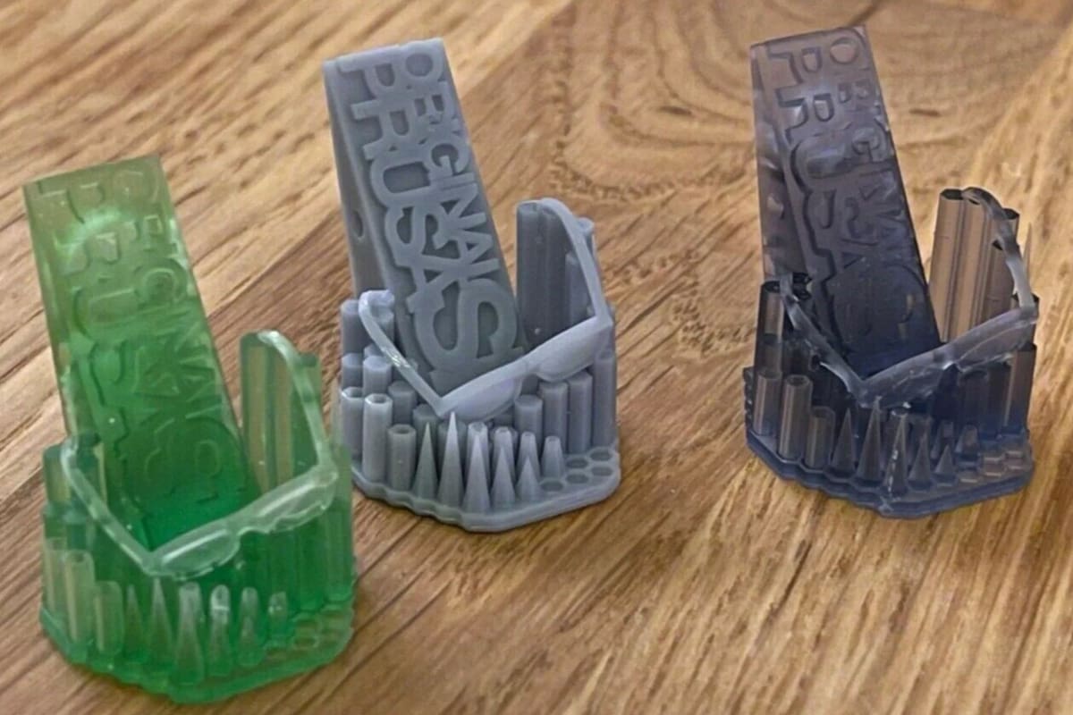
Although Prusa, a mainstay in the FDM printing community, came a little late to the resin printing scene, they’ve developed their own unique calibration model for the Prusa SL1 and SL1S. The model even comes preloaded on all SL1 printers. After printing it, users should look for issues such as missing elements and geometry, merged parts, deformations, or holes.
Collectively, any of these visible imperfections can help you troubleshoot basic settings such as exposure time, layer height, and layer adhesion. For example, the model’s letters or numbers will indicate overexposure if they appear too thick or merge together. In contrast, the lenses on the glasses frames won’t print if the model is underexposed. You can adjust your settings and re-print to gauge your progress.
- Who designed it? Prusa3D
- How printable/popular is it? Prusa’s SL1 Calibration has 14 makes and almost 3,500 downloads.
- Where to find it? Printables
Most Comprehensive Test Piece: Michael's Calibration Matrix
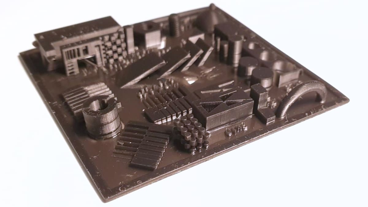
Michael’s Calibration Matrix is a combination of tests put together by the designer to take resin printer calibration to new heights. Inspired by Phrozen’s validation matrix and Tableflips’s Cones of Calibration, this remix combines them and adds more detail for testing resin printers. Included are exposure triangles, varying cones, checkerboards, depth elements, slits, and more.
Each element is crucial, whether for testing printability, resolution, or dimensional accuracy. For starters, the cones, cylinders, and slits let you examine the minimum width and height of openings, letting you fine-tune exposure settings and pigment quantities. Additionally, the Matrix incorporates free-standing exposure tests and flat overhang assessments to evaluate layer rigidity, a key factor in achieving robust and durable prints.
Furthermore, it has elements for shrinkage and resin cleaning assessment. For example, the three-layered stacked cylinders allow for shrinkage analysis and evaluation of how well resin can drain out of spaces. Moreover, the Matrix has an M3 thread and nut for leveling or thread-cutting evaluation. With a diverse range of components, the Calibration Matrix serves as a comprehensive test print for resin.
- Who designed it? Biolippi
- How printable/popular is it? This model has only two published makes and around 7,400 downloads but it’s one of the most comprehensive tests for resin printers. It’s received over 470 likes on Thingiverse.
- Where to find it? Thingiverse
For Precise Dimensions: Shrinkage & Exposure Calibration Piece
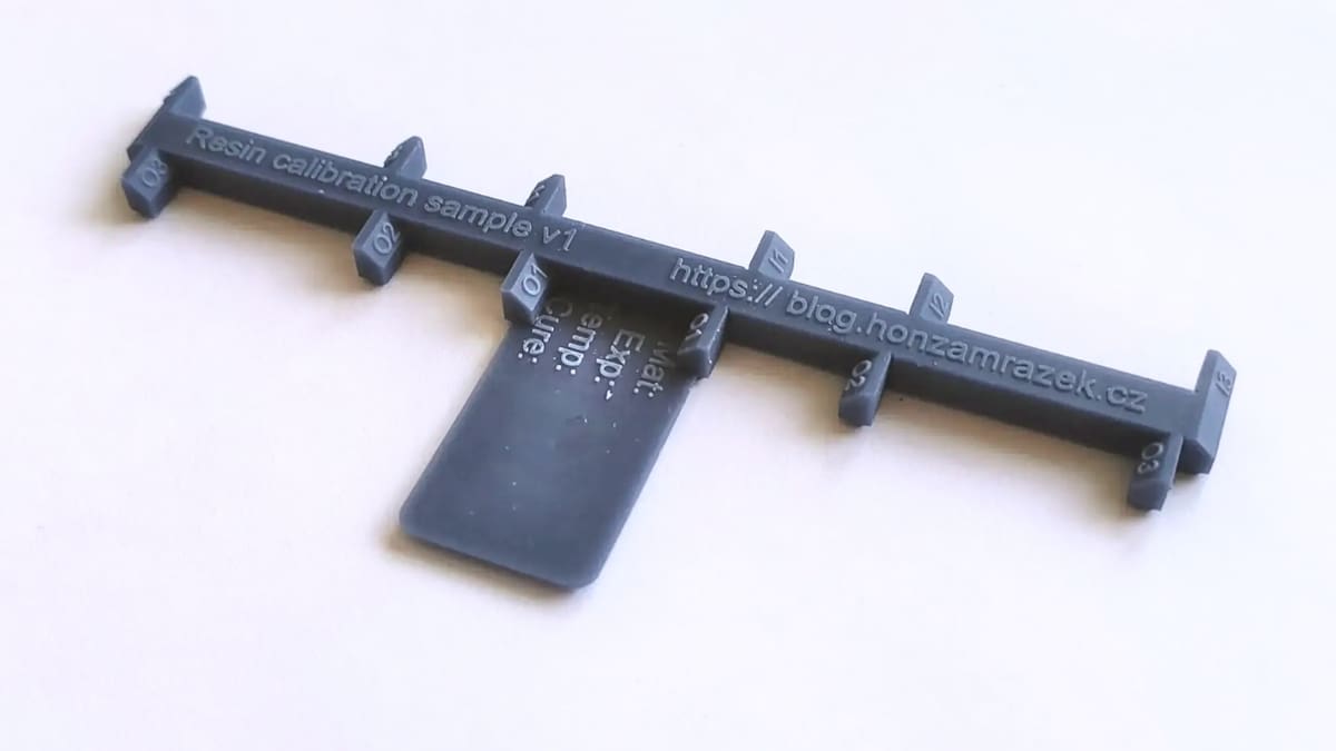
Want your resin prints to meet precise dimensions? The Shrinkage and Exposure Calibration Piece is designed to help you estimate and counteract resin shrinkage. Resin naturally shrinks by approximately 1-2% in total volume as it cures. This calibration piece provides a practical way to measure a particular material’s shrinkage accurately.
The suggestion from the designer is to print this using standard settings. It should be placed flat on the build plate and left to cure. Once completed, it becomes a useful test print for measuring the degree of shrinkage. Jan Mrázek created the resin test print, which comes in two variations: one for direct printing and another that can be used as a mold for crafting a silicone model.
This model is useful for anyone who wants to learn about resin shrinkage as well as exposure bleeding through a small test print and some calculations. Once you have measured the calibration piece, there’s no need to calculate the shrinkage manually. Simply use the companion calculator, which provides two essential values: “XY model scale for compensation” and “tolerance compensation”. With these figures, you can input the required adjustments into the slicer to counteract shrinkage and effectively achieve accurate resin prints.
- Who designed it? Yaqwsx
- How printable/popular is it? This model has 4 published makes and around 3,300 downloads.
- Where to find it? Printables
For Accuracy: Calibration Measurement
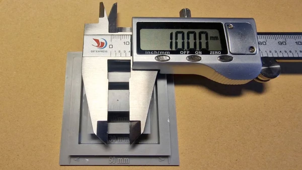
In the quest for accurate 3D prints, calibration plays a crucial role, and this calibration measurement print for resin is here to help you achieve exactly that. The key objective is to validate the printer’s accuracy by measuring five distinct lengths ranging from 10 to 50 mm. You’ll need a Vernier or a digital caliper, which will become your essential tool in this calibration journey.
This test print comes in two height variants. You can choose between the two depending on your preference for printing speed or ease of use. The first variant, the longer one, has a total vertical height of 17 mm, while the second, faster printing option stands at 7 mm. This height difference influences the ease of measurement, making the longer variant more accessible.
To obtain the measurements, you can use the external jaws of a caliper to measure 50 mm, 30 mm, and 10 mm with ease. For precise measurements of 20 mm and 40 mm, the internal jaws of the caliper should be used to ensure accuracy in each calibration measurement.
- Who designed it? DidaW
- How printable/popular is it? Although this model has over 1,700 downloads and 1 published make, the original print of this model looks good and is as useful for measuring calibration as can be.
- Where to find it? Printables, Thingiverse
Bonus: Fast and Cheap to Print
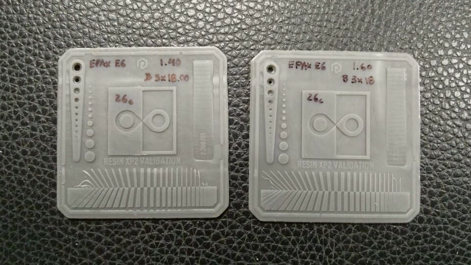
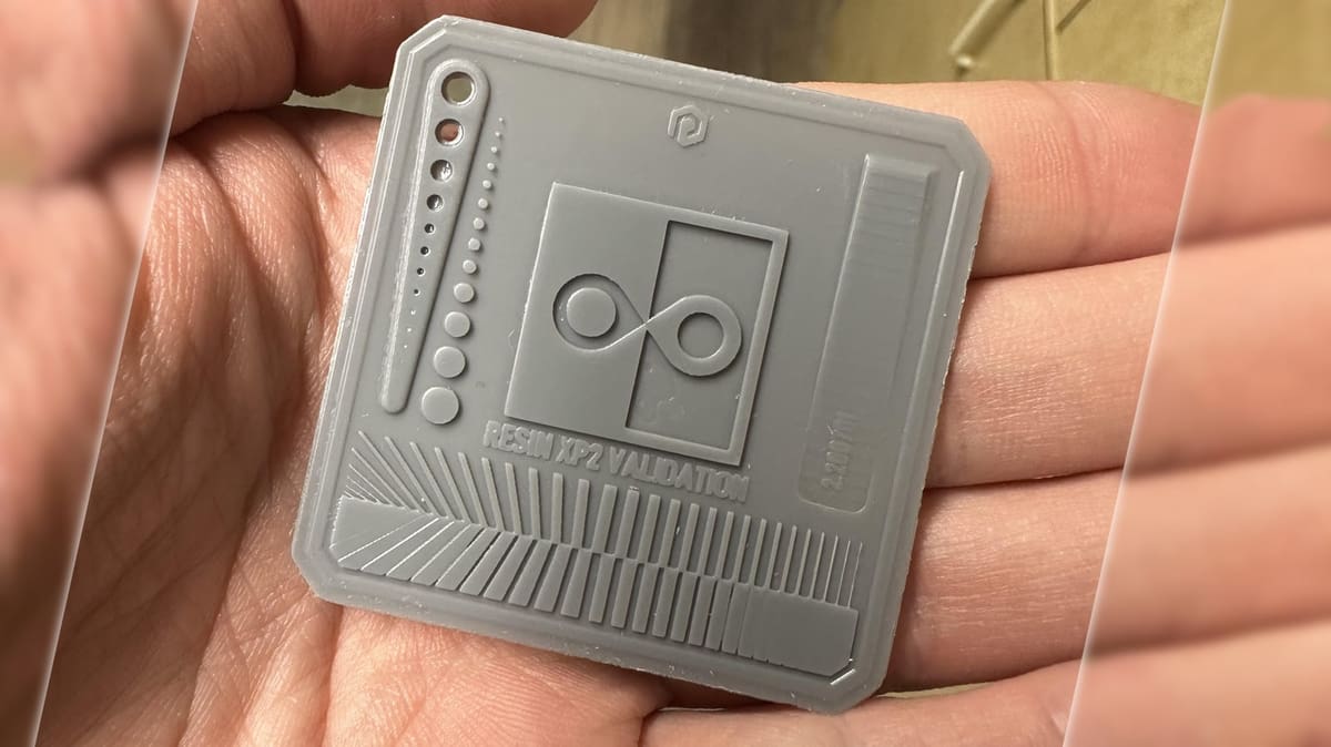
The Validation Matrix is the fastest test model to print on this list and uses the least amount of resin. It contains four different features, all of which are for testing exposure balance. To successfully print this model with accurate results, a bottom layer count of four is highly recommended by the designer. Its compact form factor and fast print times make the Matrix popular for YouTube videos and tutorials aimed at those new to resin printing.
In terms of the tests, there should be the same number of pins and holes on the left-hand side of the Matrix. In the center is a square with two teardrops that should barely meet in the middle of the square. The square itself should be 20 mm in length and width, with a 1-mm edge on the righthand side.
- Who designed it? Photonsters
- How printable/popular is it? The validation matrix has 16 makes on Printables and there are almost 189,000 views of Slice Print Roleplay’s YouTube tutorial.
- Where to find it? GitHub, Cults (shared by X3MSnake), Printables (shared by RedNightPrinting)
Bonus: Lattice Benchy 1
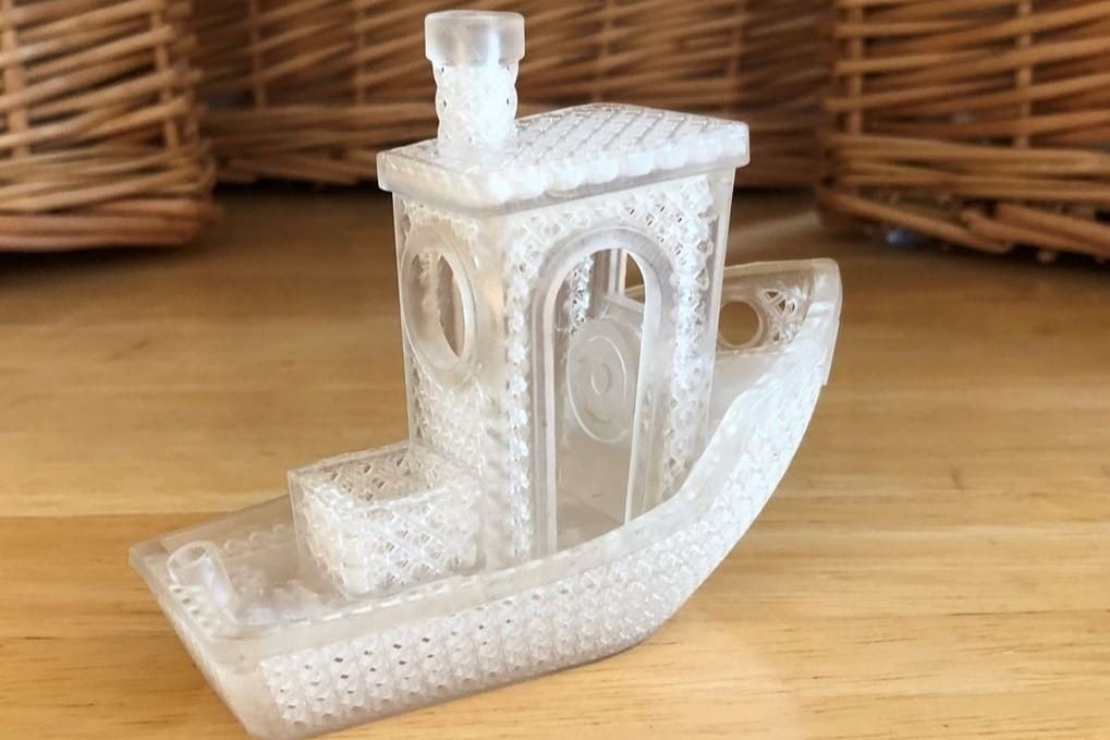
Okay, there is a Bency for resin printer calibration, but it really doesn’t have much to do with the FDM version. Here, we’re looking to test the limits of your printer’s resolution and display the intricate design elements that a resin printer can produce. For that, the Lattice Benchy 1, a remix of the renowned 3DBenchy test model, is an ideal test print. Its smooth curves, small holes, and complex features offer an excellent opportunity for testing and refining the resolution of resin printers.
By printing this model, you can examine the printer’s performance in multiple aspects. From surface quality to dimensional accuracy, the Lattice Benchy 1 also evaluates the printer’s precision and capability to produce intricate structures. Moreover, this test print showcases the entire printing system’s capabilities, including the printing material’s viscosity to the final result.
More than a beautiful little tug boat, the Lattice Benchy 1 offers a glimpse into resin printing precision. This print is 100 mm long and features lattice structures as small as 1 mm in diameter, showcasing the remarkable precision of resin printers.
- Who designed it? DaveMakesStuff
- How printable/popular is it? This model has 3 published makes, over 3,000 downloads, and has earned around 340 likes on Thingiverse – numbers that will surely keep on growing.
- Where to find it? Thingiverse
You May Also Like:
What Calibration Models Can’t Tell You
A successful calibration print is a useful baseline, but it doesn’t guarantee that every model will print correctly. Most test pieces isolate a handful of settings under controlled conditions, while failures on real projects can depend on where the model is placed, how it is supported, and the geometry of the sliced file.
Problems Elsewhere on the Build Plate
A small test printed in the center may not reveal weak areas of the light source, screen contamination, damaged release film, or a build plate that performs differently near its edges. This is particularly important on large-format printers.
To check the whole build area, place identical copies of a small test near the center and corners, or use a zoned build-plate calibration. If the same model produces noticeably different results in different positions, inspect the screen, optical system, release film, and plate leveling before adjusting exposure.
Model-Specific Supports and Geometry
A generic test can’t determine whether the supports and orientation of another model are suitable. Large cross-sections, thin support tips, heavy parts, and poorly positioned supports can all cause failures even when exposure is correctly calibrated. A small test may also succeed with motion settings that become unreliable when printing a larger or heavier object.
Before starting the final print, review the sliced layers and check that important areas are supported. Pay particular attention to sudden increases in cross-sectional area and sections that begin in mid-air.
Islands, Suction Cups, and Trapped Resin
Islands and suction cups depend on the geometry and orientation of the actual model, so they can’t be ruled out by printing an unrelated calibration piece. An island is an area that begins printing without being connected to the build plate or a previously supported section. A suction cup forms when a cavity traps resin or air without an adequate escape route, creating additional forces as the model separates from the release film.
Hollow models can also trap uncured resin, potentially causing cracks or leaks later. Use the slicer’s island and suction-cup detection tools where available, inspect the layer preview, and add suitably placed drainage and vent holes. Passing a calibration test does not make an improperly hollowed or unsupported model safe to print.
Temperature, Motion, and Mechanical Problems
Test models don’t always reproduce the forces generated by a full build plate or a model with large solid layers. Failures may still result from insufficient lift distance, excessive lift speed, inadequate rest time, a worn or incorrectly tensioned release film, loose Z-axis components, or vibration.
Resin condition matters too. Cold, poorly mixed, or unusually viscous resin can behave differently from the resin used during calibration. Keep the printing environment consistent, mix the resin thoroughly, and recalibrate after changing resin, layer height, release film, or other important parts of the setup.
Anti-Aliasing
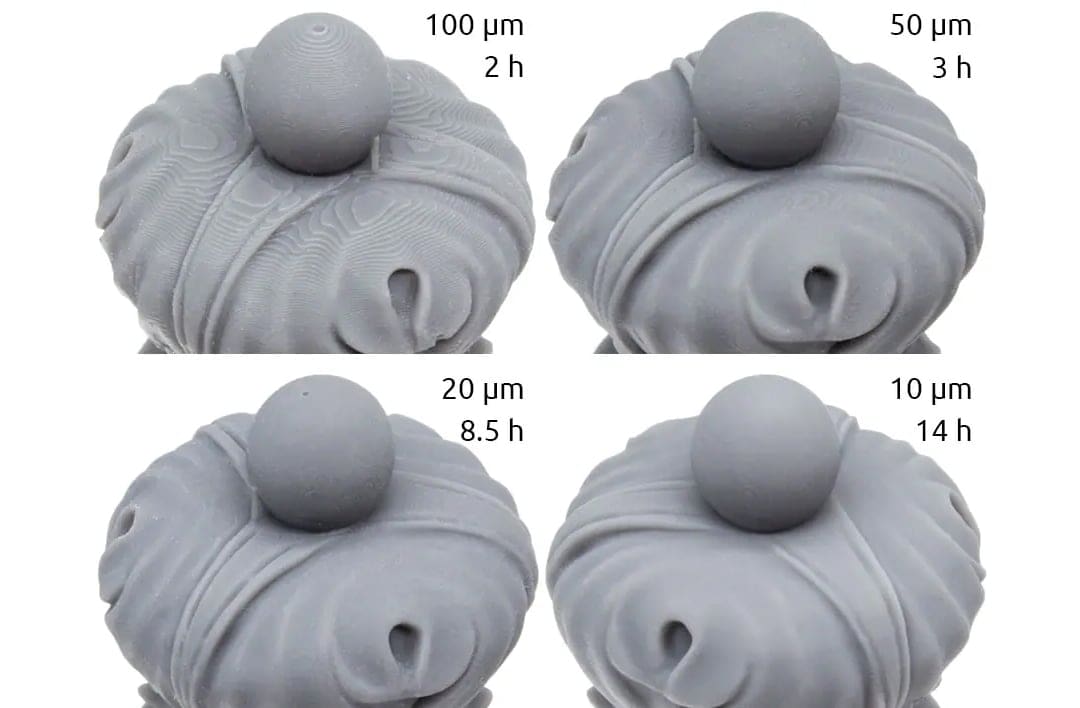
Anti-aliasing should be evaluated separately from exposure because it changes the edges used to judge fine details and dimensional accuracy. Strong smoothing or image blur can make surfaces appear cleaner while softening corners, closing small gaps, or removing fine textures.
Calibrate exposure with anti-aliasing disabled first. Once the exposure setting is saved, print matching samples with different anti-aliasing levels and compare their curved surfaces, lettering, edges, and smallest details. The best setting will depend on whether the priority is a smoother finish or maximum sharpness.
Ultimately, a calibration model tells you how a particular printer, resin, and profile handle its included features. Before committing to a long or expensive print, inspect the actual sliced file and, where practical, print a representative section or smaller real-world model using the same orientation, supports, hollowing, and settings.
You May Also Like:

License: The text of "Fix Your Fails: The 10 Best Models to Calibrate Your Resin 3D Printer" by All3DP is licensed under a Creative Commons Attribution 4.0 International License.