3D Printing Tolerances: How to Test & Improve Them

Can you trust the dimensional accuracy of your 3D prints? Find out how to easily test and improve your tolerances.
Simply put, tolerances describe how much deviation from a particular value is expected or acceptable. This can be in any manufacturing context that uses precise measurements, including additive manufacturing.
Whether you’ve been 3D printing for a while or you’re just getting started and looking at filament specs, you’ll have come across a type of tolerance. For example, Prusament PLA is listed to have a diameter of 1.75 mm ±0.02 mm, which means that any diameter value between 1.73 mm and 1.77 mm is possible. In other words, “±0.02 mm” indicates that deviations up to 0.02 mm wider or narrower in the filament are tolerable.
3D printing machines also have certain tolerances. This means that prints may slightly deviate from the actual dimensions. A tighter (closer to zero) tolerance indicates consistently higher dimensional accuracy.
In this article, we’ll dig a little deeper into tolerances and look at types of fits, what can cause FDM inaccuracies, how to test tolerances, as well as solutions that range from the first stages of designing a part to post-processing models. Buckle up!
Why Tolerances Matter
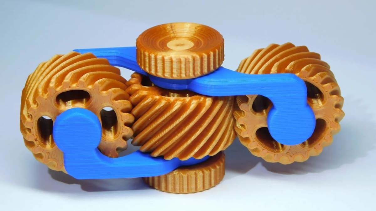
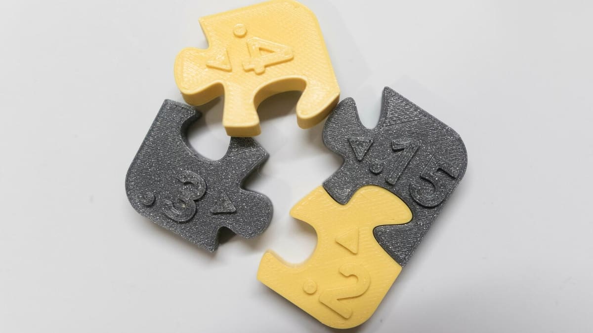
3D printing tolerances are particularly important when you make parts that need to fit closely together. For example, a print with mechanical assembly will require tighter tolerances than a decorative box or simple container. With fused deposition modeling (FDM) 3D printing, you need to watch out because tolerances tend to be somewhat haphazard. For example, features such as holes usually need to be slightly oversized in order to match the modeled diameter.
Let’s make one important clarification: In this article, we will be referring to tolerances – which should be understood as ranges, for example, 1.73 to 1.77 mm for FDM filament – as well as clearances – which are values describing the spaces between parts.
When designing parts with small clearances, you should be aware of your printer’s tolerances and if you can achieve the required accuracy. Parts should be created with enough space between them to account for potential dimensional deviations. Small measurement deviations can cause the clearance to become fused.
A poor understanding of your 3D printer’s tolerances might result in parts that fit poorly, or your support structures might be completely stuck to your prints. Also, it’s important to know that no two printers will have the same tolerance, even if they’re the same model. Make sure you find what works for your machine, and don’t rely on someone else’s tolerance values.
Before diving into how to test and improve your printer’s limits, let’s take a closer look at types of fits.
Types of Fits
In most applications, a joint between two parts fulfills a particular function. Let’s illustrate this with an example.
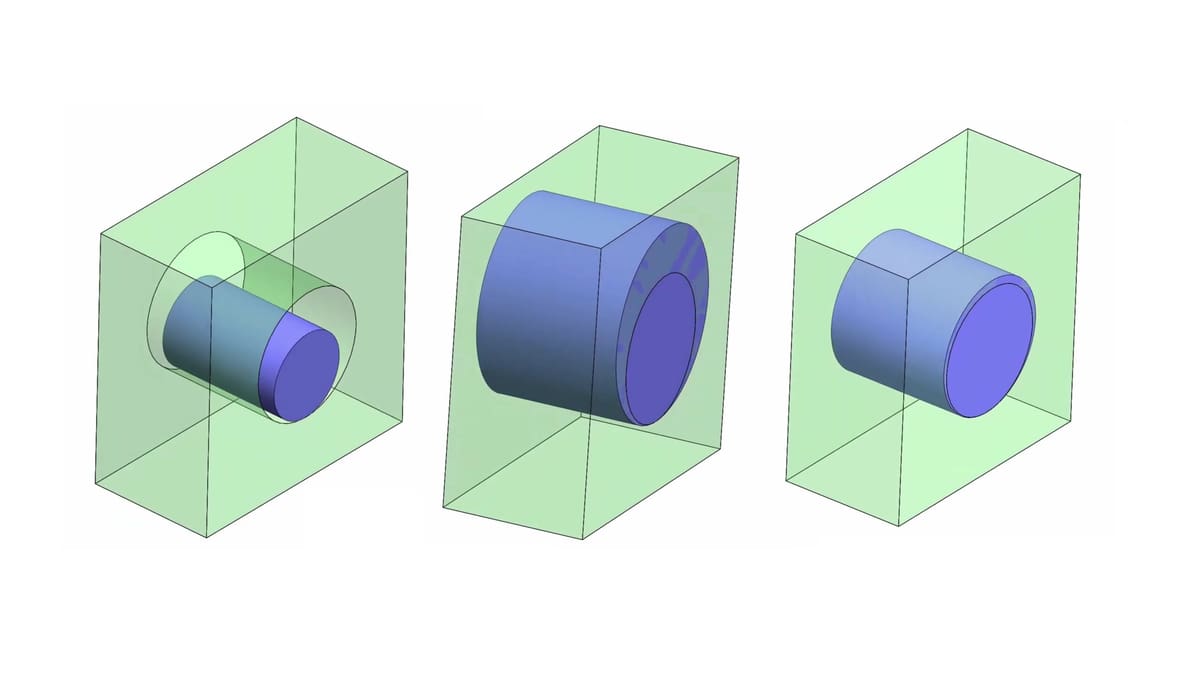
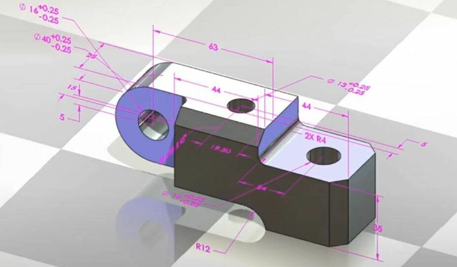
Consider a circular shaft designed with a nominal diameter of 50 mm, which should fit into a round hole with a nominal diameter of 50 mm. Practically, there are three options for how these two parts could fit together:
- Clearance fit: The shaft diameter is significantly narrower than the hole diameter, say 49.8 and 50.2 mm, respectively. In this case, the shaft will easily slide in and out of the hole and rotate inside of it.
- Interference fit: The shaft’s diameter is the same as or slightly wider than the hole’s, say 50.2 and 49.8 mm, respectively. The shaft won’t enter the hole without a lot of force. Once entered, it will probably not get out without breaking the parts. This type of fit is used extensively when high concentricity and mutual motion are required (like attaching a shaft to a bearing).
- Transition fit: The shaft diameter is just slightly smaller than that of the hole, say 49.9 and 50.0 mm, respectively. The shaft will fit into the hole with minimal pressure and maintain relative concentricity. Alternatively, the shaft diameter may be just slightly larger than that of the hole and will require slightly more pressure (but not as much as for an interference fit).
In reality, each fit type spans a spectrum of allowable combinations. The dimensions given above are just examples. To properly select a fit and design accordingly, there are several international standards (such as ISO tolerance), but we won’t go into that in this article.
Nevertheless, the type of fit needs to be determined before setting the tolerances. If properly set, two interacting parts will still function as intended regardless of how close they are to the positive or negative range limits.
Causes of FDM Inaccuracies
Besides design errors (which are endemic to any manufacturing process), there are a few key causes of inaccuracies inherent to 3D printing, and in particular to FDM machines. Being aware of these factors will help you improve your tolerances where necessary.
Software Errors
When a digital model is converted to STL, some details are inevitably lost. For example, round objects are faceted and converted to straight surfaces and vertices. However, the higher the conversion resolution, the less the dimensional error caused in the part.
Slicers might introduce their own errors, depending on their specific algorithms and settings. How slicers alter the vertices of an STL file will greatly affect how the G-code will look and therefore how the printer will behave.

Machine Inaccuracies
There are several ways that a 3D printer itself can cause inaccuracies in a printed part. Stepper motors have a finite resolution of mobility, so the accuracy of a movement path is only as accurate as the maximal resolution of the motors. In addition, typical motors for FDM 3D printing do not have a position control loop, so small errors in position can accumulate over long print jobs. Most motor drivers also have a thermal protection feature that stops them from working if they overheat, which may cause the motor to skip steps. Stepper motor E-steps are also a crucial factor that may cause dimensional inaccuracies if not calibrated properly.
If the axes of the printer are not adequately orthogonal to one another, structural inaccuracies will appear. Imagine trying to draw a rectangle with an axis that’s not perpendicular – you will end up with a parallelogram. Then, every time a motion axis changes direction, there’s a small amount of backlash. The less tension in the belt system, the more prominent the backlash. Belts also introduce other issues over time, such as creep and elongation, which not only reduce tension but may also cause slips and missing steps.
As the printer prints a line of filament, it’s expected to create a uniform width. However, the beginning of a print line can be thinner and widen by the end of the line as the nozzle pressure increases. This is exaggerated when cornering. General over-extrusion of filament will also cause a wider print line, which may cause the overall dimension to become too big, with the opposite effect for under-extrusion, and the quality and condition of the filament can lead to further extrusion issues.
Finally, improper initial Z height can cause elephant’s foot, when the first layer is spread wider than the subsequent layers due to the weight of the print.
Instead of waiting around to see if your prints work or not, you can avoid issues by testing for both tolerances and clearances, which we’ll look at next.
Testing
For Tolerances
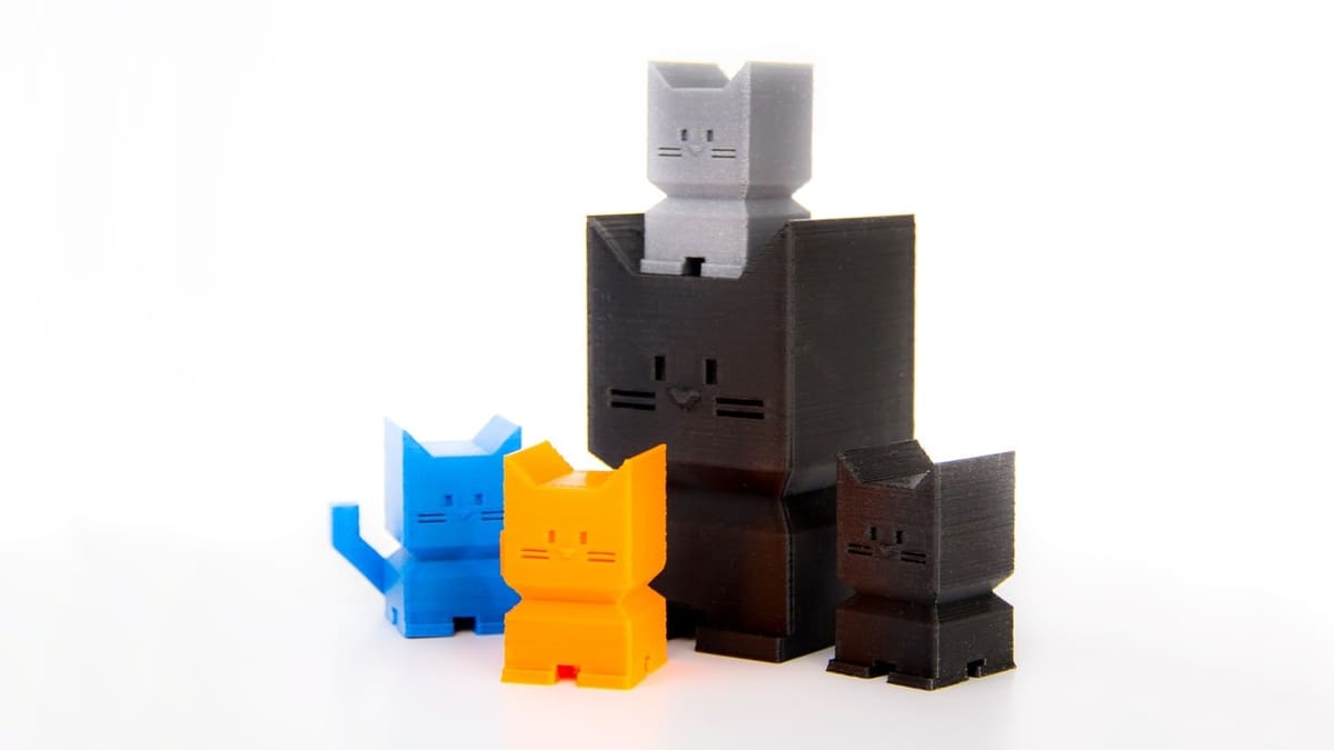
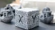
To test your 3D printer’s tolerances, start by properly calibrating your printer and its extruder. A helpful tool in this endeavor is a calibration cube. When you’re ready, print out three to five calibration cubes, or try the calibration cat model by Dezign if you want something a bit more fun.
Using calipers, measure each of the prints in the same place. Note the model’s orientation (indicated by the large letters on the calibration cube). Record at least three measurements for each of the three directions (X, Y, and Z).
For each direction, subtract the smallest measurement from the largest measurement. This number is a good starting point for designing clearances, or the space required between printed interfaces. The tolerance of your printer will be ± half of the clearance value.
Example: You might get 20.1 mm, 20.0 mm, and 19.9 mm for the calibration cube Y dimensions. Your clearance will be 20.1-19.9, which is 0.2 mm, meaning your printer’s tolerance is ±0.1 mm.
It’s worth noting that whatever value you obtain isn’t necessarily a “permanent” one. It will very much depend on your printer’s current state as well as whatever material you’re using.
For Clearances
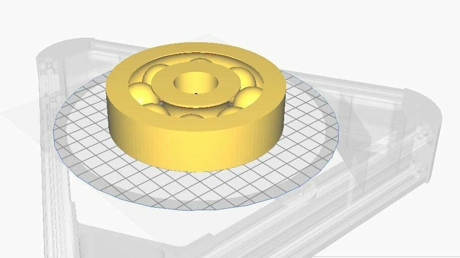
Alternatively, you can test directly for clearances. This is helpful if you’re only interested in fitting 3D printed parts with other 3D printed parts.
Angus Deveson from the YouTube channel Maker’s Muse has created a couple of helpful clearance tests, one for free and one for $2. Just follow his guides. There are also several other great clearance tests, such as this one by zapta on Thingiverse and this one (inspired by Maker’s Muse’s tests) from 3DMakerNoob on Printables.
With this tool, you can figure out how low you can set the clearances in your designs.
And if you’ve found that the tolerances or clearances are all over the place and you want to improve your design or your printer’s performance, there are still a few things you can do.
Solutions
Design
Once you’ve understood the potential reasons for inaccuracies in your prints, you can take active precautions to eliminate them as much as possible. Practically, you can’t expect a common FDM printer to nail a dimension to within 100 microns, or 0.1 mm (conservatively). This means that all of your dimensions should be designed under the assumption that they may come out larger or smaller by this value.
For mating parts, you’ll have to design them so that even with the uncontrolled error in the dimensions, they will still work together as designed. In almost all cases, this means that if you have two parts that should fit together, you’ll need to design one part smaller than the other. For a standard 0.4 mm nozzle, here are some general rules of thumb for fits based on a hole and shaft join. Keep in mind that you’ll have to experiment and learn the actual values for your printer.
- Clearance fit: A difference of 0.5 mm and above between the diameter of the hole and the diameter of the shaft. This results in a theoretical gap of at least 0.25 mm between the shaft and the hole.
- Interference fit: A difference of around 0.1 mm or less between the diameter of the hole and the diameter of the shaft. This results in a theoretical gap of 0.05 mm or smaller between the two parts.
- Transition fit: A difference of 0.15-0.4 mm between the diameter of the hole and the diameter of the shaft. This results in a theoretical gap of 0.08-0.2 mm between the shaft and the hole.
Since these rules relate to the difference between the parts, they can also be used for non-cylindrical parts. When considering non-cylindrical mating parts, like a square hole and a corresponding square protrusion, the above-mentioned rules may apply to the difference between the closest planes of the mate. For example, to get a clearance fit for a 30 mm square rod, design the hole so that a gap of 0.25 mm is maintained (i.e. a 30.5 mm square).
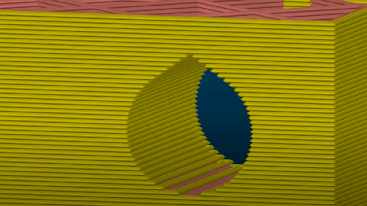
Another key guideline is to consider the orientation of the part to achieve maximum quality. Holes are best printed horizontally (parallel to the XY-plane of the printer). If you must print a vertical hole, use the teardrop technique, in which the upper portion of the hole is designed in a pointed shape rather than completely round. This eliminates any inaccuracies caused by the overhanging of the filament when closing the upper part of the hole.
In addition, because of the layered nature of FDM 3D printing, vertical features are usually less accurate as they can only be as fine as the layer height. Horizontal (XY) features tend to be more accurate because they’re only limited by the stepper motors’ resolution and the belt, as explained in previous sections.
Software
Several software solutions may help increase the accuracy of your prints. When slicing a part to print with maximum accuracy, you should generally use slower kinematics (speed, acceleration, and jerk), smaller layer heights, and active part cooling. We recommend a print speed of less than 60 mm/s, acceleration of less than 3,000 mm/s2, and jerk of less than 15 mm/s for most desktop printers.
In the slicer settings, there are some unique features that can help improve dimensional accuracy. The following examples are for Cura, but most slicers have similar features.
- Outer before inner walls: By printing the outer walls first, you can theoretically improve the dimensional accuracy by not being bumped by the internal walls or infill.
- Coasting: This feature causes the printer to stop extruding toward the end of a move and instead rely on the residual pressure in the nozzle to print the rest of the filament for the move.
- Horizontal expansion: This feature increases or decreases a part’s dimensions by a specific percentage. Ideally, this can help fine-tune the dimensions of the print, but it’s really only useful if the entire print is too small or too big. If the overall dimensions of the print are acceptable and only holes need to be tweaked, for example, a different method should be used, such as the “Hole horizontal expansion” feature.
- Dial in your print settings: Issues such as having the heated bed too hot can cause dimensional accuracy problems, like the previously mentioned elephant’s foot. Likewise, if the extruder is too hot for a given filament, it can cause stringing and blobs, which will also throw off your clearances.
After slicing, the linear advance feature in Marlin (and some other firmware) adjusts the flow of the filament according to predicted print moves. This feature anticipates the variation in nozzle pressure that can lead to inconsistent extrusion and adjusts it accordingly. It converts an inconsistent line width into a more uniform line, which improves the dimensional accuracy of the print. Linear advance has a similar effect to coasting settings in your slicer but is generally easier to tune.
Machine
Perhaps the most important way to achieve maximum print accuracy and stay within tolerance is by calibrating the actual printer. A poorly calibrated printer will result in parts that aren’t straight, don’t have the right dimensions, and don’t fit each other. On top of that, always remember that no hobby-grade desktop 3D printers are perfectly and completely calibrated from the start, even if they come pre-assembled; they will require additional calibration over time as a routine maintenance operation. While professional-level machines might somewhat compensate for this, they will still benefit from regular maintenance and calibration.
Since poor calibration can cancel out all of your efforts in designing and slicing to meet tolerance, the importance of machine calibration cannot be underestimated. The most important elements to calibrate are the extruder and E-steps, and it’s always vital to start with a good first layer. You might like to use a test model to check that everything is in order before starting a print.
It’s also important to select good-quality nozzles and filament, as the dimensional accuracy of your part heavily relies on the assumption that the extruded filament is actually the width it should be. Cheap filaments usually have poor tolerances, which can cause extrusion irregularities and translate to irregular surfaces on your prints. The best filaments have low tolerances, fewer impurities, and proper storage. Significant deviations in filament diameter or poorly machined nozzles will have an immediate impact on the tolerances of your prints.
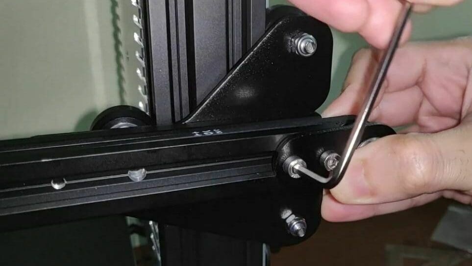
As a final note, deteriorating components will also make your printer less precise. Ensure that your printer’s belts are taut and that there’s minimal wear on the rods or bearings. If not, tighten or replace the parts. Consult your printer’s manufacturer on how best to approach this task.
Post-Processing
Even after all the calibration, proper design, and special slicing configurations, parts may still be out of tolerance. In that case, they’ll need to be brought into line with post-processing.
There’s no shame in accepting the need to post-process a part. Even with extremely accurate CNC machining centers that cost hundreds of thousands of dollars, it’s sometimes necessary to perform some post-processing on parts to make them fit and meet specifications.
It’s important to note that post-processing usually refers to subtractive methods, so it’s more relevant for parts that are oversized rather than undersized. Here are a few key tips to bring your parts down to the designed dimensions:
- Sand and file parts to remove elephant’s foot, supports leftovers, and other printing artifacts.
- Keep measuring the parts as you post-process them until you reach the desired dimensions.
- Drill or ream any 3D printed hole.
- Try to avoid supports if possible. It’s much easier to re-drill a hole than to try to pry out small supports with a pair of pliers.
Finally, at some point, we have to acknowledge that certain geometric dimensioning and tolerance (GD&T) requirements can’t be easily done at a DIY level. For example, testing and correcting the runout of a 3D printed shaft is beyond what most setups can achieve. But hopefully, following the guidelines presented in this article will save you some unnecessary post-processing and repeat prints!

License: The text of "3D Printing Tolerances: How to Test & Improve Them" by All3DP is licensed under a Creative Commons Attribution 4.0 International License.