Make Your Printer Z Wobble Free & Banish Z Banding From Your Prints

Regularly spaced bulges around a print's sides could be Z banding, and Z wobble might be the underlying problem. Learn how to diagnose and fix it!
Even with a good slicer profile and decent filament, your prints may still come out with those annoying horizontal lines. These repeating lines, especially on vertical walls are often a sign of Z banding, caused by mechanical imperfections or motion errors in the Z-axis. But don’t worry! The good news is, this issue is solvable.
Z banding is one of those classic FDM printing problems that seems to plague you when you’re just getting comfortable with your settings. You tweak the temperature, level the bed, and suddenly the sides of your print look wavy and uneven. In this article, we’ll help you to understand why Z banding occurs as well as how to fix it.
Let’s get started!

Understanding the Problem
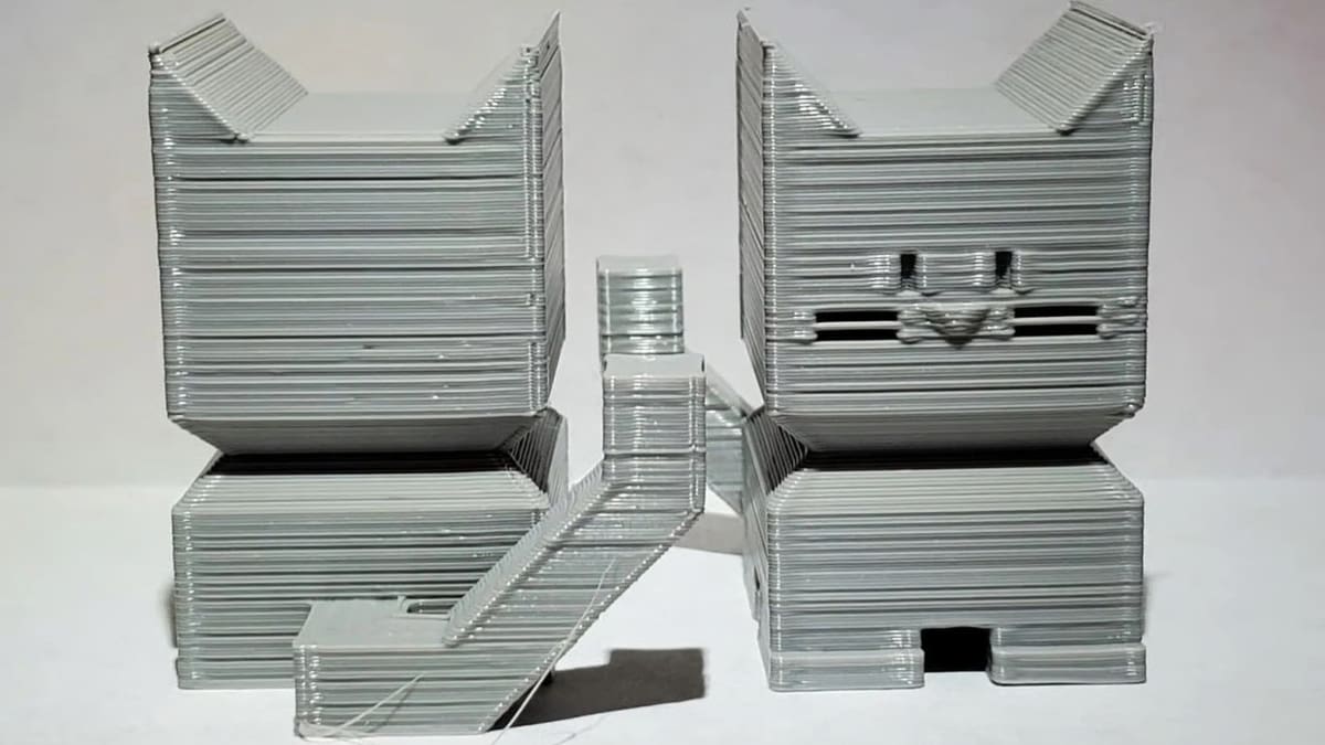
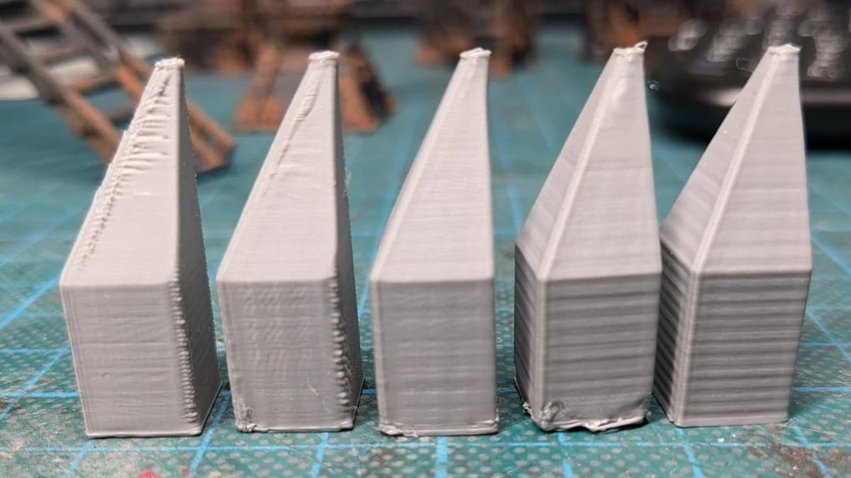
Z banding is a surface defect that shows up as horizontal lines or ripples along the vertical walls of a 3D print. These lines are not part of your model; they’re artifacts caused by inconsistencies in the printer’s movement along the Z-axis.
In a clean, well printed part, vertical surfaces should be smooth, even, and uniform. With Z banding, that surface starts to look wavy, ribbed, or like it has subtle steps running across it.
Z wobble, on the other hand, is usually a mechanical issue where the Z-axis doesn’t move in a perfectly straight line. Instead, it wobbles slightly as it rises, usually due to a bent lead screw, a misaligned coupler, or other causes.
This wobble causes the nozzle to shift side-to-side by tiny random amounts with each layer. As a result, the layers don’t stack perfectly, and you get repeating horizontal lines on the surface of your print – in other words, Z banding.
So, simply put:
- Z banding is the result. It’s what you see on the print.
- Z wobble is the cause. It’s a mechanical problem with the printer that introduces unwanted movement along the Z-axis that affects the print.
Why You Should Fix It?
You might think Z banding is just a minor visual issue, but it’s more than that. If left unfixed, it can affect both how your print looks and how well it performs.
In terms of functionality, Z banding can weaken your print. When the layers don’t align perfectly, the part may be less strong or not fit with other parts. This matters a lot if you’re printing mechanical parts, joints, or anything that needs precision.
Aesthetically speaking, Z banding makes your print look rough or unfinished. The surface won’t be smooth, and details will get distorted. If you’re printing for a client or even for yourself, a clean finish matters.
Most of the time, Z banding is caused by small mechanical issues that are easy to fix: a coupler that’s misaligned, a lead screw that’s slightly bent, or a loose mount. Those are quick and cheap to fix.
Root Causes
While Z banding is usually the result of problems with how the printer moves along its Z-axis, it isn’t always caused by mechanical wobble. Even if the motion is mechanically fine, extrusion inconsistencies, temperature control problems, slicer settings, or even environmental factors can sometimes create visual defects that look just like Z banding.
Below, we break down all the major causes that can lead to Z banding or similar looking surface artifacts. We’ll group them into four categories to make it easier to diagnose and fix:
- Mechanical
- Filament and Extrusion
- Firmware and Slicer Settings
- Environmental
Mechanical
This is the most common cause of Z banding and usually the first place to check. If your Z-axis doesn’t move in a straight line, you’ll see it in your prints.
Bent or Misaligned Z-Axis Lead Screw
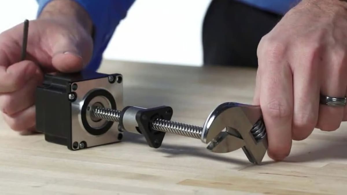
The lead screw – the long threaded rod that moves the gantry up and down – needs to be perfectly straight and well aligned. But sometimes, it becomes slightly bent.
Why is this a problem? As the screw turns, any bend causes it to “wobble” in a circular path. That motion gets passed to the X-axis gantry or bed, then causes the layers to shift a little with every complete turn.
The Fix
Honestly, trying to straighten the lead screw isn’t worth the trouble. The easiest and most reliable fix is to replace it with a new one.
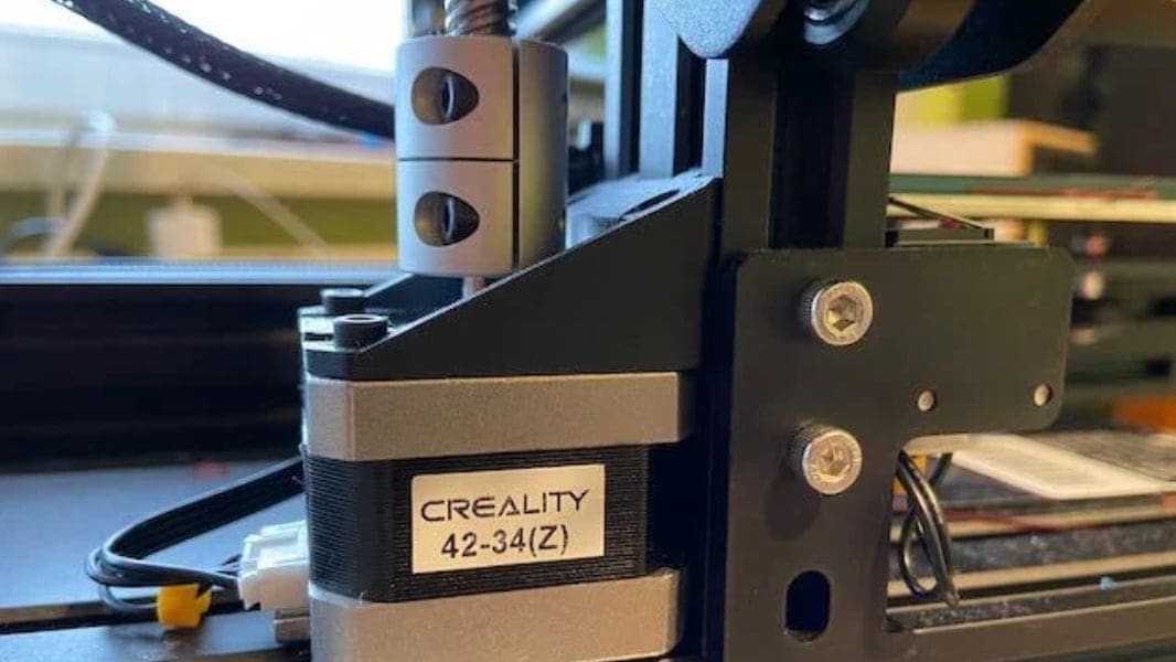
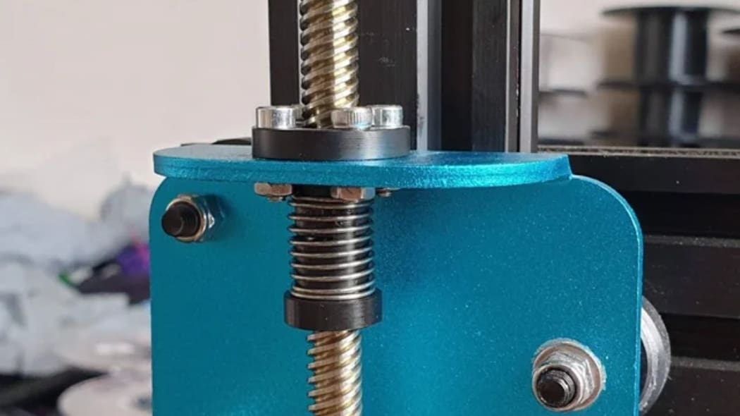
Loose, Misaligned, or Crooked Coupler
The coupler is the small part that connects your Z-axis stepper motor to the lead screw. It’s usually made of aluminum and comes in two main types: rigid and flexible. Flexible couplers are designed to absorb tiny misalignments or vibrations between the motor and the screw.
However, if the coupler is crooked, not sitting flat, or the set screws aren’t tight enough, it can actually introduce wobble instead of preventing it. When that happens, the lead screw won’t spin straight. Each time it turns, it will wobble. This creates visible Z banding in your prints as the layers build up.
The Fix
Turn off your printer and take a close look at your coupler. Make sure that both the motor shaft and the lead screw are inserted straight into the coupler and that the coupler sits flat on both ends.
The set screws should be tightened well. One screw should press against the flat side of the motor shaft (if available), and the lead screw should also be secure without any gaps or angles.
Gently rotate the coupler by hand and watch the lead screw. If it moves in a clean circle without wobble, you’re good. If it shifts side to side or the coupler jumps slightly, try loosening the screws, repositioning them, and tightening them again.
If your current coupler is too soft or poorly made, replace it with a good one. In most cases, just correcting the alignment and securing it properly is enough.
Z Nut & Mounting Issues
The Z nut is what rides up and down the lead screw. It’s attached to the gantry (or bed) and has a big impact on how smoothly your Z-axis moves.
If the nut is mounted too tight or at a slight angle, it will force the lead screw to bend as it turns. That tiny bend creates wobble and leads to Z banding. On the other hand, if the nut is too loose or the bracket isn’t secure, the gantry will shift or rock during printing. This will cause the layers to be misaligned, especially when the printer changes direction up and down.
The Fix
Check that the Z nut is straight and flat against the mount. Tighten it enough to hold it in place but not so much that it forces the screw out of alignment.
Z-Axis Stepper Motor Problems
As you know, the Z motor is what turns the lead screw and moves the printer up and down. If the motor is loose on the frame or mounted at a slight angle, it can tilt the lead screw and cause it to wobble.
Also, if the motor shaft itself is slightly bent, the whole screw will rotate in a wobbly circle instead of spinning around a straight line.
The Fix
Make sure the motor is well screwed to the frame and sitting flat. Try to rotate the screw by hand and see if the motor shaft wobbles. If it does, you might need to replace the motor with a new one.
Filament & Extrusion
If your printer is moving just fine, but you’re still getting these weird horizontal lines, the problem might be how the filament is being extruded. Small changes in how plastic comes out of the nozzle can create patterns that look like Z banding. Let’s explore the common scenarios.
Inconsistent Extrusion or Flow
If the extruder isn’t pushing out filament at a steady rate, you’ll get uneven layers. One layer might come out thin – in other words, under-extruded – and the next might come out thick to compensate, which creates a visible pattern that looks like Z banding.
Common reasons for inconsistent extrusion include the following:
- Partial clogs in the nozzle
- Dust or debris inside the hot end
- Filament slipping on the drive gear
- Weak extruder motor or low stepper current
A partially clogged nozzle can behave unpredictably. It may restrict flow one moment, then suddenly clear and overshoot. This on-off pattern can repeat over and over, showing up as horizontal lines in your print.
The Fix
Start by cleaning the nozzle. You can try a cold pull or use a cleaning filament. Then, check the filament path, ensuring that it’s smooth and that there’s no dust or worn-out PTFE tubing. Lastly, make sure the extruder is gripping the filament well and not slipping.
You’ll also want to make sure you’re using high-quality filament. A good filament has a tolerance of ±0.02 mm, while low-quality filament often varies in diameter. For example, one section might be 1.70 mm and another 1.79 mm. 3D printers assume a constant diameter, so tiny variations like this can affect how much plastic is extruded each layer.
Incorrect Printing Temperature
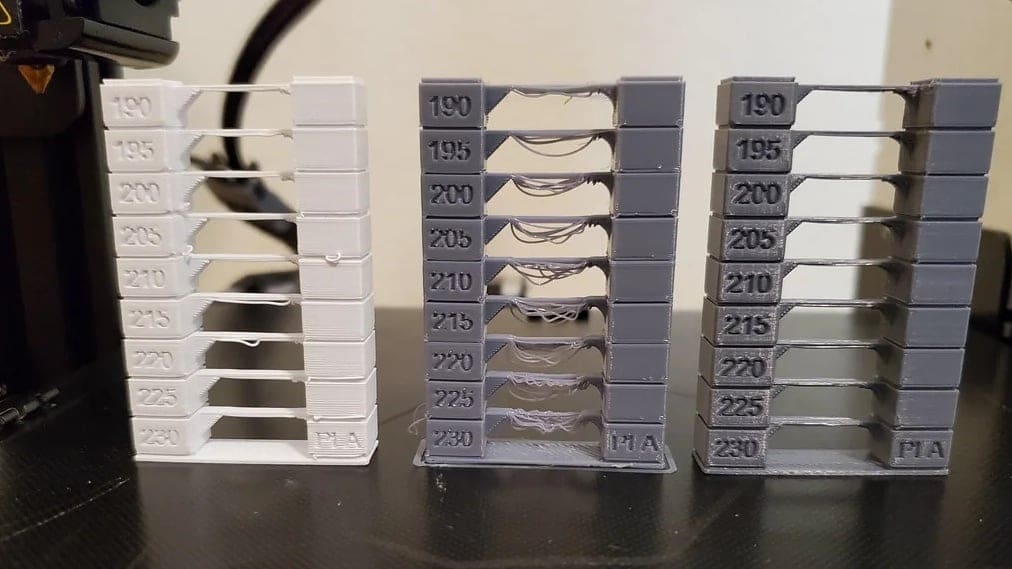
The nozzle temperature affects how the filament melts and flows. If the nozzle is too cold, the plastic might not melt fast enough – which can cause small gaps between layers. You might see lines that look like banding.
If the nozzle is too hot, the filament can come out too fast or too soft. That can create blobs or make the surface look rough. Even if the temperature looks okay, it might still go up and down during printing. These small changes can mess with the flow and cause visible lines on the print.
The Fix
Use the right temperature for your filament. You can check the label on the spool for the best range or print a temperature test.
Also, make sure your printer keeps the temperature steady. If your printer allows it, run PID tuning. That helps the nozzle hold the right temperature more accurately (we’ll explain that in more detail below).
Uneven Cooling & Shrinkage
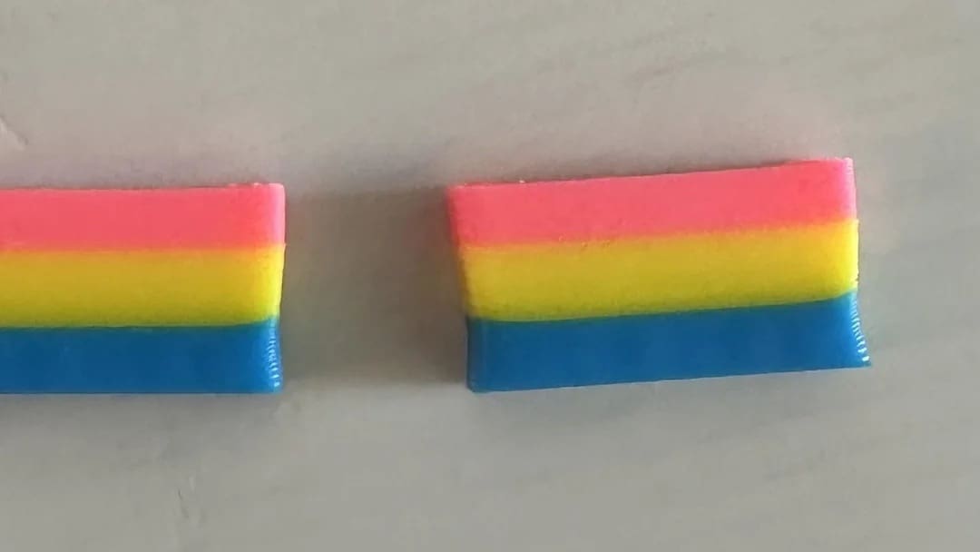
When the filament cools down after coming out of the nozzle, it shrinks a little. Some materials like PLA are stable, but others like ABS shrink more. If some parts of your print cool faster than others, you can get small distortions or lines that look like Z banding.
This can happen if your printer is near a window, fan, or air conditioner. A draft can cool one side more than the other and make things worse. It’s also more noticeable on taller prints or when the room temperature changes while printing.
The Fix
Try to keep the room temperature stable while the printer is in operation. Don’t place your printer near drafts or direct airflow.
If you’re using a material like ABS, it helps to have an enclosure. That keeps the print warm and prevents uneven cooling.
Firmware & Slicer
Sometimes, your hardware is perfectly fine, but your printer still produces strange banding. In that case, the problem might come from the firmware or the slicer settings. These are less obvious but still very common.
Temperature Control Cycles
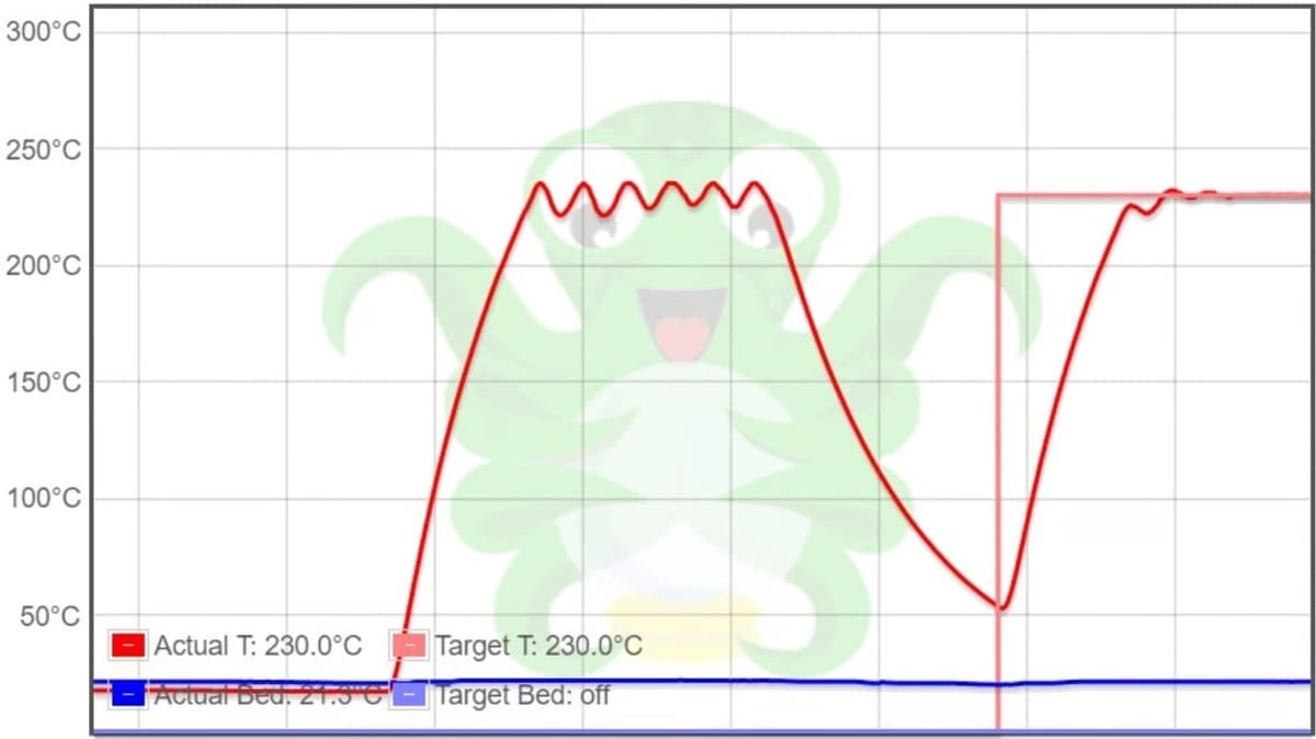
Both the hot end and heated bed need to hold a steady temperature during printing. Some older printers or budget models use something called “bang bang” heating control, especially in the heated bed. It works with the same concept as an old thermostat: When the temperature drops, the heater turns on full power. When it reaches the set point, it turns off completely. This on-off cycle keeps repeating to maintain the set point.
The problem is, every time the temperature rises and falls, it can cause small expansions and contractions. That tiny movement might not be obvious, but over time, it can show up as regular bands or surface artifacts in your print, especially if the cycle lines up with your layer time.
Newer or better printers use PID control instead. PID stands for Proportional, Integral, Derivative. It sounds complex, but what it does is simple. It keeps the temperature stable by adjusting the heater smoothly instead of jumping between on and off. For a deeper dive, check out our article on PID tuning.
The Fix
If your printer supports PID control (most modern ones do), you can calibrate it. PID tuning tells the firmware how your specific printer heats up and cools down. It runs a short test and adjusts the values to match your machine in your real-time environment.
Once PID is tuned, the hot end and bed will be more stable. Your printer should then be able hold temperature more smoothly, and those repeating bands caused by heat cycles should disappear.
Adaptive Layer Height
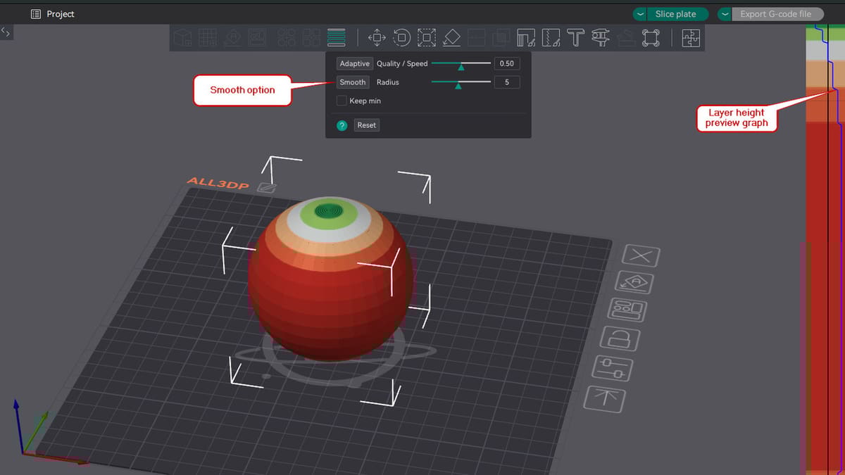
Adaptive Layer Height is a slicer feature included in many slicers like the popular Orca Slicer. It applies a variable layer height through your model in a smart, automatic way instead of a uniform layer height. In areas without fine details, the feature uses a larger layer height, and where detail is necessary, a smaller layer height is used. As you can image, this saves on print time.
Sometimes, however, a visible ripple or banding effect is created if the layer height changes too suddenly between regions.
The Fix
To avoid these artifacts, the transitions need to be smoother throughout your print. Orca Slicer has a straightforward option called “Smooth” within this feature menu. It helps in making these transitions smoother; every time you click this option, it gets smoother and smoother.
Alternatively, you can also take full manual control using the layer height preview graph on the right side of the screen. Hovering over the panel will highlight certain areas of the models, and you can use left or right clicks on your mouse to adjust the layer height.
Layer Height & Microstepping
Your printer’s Z motor moves the nozzle up in small steps. Each of these steps is translated to a fixed distance, depending on the type of lead screw your printer uses. For many machines and stepper motors with 8-mm lead screws, one full step equals 0.04 mm.
If you choose a layer height that doesn’t line up well with that step size, the motor might land between microsteps. That sounds okay, but microsteps aren’t perfectly accurate. The position can be slightly off. These small errors may not show up on their own, but over time, they can build up or repeat in a pattern that looks like Z banding.
The Fix
Stick to layer heights that match the step size of your printer. For most common setups, this means using multiples of 0.04 mm – for example, 0.12, 0.16, 0.20, or 0.24 mm. Avoid values like 0.22 mm or 0.27 mm, which don’t land cleanly on a motor step.
Also, check that your printer’s Z steps-per-mm setting is correct in your firmware. Most of the time it is, as it’s based on your lead screw. However, it’s worth double-checking if your prints look off – especially if you built your own printer and programmed it.
If you’re unsure about your Z steps-per-mm setting, you can follow the Teaching Tech 3D printer calibration guide. There is also a steps-per-mm calculator for lead screws. This calculator is helpful when you build a 3D printer or want to replace your old lead screw with a new, different one. It will help you get the right value to use in your configuration.
Z Hop
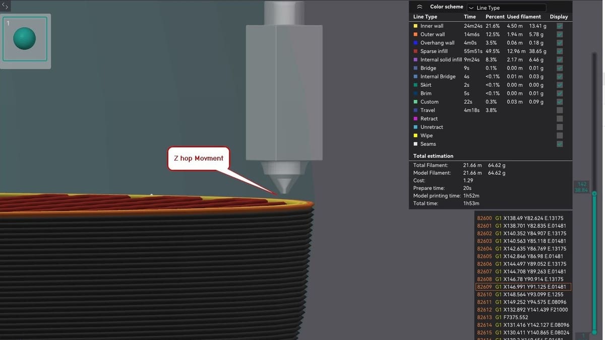
Z hop is a slicer feature that lifts the nozzle slightly when the printer moves across the print without extruding. This prevents the nozzle from grazing the print’s surface and also reduces stringing.
But if your Z-axis isn’t very precise or has a bit of backlash, the nozzle might not return to the exact same height after the hop. Over time, these tiny height differences can build up. They often show up as faint horizontal lines or bands, especially around seam areas or where travel moves happen often.
The Fix
If you notice banding around retraction points or seams, try disabling Z hop and see if the print quality improves.
Keep in mind that, sometimes, what looks like banding on one side of the print is just a visible seam. That’s where each layer starts and ends, and it usually looks like a thin line or row of tiny zits. That’s normal, not true Z banding.
You can hide the seam by adjusting its position in your slicer. For example, check out our article on seam settings in Orca Slicer.
Infill & Perimeter Patterns
The way each layer is printed can put different kinds of loads on the printer’s moving parts. If every layer always starts in the same corner, and your printer has a bit of backlash or loose belt tension with this motion, you might see a tiny shift that repeats layer by layer. Over time, this can create a visible pattern on the surface.
On the other hand, settings like alternating infill angles can sometimes cause a repeating wobble if the mechanics aren’t perfectly tight. It’s usually a small effect, but it can make other banding problems look worse.
The Fix
Try printing each layer in the same direction to reduce directional shifts, examine your nozzle’s path, or switch to a more stable infill pattern. If the banding changes when you tweak these settings, it likely means your issue is related to motion or backlash in the X- or Y-axis, not just the Z-axis.
Stepper Driver Behavior
The stepper driver is the part of your printer that controls how much power goes to the Z motor. If the settings are off or the driver isn’t working well, the motor might not move as smoothly as it should.
This doesn’t happen often, but sometimes, the motor can skip tiny steps, especially if it’s not getting enough power or if the driver sends uneven signals. When that happens, one layer might come out a bit too thin, and the next layer tries to make up for it. This back-and-forth can leave small lines on your print that look like banding.
The Fix
Check the Z motor current in your printer settings or firmware. If it seems low, try increasing it a little. That gives the motor more strength so it doesn’t struggle to move.
Environmental
Sometimes, the problem doesn’t have anything to do with the printer at all. The space around it can affect print quality in surprising ways.
Vibrations
If your printer sits on a shaky table or a shelf that vibrates, those movements can translate into layer shifts and create repeating patterns or wavy lines on the print surface.
The Fix
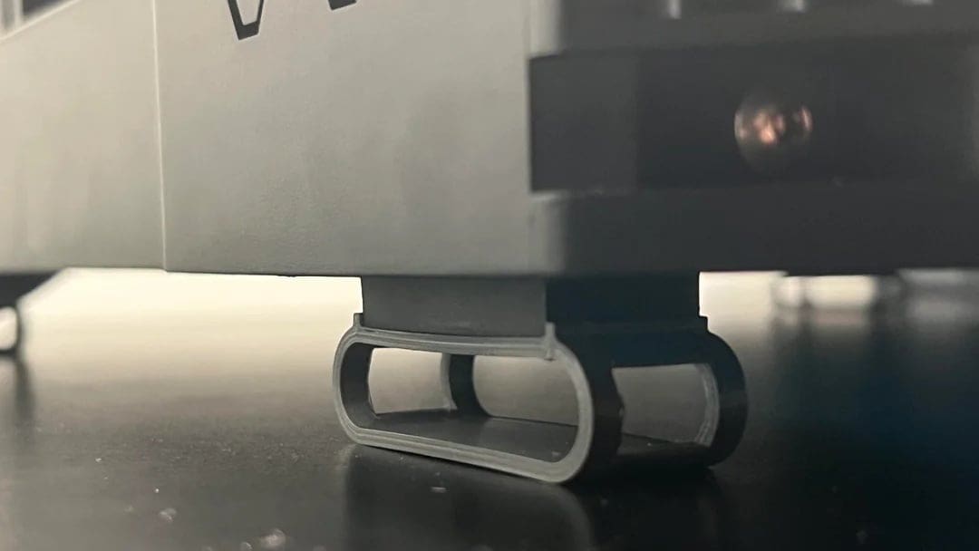
First, put your printer on a stable, heavy table. You’ll want to avoid thin or flexible surfaces. Lastly, install vibration dampening feet on your printer or place foam pads under it, as these help to reduce movement.
Temperature Changes
A sudden draft of cold air or an open window can cool the print unevenly. This makes some layers shrink differently and leave visible lines.
The Fix
Try printing in a room with a steady temperature.
Dust & Dirt
Over time, dust can settle on your lead screw, rails, or inside the extruder gears. That dust adds friction and can clog things up slightly, leading to inconsistent movement or extrusion. It may not cause big failures, but it can show up as uneven layers or artifacts.
The Fix
This problem can be avoided by regular printer cleaning. Make sure to wipe down the Z screw, linear rods, and belts with a soft cloth. Also, you’ll also want to check the extruder gear periodically for dust or filament particles.
Diagnosing Z Banding
As we’ve shown above, various different things can lead to Z banding. Before trying random fixes, it’s best to take a structured look at the issue; a smart diagnosis can save you time, filament, and frustration.
Below is a checklist that will guide you step by step through the process of determining what’s causing Z banding in your prints. Grab a notebook and camera so you can take notes and photos at each step. This will make troubleshooting easier and more focused.
Checklist
1. Look Closely at the Pattern
Let’s start with the print itself. Inspect the vertical walls:
- Are the lines evenly spaced the entire height of the print? This often points to a mechanical issue, as we previously discussed. You may have a bent lead screw or a wobbly coupler.
- Are they random or uneven? If they’re random, that could mean there are extrusion issues or temperature swings.
- Are the lines all around the part or just on one side? If it’s just one side, think about airflow, seam placement, or cooling problems.
2. Compare Banding to Your Lead Screw Pitch
If the bands show up every 8 mm, and your Z lead screw moves 8 mm per turn, that’s a solid clue. You may have a bent screw or coupler issue causing repeatable shifts once per turn.
3. Manually Check the Z-axis
There are a few things to check here:
- Start by manually moving the print bed or the gantry up and down with the power off. It should feel smooth and even.
- Turn the lead screw slowly by hand and watch the coupler. If it moves off center or flexes awkwardly, it may be misaligned, or the motor shaft could be bent.
- Remove the lead screw and roll it on a flat surface. If it wobbles or bounces, it’s bent.
- Check the rails or linear guides for looseness or binding. If your printer uses V-wheels, adjust the eccentric nuts until the gantry is stable but moves freely.
4. Check the Frame and Gantry Alignment
Use a ruler or square to make sure your X gantry is level on both sides. If one side is higher, your dual Z screws might be out of sync, or the frame is twisted.
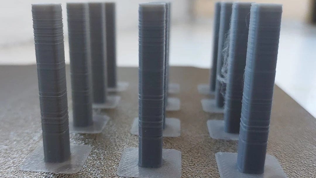
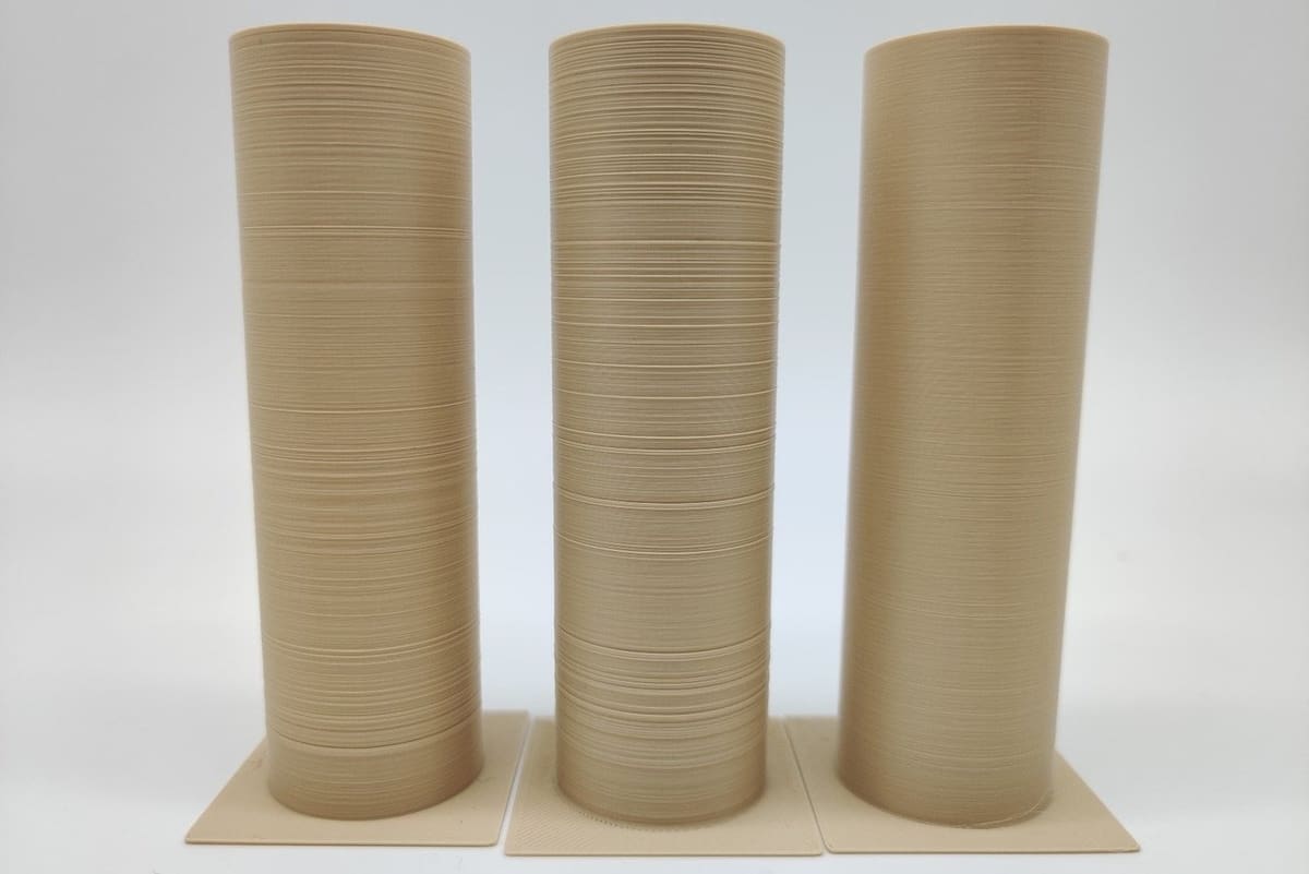
5. Print a Z Banding Test Print and Watch Closely
One of the simplest ways to spot Z banding issues is to print a tall, single-wall cylinder – for example, the Z wobble test model. This shape makes it easier to see repeating patterns, ripples, or surface distortions as the model is printed.
Do this test before and after you make a fix. It gives you real time feedback and confirms whether the issue is with your printer or caused by a specific model or design.
While the printer is running, take a moment to really watch how it behaves. You might spot something important:
- Does the X gantry wobble or sway as it moves? This might point to a loose frame or uneven Z sync.
- Does the Z screw vibrate or shake while turning? That often points to a bent screw, a misaligned or loose coupler, or even a tilted Z nut.
Also, don’t forget to check your temperatures!
- If the hot end or bed fluctuates by 5 °C or more, it could affect layer consistency. This is often caused by unstable heating or a lack of PID tuning (see the Firmware & Slicer section above).
6. Change One Thing at a Time
Still seeing Z banding on your prints?
- Try a better filament. Cheap spools with poor diameter control can create lines that look like Z banding. Swap it out and run a quick test print to see if things improve.
- Turn off Z hop to check whether it’s affecting print quality as we described in the Firmware & Slicer section above, then do a Z banding test print to check for improvements.
- Rotate the model on the build plate in your slicer, then print it again. If the banding moves with the model, it could be a model or slicer artifact. If it stays in the same machine direction, it’s likely mechanical.
7. Reach Out to the Community
If you’ve tried everything and still can’t solve it, don’t stress. Post your notes and photos to a forum or Reddit groups like r/FixMyPrint or r/3Dprinting. The community is usually great at spotting problems.
Already Printed Parts
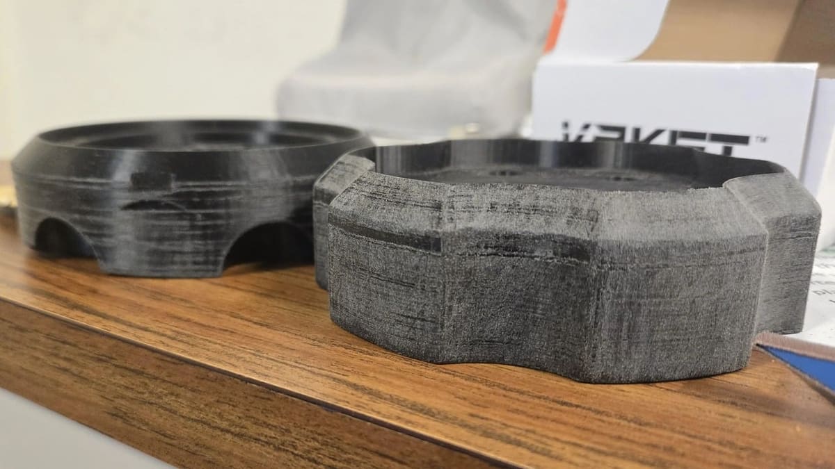
Let’s say you’ve already printed the part, and Z banding showed up. If going through the fixes above and reprinting the part isn’t an option, the good news is that you can still clean up the part’s appearance with some post-processing.
The easiest way is sanding. Start with a rougher sandpaper, like 200 or 400 grit, to smooth the big lines. Then, use finer sandpaper, like 800 or 1000, to make the surface cleaner and more polished. Take your time and sand all sides evenly.
In the end, Z banding might show up, but it doesn’t have to ruin your print or your day.
Happy Printing!
License: The text of "Make Your Printer Z Wobble Free & Banish Z Banding From Your Prints" by All3DP is licensed under a Creative Commons Attribution 4.0 International License.