G-code Generator: All You Need to Know

A G-code generator creates machine instructions for 3D printing or CNC machining. Learn more about G-code generators and how they work.
In the early days, machine tools were manually programmed and controlled. To reduce the efforts involved in programming such machines and to bring down production times (and costs) due to increasing demand for products, computer numerical control (CNC) machines started to be developed in the 1940s and 1950s.
These machines were instructed on what to do and how to do it based on a code, and given the variety of systems and hardware, it’s not surprising that different codes were used. That said, overtime, a common language evolved for CNC: G-code!
These days, CNC machines range from 3D printers to lathes, mills, and engraving machines that use lasers, plasma, or water jets! While 3D printers are CNC machines, they aren’t generally referred to as such; we’ll keep that distinction in this article.
When it comes to 3D printing, the G-code – as generated by your slicer – instructs the machine how to make your part based on your 3D printer, STL model, and your settings; this will involve defining the nozzle’s temperature and the amount of extrusion during the printhead’s move, among more. For CNC machining and cutting, the G-code instructions include controlling the coolant, establishing the tool speed, and moving the tool to execute a path or contour of engraving, milling, or cutting.
But have you ever wondered how such G-code commands are generated? Don’t worry, we’ve got you covered! Special programs called G-code generators are used to generate machine-readable commands. Read along to get an overview of how G-code generators work!
The Alphabet Soup!
As mentioned, geometric code, or G-code, is the programming language used to program computer numerical control (CNC) machines – 3D printers included. In order to perform operations and tasks using a CNC machine, the instructions need to be provided in a machine-understandable format.
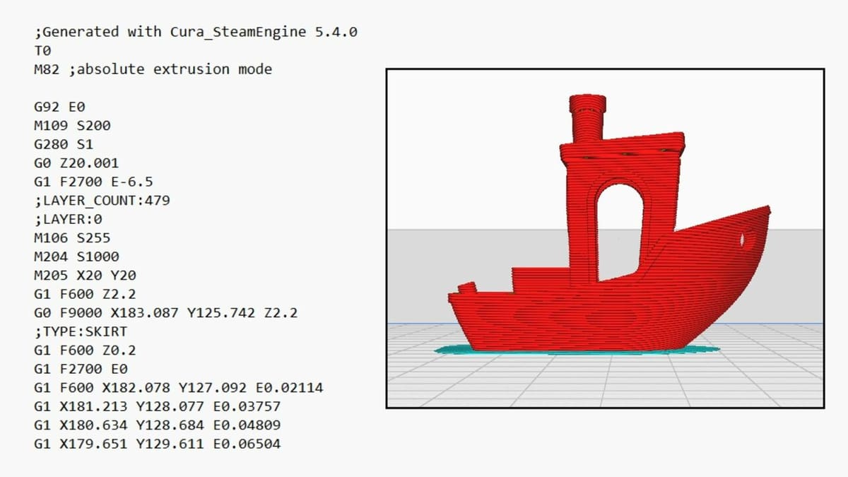
Commands in the form of one-liners and following a structured syntax make up a G-code file. Many G-code commands begin with the letter ‘G’, but in fact, all letters of the alphabet are used. Codes beginning with ‘G’, ‘M’, ‘X’, ‘Y’, and ‘Z’ are the most common. In 3D printing specifically, ‘E’ and ‘F’ are used for extrusion and feed rate. The commands are sequentially executed to perform the tasks.
If you see “Gxx” (the ‘x’ denoting a digit), that’s a preparatory code. Many of these move the working parts of a machine. For example, G0 and G1 are commands used to define linear motion, G90 and G91 are used for absolute and relative positioning respectively, and the command G28 is used to move the tool or extrusion nozzle back to the Home position.
“Mxx” codes are the miscellaneous commands, controlling things like coolant, spindle speed, fans, and heaters, and ‘X’, ‘Y’, and ‘Z’ define the coordinates.
With a clearer understanding of what G-code is and how it works, let’s take a look at different generators.
What's a G-code Generator?
Generating G-code means creating a full description of how to make something with a machine. Originally, G-code was hand-coded – imagine that! For a simple machined part, this can work. With an understanding of machining, knowledge of the relevant G-code commands, and some copy and paste, anyone can create the full G-code recipe for a machined part. However…
Slicers (3D Printing)
Fused deposition modeling (FDM) 3D printing creates smooth, attractive parts because it uses a small nozzle to extrude thin layers of plastic. Even a small printed part can have hundreds of layers, each with hundreds of small motions, meaning tens of thousands of lines of G-code.
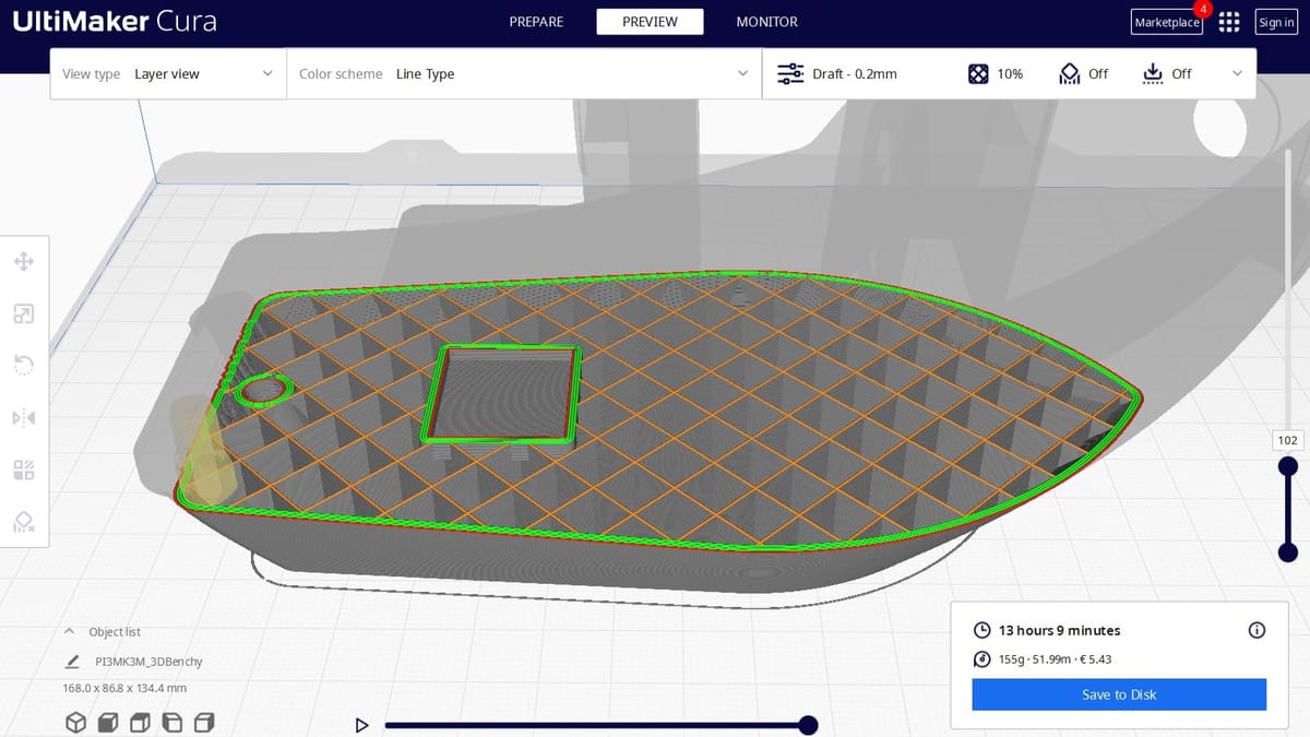
For that kind of recipe, hand coding can be a problem. For 3D printing, G-code generators are called slicers because they “slice” an STL file into layers that can be extruded as an outline with cross-hatching or infill. Your slicer takes into account layer thickness, infill percentage, support, adhesion, extrusion, and bed temperature to generate a G-code recipe for your part, which can be understood by your printer.
Each motion of the printer is given, for example, to trace the perimeter, cross-hatch, or trace interior holes. A slicer also takes into account the extrusion temperature, fan, and speed requirements for running a particular material on your machine!
After slicing the model, you can export the G-code. If you have your 3D printer connected to your PC via cable or Wi-Fi, you can directly send the G-code file from the slicer to your machine. You can also upload the code via a USB stick, depending on your setup!
Other Generators (CNC Machining)
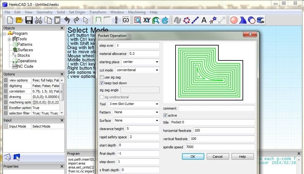
CNC machining may take a different approach to manufacturing than 3D printing, but it can also get involved. When cutting even a single pocket or through-hole, it takes several passes around the same path at increasing depths to make the complete feature. And even then, a finishing cut, removing a final layer of material, is typically used to get the best surface finish.
Other details that are hard to add by hand are tabs. These small bridges or breaks in the contours of the part keep it attached to the parent material. A CNC router code generator can add these easily. Automating the creation of multiple passes, finishing cuts, and tabs are just some of the ways a CNC router code generator simplifies the G-coding process.
Similar to 3D printing slicers, once you have everything set up for the code generation and the CNC router code generator has finalized the machining path, the G-code file can be generated and transferred to your CNC machine.
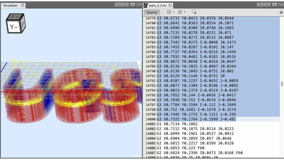
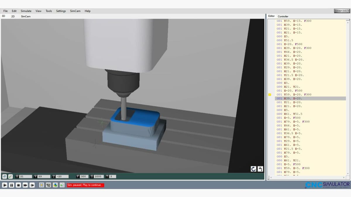
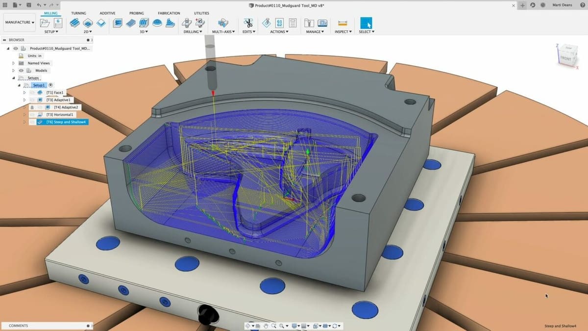
Some code generators also provide the ability to simulate the generated G-code, where the tool machining path or contour is simulated. This can be used as a premature check for tool collisions or correctness of the generated code, before the actual machining commences on the CNC machine!
Generation: How It Works
Since CNC machines perform repetitive operations, the same basic cycle can be repeated. Let’s take a look at some of the steps that go into creating G-code, which are automated by a G-code generator.
3D Printing
After dividing an STL file into layers, the basic cycle for generating G-code for each layer is as follows:
- Identify the outlines, both exterior and interior, in order to determine what’s “inside” and “outside” the layer.
- Determine how infill will be laid within the interior of the layer.
- Create an optimized traversal of the layer’s extrusion for outlines and infill.
- Set the speed, extrusion, temperatures, and fan speed.
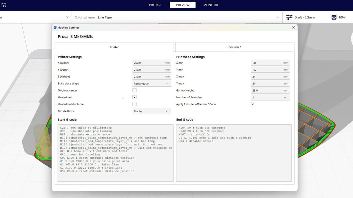
- Create ‘G’ and ‘M’ codes for the start and end.
- Convert the full traversal path into “Gxx” movements, adding extrusion ‘E’ and feed rate ‘F’.
For more on how a slicer works, step by step, take a look at this DIY G-code generator on Instructables.
CNC Machining
Parts to be CNC milled are similarly divided into depths, where a cycle is repeated at each layer:
- Set exterior or interior for pockets or through-holes.
- Set the depth of cutting and passing required to produce the full contour height.
- Set the tool diameter or kerf (the cutting diameter of a laser, plasma, or a water jet).
- Set tool alignment to be inside or outside of the path.
- Set the spindle speed or cutting intensity.
- Create ‘G’ and ‘M’ codes for the start and end.
- Create positions for the path, including multiple passes at depth of cut to create the full contour.
- Convert the geometry into “Gxx” motions.
For more on how to create CNC G-code, take a look at our detailed tutorial on CNC programming.
Examples
To give you a little taste, here are some sample G-codes.
The following line homes X and Y:
G28 X0 Y0;
This one instructs a linearly interpolated movement using absolute X and Y coordinates:
G01 X61.888 Y127.862 E19.90544
Here are two special codes for 3D printing:
M107; (start with the fan off)
M109 R245; (set the extruder temperature to 245 °C and wait)
And here are two for CNC lathes and mills:
M03; (spindle on, clockwise)
M08; (coolant on)
Generators
While UltiMaker Cura and Autodesk Fusion 360 are arguably among the most known G-code generators within the hobbyist community, there are a plethora of other options out there.
One of the great things about 3D printing is that STL files are light since only the data on surface geometry is stored. This also means that you don’t need a beefy program (as is the case with CNC machining) to generate your G-code!
For 3D printing, there are a variety of 3D slicer software, with ideaMaker, Simplify3D, and PrusaSlicer being among the most popular, in addition to Cura. ideaMaker offers fast slicing speeds even for large files since it uses a native multi-threaded compiler for slicing. The other two slicers are aimed at advanced users as they offer the ability to tweak every single parameter you can think of and also manually program certain bits!
For CNC machining however, the story is a little bit more complicated. There are tools that help automate the G-code creation while leaving the understanding of the geometry to the user. You can see an example with this Excel-based G-code generator and a related tutorial video.
Alternatively, you can start with a 2D source file, like a PDF, DXF, or an image. The program does the heavy lifting of interpreting the paths in the drawing or image. Some examples are Cut2D, FlowPath for water jet, DXF to G-code, and PixelCNC for images. There’s even an Inkscape G-code plotting extension for creating cutting programs from Inkscape designs. In our other article, we cover four easy ways to convert DXF to G-code files.
Lastly, the most sophisticated G-code generators are computer-aided manufacturing (CAM) ones. These tools interpret a broad range of files, including 3D solid models, and use them to automate the full G-code creation process. One such versatile tool that provides CAD and CAM functionality in one single package is Autodesk’s Fusion 360.
License: The text of "G-code Generator: All You Need to Know" by All3DP is licensed under a Creative Commons Attribution 4.0 International License.