AutoCAD 2023 Tutorial for Beginners: 6 Steps to Success

Just what you've been waiting for: an AutoCAD tutorial for beginners! Learn how to use AutoCAD in six straightforward steps.
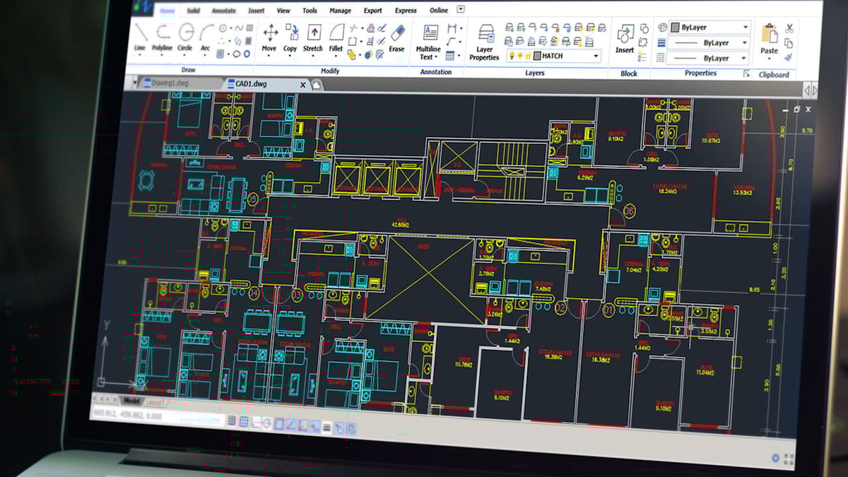
AutoCAD is arguably the most known CAD software worldwide. First released by Autodesk in 1982, it’s now used for a wide range of applications, including architectural plans, layouts, and product manufacturing drawings. This versatility has made AutoCAD a standard for some industries.
In this tutorial, you’re going to learn the basics of how to use AutoCAD and create your first designs in just six steps. We’ll first learn how to get around and then jump right into 2D sketching. After that, we’ll move on to discover its 3D modeling and technical drawing tools. Last but not least, let’s learn how to work with mesh files, including exporting STL models for 3D printing.
There’s a lot of ground to cover, so let’s dive in!

About the Software

Before getting started with the tutorial, let’s introduce the software.
AutoCAD is developed and maintained by Autodesk, the software giant that also offers other CAD and 3D modeling programs like Inventor, Revit, Maya, 3ds Max, Tinkercad, and Fusion 360.
AutoCAD is professional design software, so the price is steep at $1,775 per year. Luckily, students and educators get unlimited free access for up to a year. If that’s not your case, there are some free alternatives to AutoCAD, as well. Additionally, Autodesk offers a 30-day free trial for anyone, which is more than enough time to follow along with this tutorial and learn if it’s the tool for you!
To download AutoCAD, you’ll first need to set up an Autodesk account. There are versions for both Windows and Mac, which vary slightly in terms of UI, but the installation processes are very straightforward.
Step 1: Know the UI
Ok, now we’re ready to play with the software. In the first step of this tutorial, we’ll get acquainted with the user interface and learn how to interact with and set up the workspace.
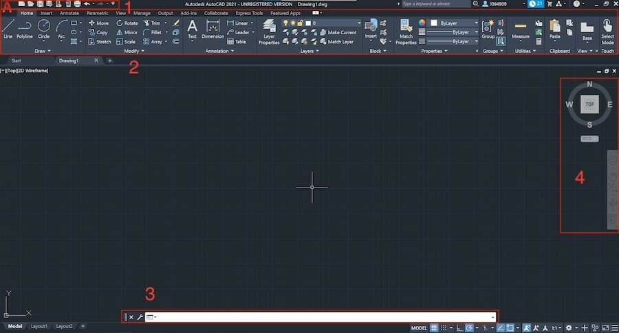
To start a new project in AutoCAD, click “New” on the left side panel. This is AutoCAD’s main working screen, where all 2D and 3D designing takes place. Basically, it’s composed of the following:
- Quick Access Toolbar, with all the basics icons for actions like creating, opening, and saving projects. This can be easily customized, as we’ll see.
- Ribbon, containing various tools and commands arranged in tabs. A ribbon-style toolbar is common in CAD software as it accommodates a huge number of tools in a compact interface.
- Command Bar, where the user can enter commands manually by typing them here. It also lists the order of required steps to execute any given command and plus some extra tips.
- Orientation tools, like the View Cube and NavBar, will be described in more detail next.
1.1: Basic Orientation
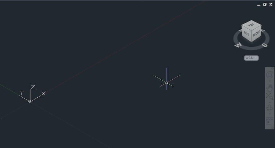
The View Cube, in the top-right corner, is set to the top view by default. If you hover your mouse over it, a little house symbol will appear. Click on it to enter isometric view.
Now you’ll see a 3D Cartesian coordinate system in the middle of your drawspace, with three axes, and the View Cube has changed position. You can click on its faces, edges, and corners to go to the desired view.
The NavBar contains other orientation tools, but usually for CAD software, mouse shortcuts are preferred. To pan around the drawspace, simply hold down the wheel button and move the mouse around. Alternatively, click on the “hand” (pan) icon on the NavBar.
Hold down the Shift key and the mouse wheel together and, instead of panning, you’ll be orbiting the drawspace around the center of the coordinate system. There’s an Orbit button on the NavBar, too.
This covers the basics of drawspace orientation. Next, we’ll finish setting up the workspace so we can start 2D sketching.
1.2: Setting Up the Workspace
First, let’s bring out all the 3D modeling tools we’ll need to complete this tutorial.
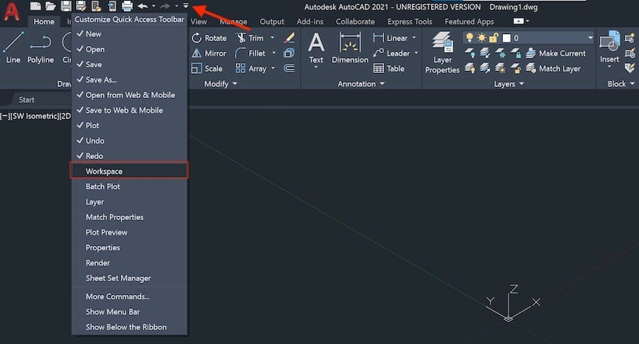
Looking at the Quick Access Toolbar, click on the downward extend arrow to customize this toolbar. A dropdown menu will pop up; click on “Workspace” to enable this feature.
Now the Quick Access Toolbar will display a new button. By default, it’s “Drafting & Annotation”, but let’s change it to “3D Modeling” by clicking on it and selecting this choice from the dropdown menu. This will allow us to use all 2D and 3D tools required for our tutorial.
Lastly, to change units, click on the AutoCAD logo in the top-left corner. This will open the AutoCAD menu. Go to “Drawing Utilities > Units”. In this tutorial, we’ll use the metric system, so change the “Insertion Scale” to millimeters.
Now we should be all set to start designing!
Step 2: 2D Sketching
Before we drill down into three-dimensional objects, let’s have a look at 2D sketching first. AutoCAD is most known and used for its drawing capabilities, such as floor plans and layouts.
2.1: Snapping
Grip snapping is a great feature for sketching with AutoCAD. To enable Grid Snap, simply press F9 on your keyboard or click on enable “Snap to Drawing Grid” at the bottom right-hand corner.
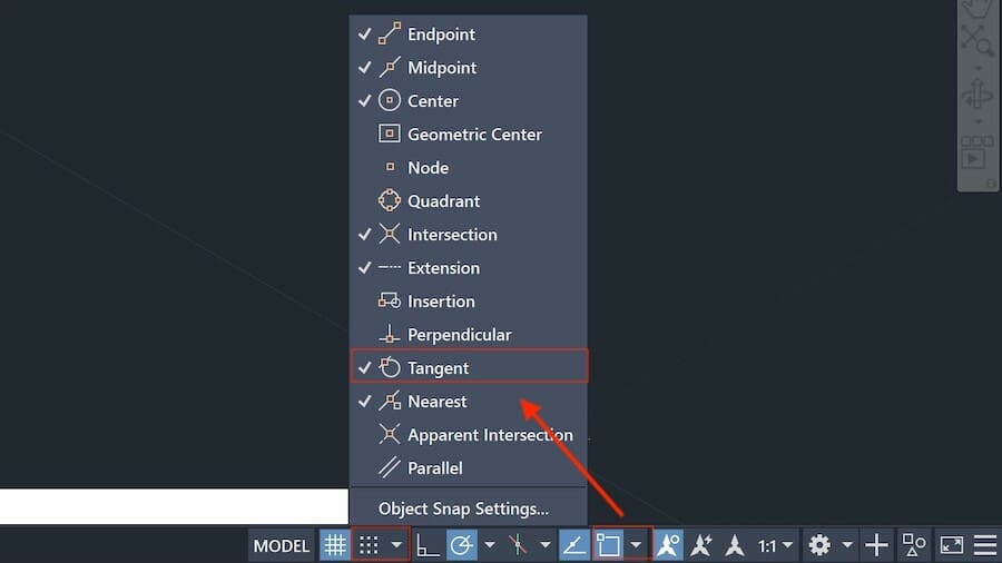
Click on the extend arrow next to the “Snap to Drawing Grid button” and select “Snap Settings…”. This window allows you to adjust the grid as well as the accuracy of the grid snap. Go to the “Object Snap” tab and enable it.
Now, by pressing F3, we can activate snapping to corners, lines, points, and midpoints, among many options. To select object snapping constraints, click on the extend arrow as shown. Click on “Tangent” to make it active, as shown above.
If you have problems with entering coordinates or sketching, try toggling “Snapping” on or off, and try not to use Grid and Object Snap simultaneously. This tool is useful to draw sketches fast and to prevent holes in your sketch.
2.2: Drawing Lines
To create your first sketch, select top view by clicking the View Cube and disable Grid Snap with F9.
Now either select the line command on the Ribbon or type in “line”. With AutoCAD, you can simply type in the first letters of any command, and the software will autocomplete and show any available commands.
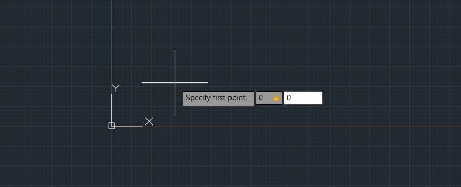
Once you’ve entered the line command, it’ll ask you to specify the first point. You can either click a random point in your drawspace or enter the coordinates manually.
Enter 0 for the X-coordinate, change to the Y-coordinate input field by pressing Tab, and enter 0 there as well. Press Enter to confirm.
You’ve now selected the center of the coordinate system as the starting point of your line, also known as the CenterPoint, located at the coordinates (0,0).
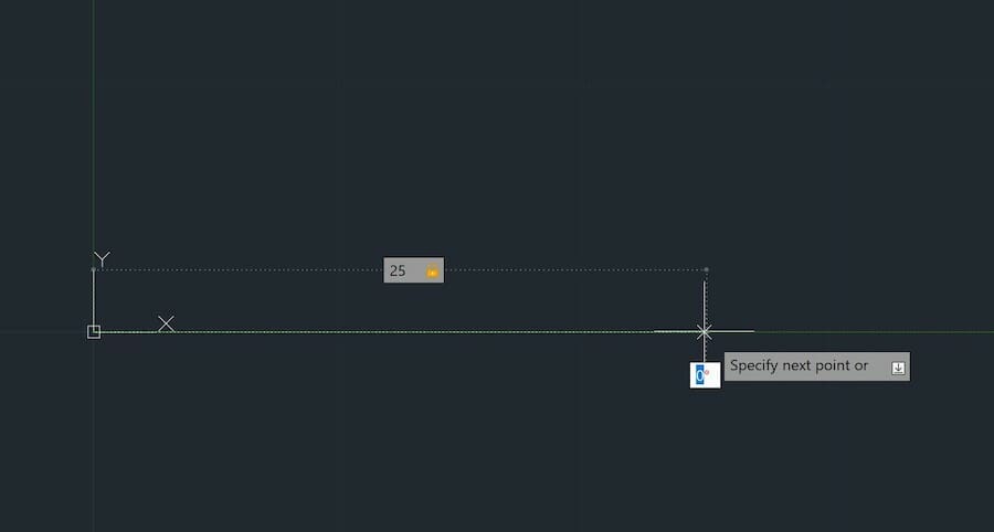
Now move your mouse up along the Y-axis. Note that the coordinate input will have changed from Cartesian to polar coordinates.
Enter 25 for the length of the line and, by pressing Tab, enter the angular input of 0. Press Enter: You just drew a line!
Try sketching a complete square now. Notice the angle value is always relative to the origin, so you’ll have to enter the angle values accordingly. Once you return to the center, press Esc to exit the line command.
2.3: Selecting Objects
To select drawn objects, simply left-click on them. Unselect by holding down Shift and clicking again.
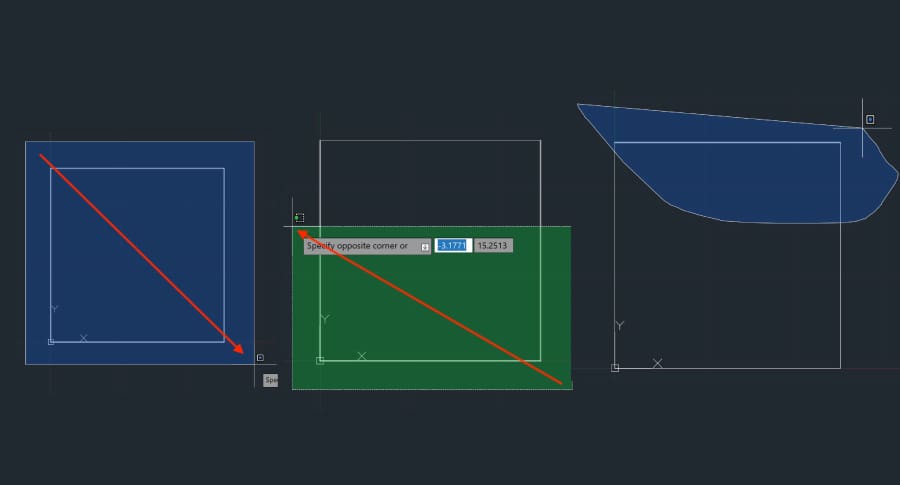
Select multiple objects by left-clicking (not holding) and moving the mouse from left to right. This will select all objects fully enclosed within the blue rectangle. Now, when you drag from right to left, you’ll select all objects touched by the green rectangle. Click once again to confirm the selection.
Clicking and holding the left mouse button will enable the lasso, which lets you select a random shape. With that, practice a little by selecting your square in a couple of different ways. Once you’re done, select it once more and either press the Delete key or type “delete” to erase it.
2.4: Drawing Shapes
Naturally, AutoCAD offers easier ways to draw simple shapes. Let’s draw a few shapes to create a new form. Stay with us, we promise we’re going somewhere.
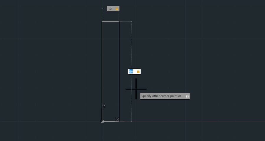
Click the “Rectangle” icon on the ribbon or type it in on the command bar. Now, enter the rectangle origin as (0,0), just like we did for the line, and hit Enter.
Then, the rectangle command will ask the opposite corner coordinates. Enter the values of (10,60) and press Enter. (Note that, for this command, the Cartesian coordinates are kept, and the Object Snap must be turned off for the line to intercept the circle properly.) That’s it!
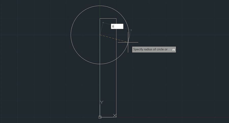
Next, let’s make a circle with its center at (0,50). Confirm the coordinates by pressing Enter. Then, set the radius to 8 mm.
If you made a mistake, simply double-click on the sketch you want to edit. Edit the values in the pop-up window.
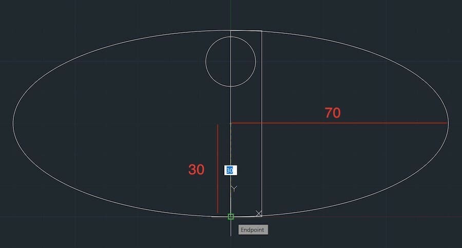
Next, create an ellipse centered at (0,30). Set the major radius (parallel to the X-axis) to 70 mm and the minor radius to 30 mm, like the image below.
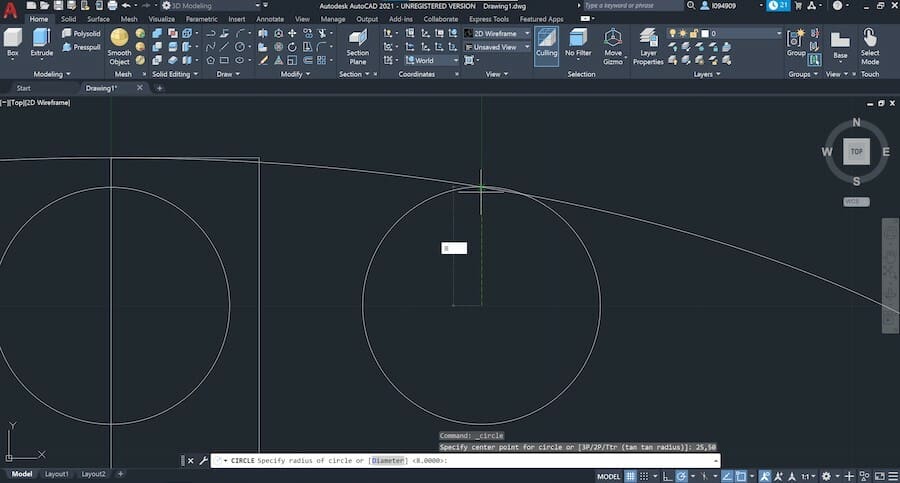
Now, draw a second circle centered at (25,50) and turn on Object Snap by pressing F3. Without typing any values, guide the circle’s radius to the Y-axis until it intersects with the ellipse, and left-click when you see a green cross.
Let’s create a couple more lines. Draw a line starting at (10,55) and finish it tangent to the second circle. Click to confirm the final point of the line when the little green tangent icon appears.
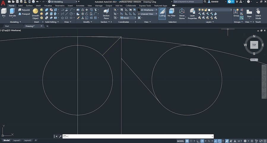
Start a second line at the top right corner of the rectangle (10,60). Then, input an angle of 135° and intercept the first circle with the line.
Now you should have something like the image above.
2.5: Spline
Next, let’s draw a spline. With the Spline tool, you can create continuous curves between connecting points.
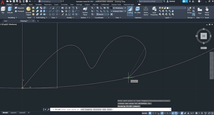
Create a spline starting at the center point (0,0). First, you add a distance, followed by an angle. Then press Enter to go to the next point.
Enter the following polar coordinates: (20,30°), (5,300°), (5,55°), (10,30°), and (5,320°). For the last point, leave both values empty and manually intercept the ellipse like shown above. Now type in ‘T’ and hit Enter to end tangency. Press Enter once again.
You might already see what’s coming. We’re almost there.
2.6: Trim
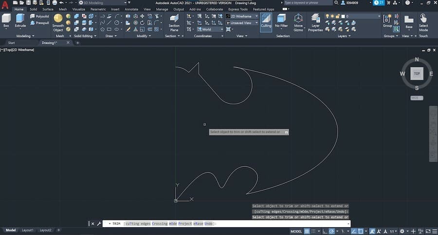
The Trim command is used to remove extra lines up to an intersection.
Start by typing “trim” and click on a line segment to erase it. You should end with the image above. If you removed a line by mistake, click on “Undo” on the Quick Access Toolbar.
Be sure to take a close look at any lines stuck in between small edges. Those would likely become a problem if we were going to 3D model it. Hit Enter to confirm the trim once you’re finished.
2.7: Mirror
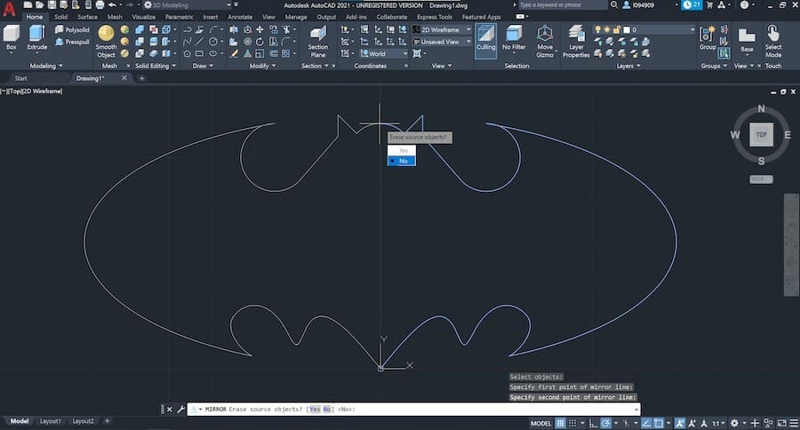
For this last step, we’ll use an important sketch tool: mirror. When drawing symmetrical sketches, it comes in handy to simply draw one half of a sketch and then mirror it.
Type in “mirror” and then select the entire sketch and confirm with “enter”. Select CenterPoint (0,0) as the first point of mirror line and for the second point a positive coordinate along the Y-axis.
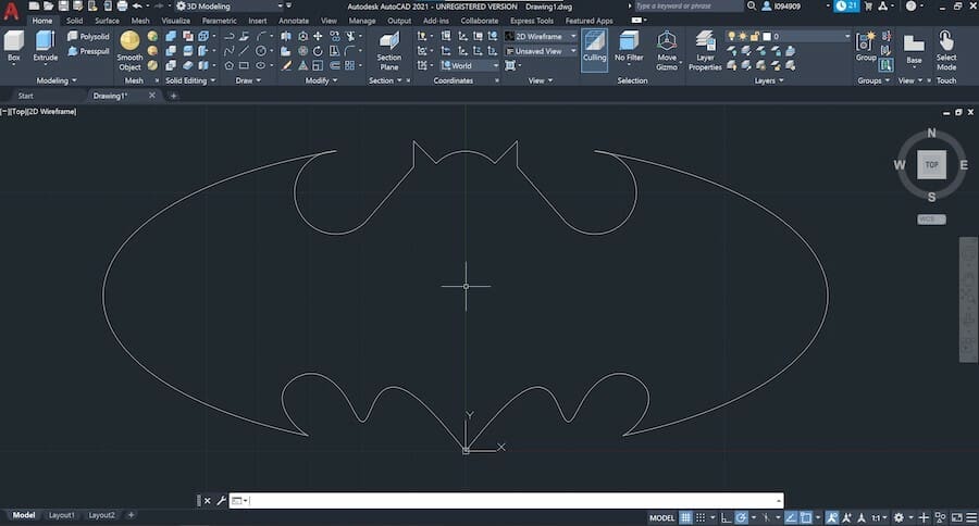
Click “No” on the question to remove the source object. That’s it! Congratulations! You’ve now sketched your first 2D draft in AutoCAD!
Step 3: 3D Modeling
3D modeling might be one of the most interesting parts of this tutorial. Going 3D will allow you to design your own models for 3D printing.
3.1: Creating Basic Shapes
Let’s start with some direct modeling tools. This is when we use predefined shapes like spheres and cubes to create objects via Boolean operations (union, subtraction, and intersect).
First, switch to the isometric view through the View Cube by clicking on the little house icon.
Now let’s start by creating a perfectly round body. Type in “sphere” and center it at (0,0). Once that’s set, move your mouse around it to gain form. Alternatively, enter a value for the radius which in this case is 10 mm.
This how you create basic three-dimensional shapes. Easy enough, right? Still, the object doesn’t really look like a solid yet. Let’s change that.
3.2: Changing Visuals
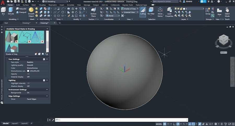
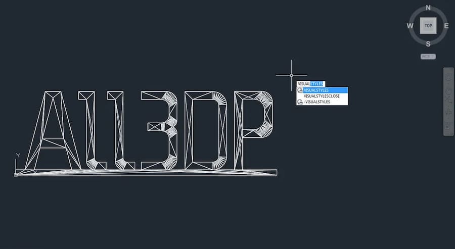
If you want to change the visual effects when displaying 3D objects, you can do so by typing in “visualstyles”. A new window will open where you can choose the visual style you prefer.
Let’s change the visual style from “2D Wireframe” to “Shades of Grey”. That’s looking more like it!
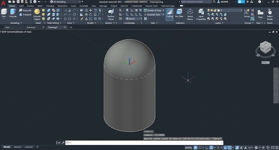
Now, let’s try some of the Boolean operations mentioned before. First, let’s create a cylinder that overlaps the sphere we just created.
To do that, type in “cylinder” and draw the base of the cylinder just like you would a simple circle. Choose the CenterPoint (0,0) as the origin and go for a 10 mm radius. Next, similarly to the sphere, move the mouse downwards to see it extrude. Set its height to 25 mm and confirm by pressing Enter. Now we should have something like this:
The first operation we’ll learn here is union, where objects are merged. The sphere and cylinder might look like one piece but they’re still two separate parts.
To join them, type in “union” and select both shapes. Confirm the operation by hitting Enter, and now you should have one solid body.
Another basic operation is subtraction. Let’s reverse the last union operation first by clicking on “Undo” at the Quick Access Toolbar.
Now type in “subtract” and enter the command. First, we need to select the object to subtract from. Select the cylinder and confirm by pressing Enter. Then, select the sphere as the object to subtract and confirm.
And there you should have it, the shape of the sphere has been carved into the cylinder.

The last Boolean operation is to intersect the objects. This should keep only the areas that two or more objects overlap. Let’s undo the subtract operation and try intersecting these objects.
Type in “intersect” and select the sphere and cylinder. By confirming the operation, you’ll see the results as a hemisphere. This is because the cylinder only overlaps the bottom half of the sphere.
With basic shapes and these three simple operations, we can design a huge range of parts already. Next, we’ll see how solid modeling works in AutoCAD.
3.3: Solid Modeling
Instead of playing with basic shapes to construct an object, the more complex models require a different approach altogether. For this, either create a new drawing or delete anything that’s currently in your drawspace.
The tools we’ll see next are common in the 3D CAD world, mostly being referred to by the same names. Let’s start out by creating a simple 3D polygon with one of the most useful features: Extrude.
3.4: Extrude
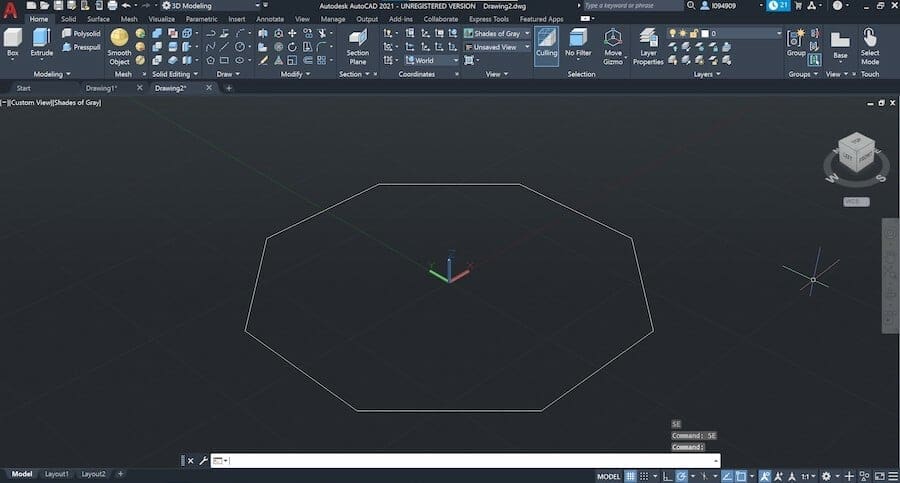
Start by creating a 2D sketch of an octagon. Type in “polygon” and press Enter. First, set the number of sides to 8, then select the CenterPoint (0,0) as the center, and click on “Circumscribed about circle”.
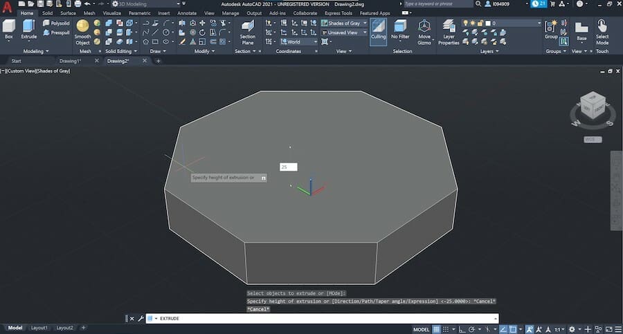
Enter an 80 mm radius and confirm. Now to the fun part. First, type in “extrude” and press Enter. Select the 2D octagon shape we just drew and again press Enter to create a 3D object.
If you move the mouse upwards you’ll see the polygon extrusion. Set the height to 25 mm and confirm it with the Enter key. The extrusion operation can be made with any sketch as long as it’s a closed shape.
3.5: Revolve
The next feature in our tutorial is called Revolve. This is an uncomplicated way to design shafts or objects with line symmetry. Clear your drawspace and let’s get going.
Once more, start by sketching the object. Start a line at the CenterPoint and follow the ‘E’ shape, as shown above, creating lines until the shape is closed.
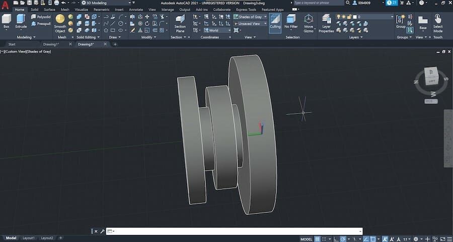
Now, to make this solid, type in “revolve”. First, select everything and confirm. Now, for the rotation axis, type in ‘Y’ and press Enter. (You should see the shape rotate around the Y-axis.)
Set the angle to 360° for a full rotation and confirm. This will create a solid object. Interesting, right?
3.6: Loft
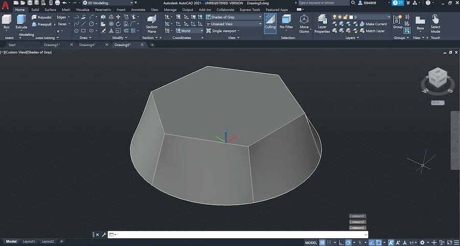
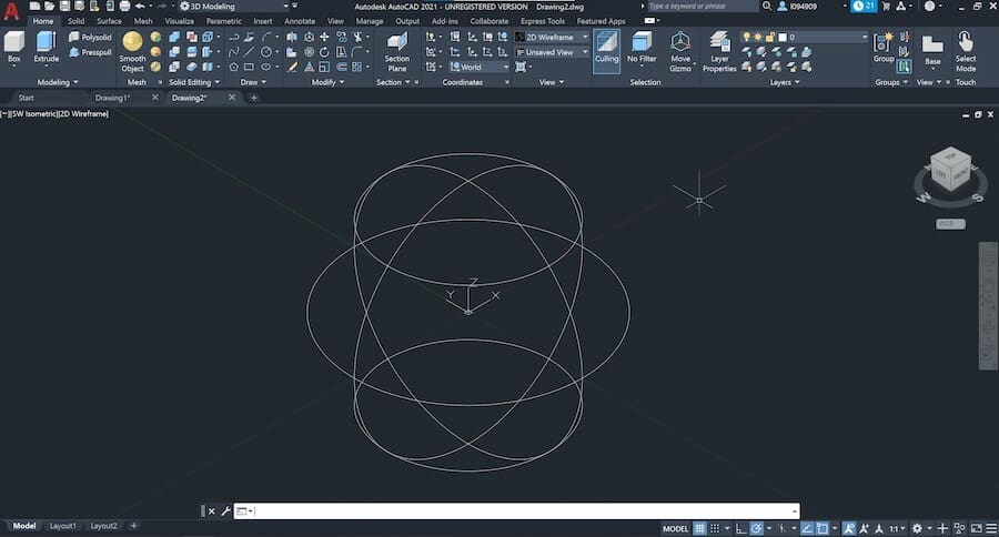
Now, let’s learn a couple of other features for creating solids. We’ll start with Loft. First, clear your drawspace or create a new project.
Draw a circle on the CenterPoint with a radius of 100 mm. Then, create a hexagon at a higher plane. To do that, type in “polygon” and select 6 sides. Before entering the coordinates for its center, click on the command bar and type in “0,0,50”.
This will tell AutoCAD to create the sketch on a plane parallel to XY but at a 50 mm height. Finish the polygon by entering a radius of 80 mm.
Type in “Loft” to start this feature. Select both the circle and the hexagon, then press Enter. Select “Cross Sections only” to finalize the tool.
This will connect both shapes and create a solid within. It’s a great way to combine non-matching shapes like circles and polygons.
3.7: Sweep
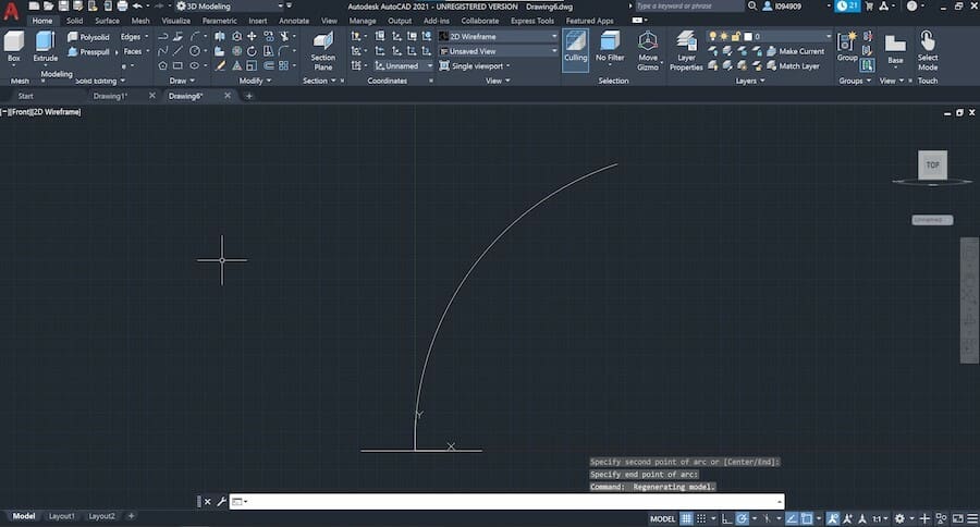
The Sweep feature comes in handy when designing curved structures. To do a sweep, you’ll need to sketch a base geometry first. Draw any polygon you like on the CenterPoint.
Next, we need to change the coordinate system to draw on another plane other than XY. To do this, go to the Front view, type in “ucs” and then “v” to make this the new Top view.
Now, draw an arc at the origin (0,0) by typing “arc”. This will be the sweep path. Draw a wide arc, not crossing itself, similar to the image above.
Finally, type in “sweep”, select first the drawn arc, and confirm. Then select base and once again press Enter. You should have your solid body.
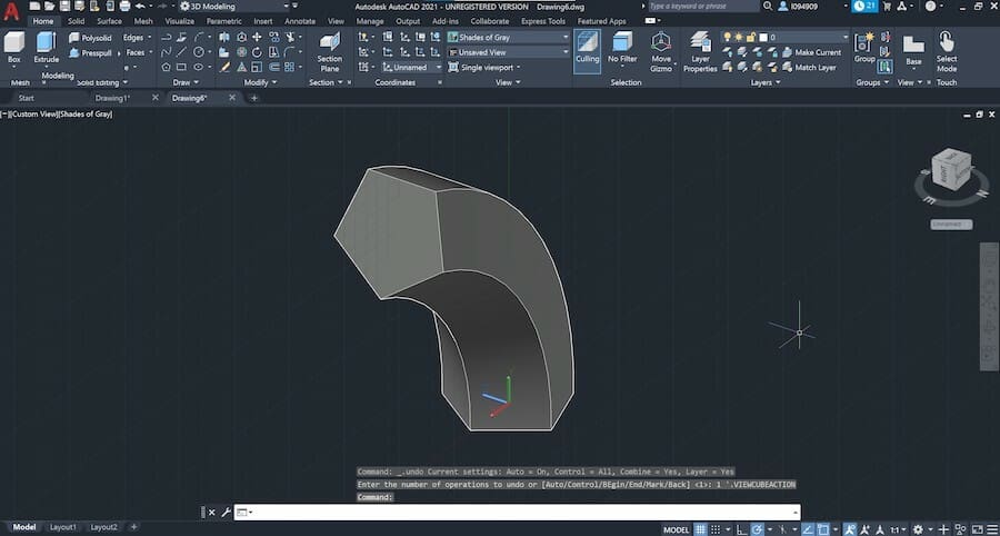
While the feature looks simple, it allows us to make highly complex objects.
That’s it! We’ve covered a lot of ground. So far, we’ve learned the most important tools for 3D modeling, from handling basic shapes to the more traditional CAD features. Next, we’ll look at how to manipulate these objects.
Step 4: Moving & Aligning Objects
We should be able to 3D design almost any part in AutoCAD with the features and techniques learned in the previous step.
However, objects can also be composed of multiple parts that are “assembled” together. Let’s find out how to move and assemble different 3D models.
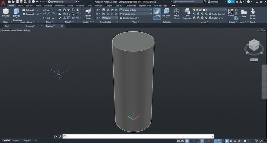
Basics first. Moving an object is a very straightforward operation that can be done in multiple ways. Start by creating a cylinder centered at (0,0), 100 mm in diameter, and 500 mm in height.
4.1: 3D Move
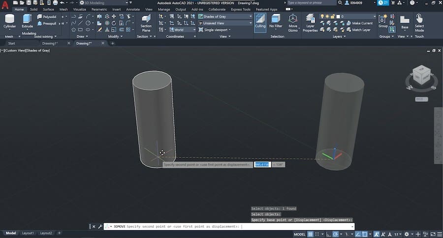
Now, let’s move out from the origin. Type in “3D move” and confirm the command. The first thing to do is to select the parts to move. In our case, select the cylinder and press Enter.
Next, we need to select a base point for the move. With your mouse, select the center point of the cylinder’s base. Hit Enter to confirm.
Once we’ve confirmed what we want to move, there are various ways to move the cylinder around: with the mouse through the XY plane or by entering a distance and direction for the move through polar coordinates.
We can also perform linear translations through the XZY axes. Note the three-axis arrow shape at the center of the cylinder. Click on the blue one (Z) to move it vertically with the mouse or by entering the distance.
This last move operation can be done by simply selecting the object. You’ll note that the arrow axis will be displayed.
4.2: 3D Rotate
We can also manipulate objects through simple rotation. This is especially useful for objects that are sketched in the XY plane but require repositioning.
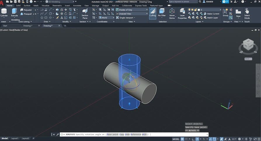
Let’s lie down our cylinder. Type in “3D rotate”, select the object, and press Enter. Note the three circles now surrounding the cylinder. Each corresponds to a rotation axis and is colored accordingly.
For example, if we wanted to rotate an object through its Z-axis, we would use the blue handle, which is the color of the Z-axis.
Now, let’s give our cylinder a 90° rotation through the X-axis. Click the red circle. Note that the cylinder will rotate around this axis when you move the mouse. Either spin it to 90° or enter the value and confirm.
4.3: Align
Both the 3D Move and 3D Rotate tools allow us to fully manipulate objects in space. Sometimes, though, we require something faster and perhaps even more intuitive to move and place bodies.
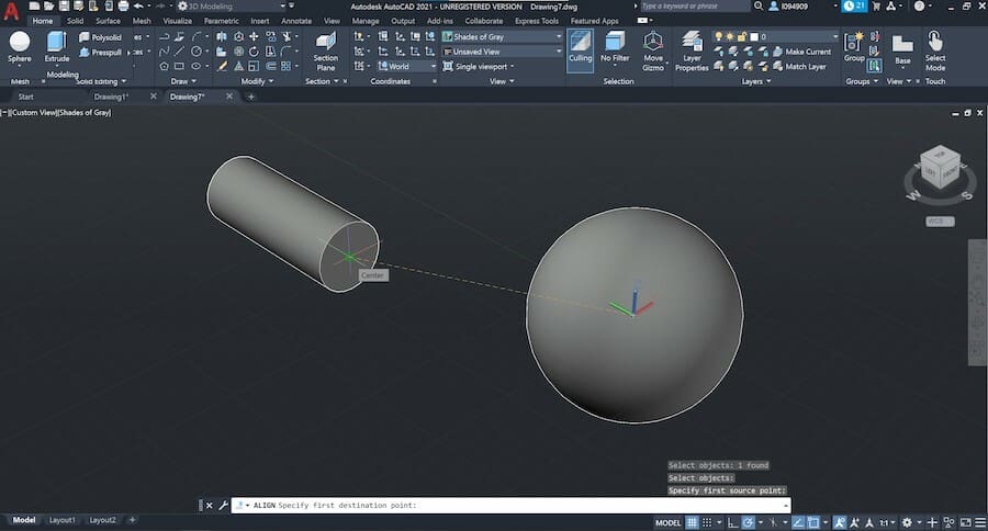
This is where 3D Align comes in. With this, we can quickly position two or more objects in relation to each other, so don’t delete your cylinder yet! Let’s create a sphere 30 mm in diameter centered at (0,0).
Type in “align” and confirm the command. Select the sphere only and press Enter. Now, select the center of the sphere as the base point and then select the center of one face.
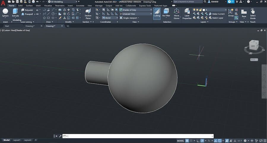
A straight line will be drawn, representing the movement of the sphere. Confirm with Enter and you’ll see both shapes aligning. Cool, right?
This can be quite useful when using basic shapes and Boolean operations, as you can imagine.
Step 5: Working with Technical Drawings
AutoCAD is a great tool for generating technical drawings of models created in 3D.
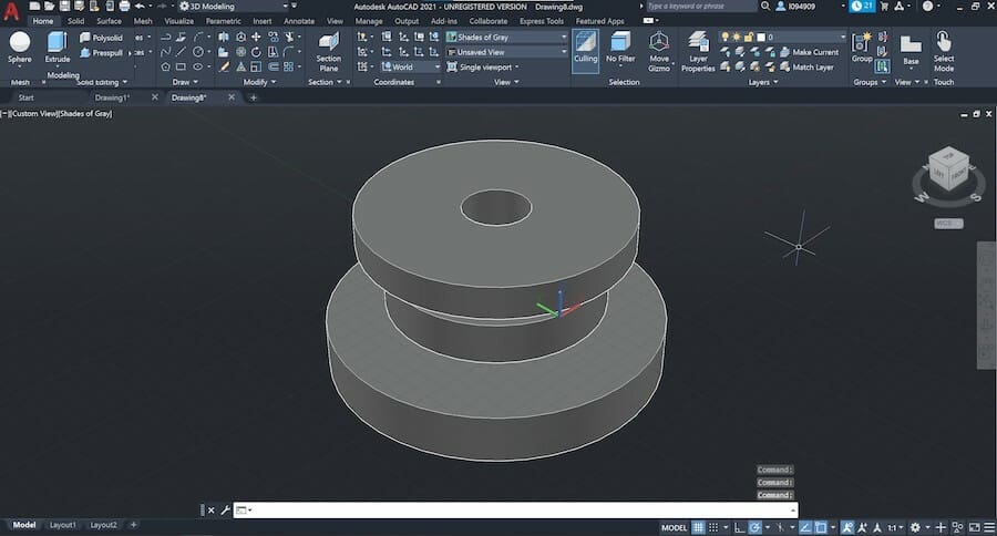
We’ll first need a model and template sheet for our drawing. We’re using the part we created in step 3 using the Revolve feature, with the only difference being the 40 mm hole on the central axis.
For the template, we’ll use one from AutoCAD for now but you can find many other models online or even design one for yourself.
Make sure only the part we want to detail is in the drawspace. Then right-click on the “+” in the bottom left corner and click “From Template…”. Select the “Tutorial-mMfg” template that comes with AutoCAD.
This will open a new window with the template sheet we selected. You can put your name and the project’s name in the title block at the bottom right of the sheet by double-clicking it.
5.1: Inserting Model Views
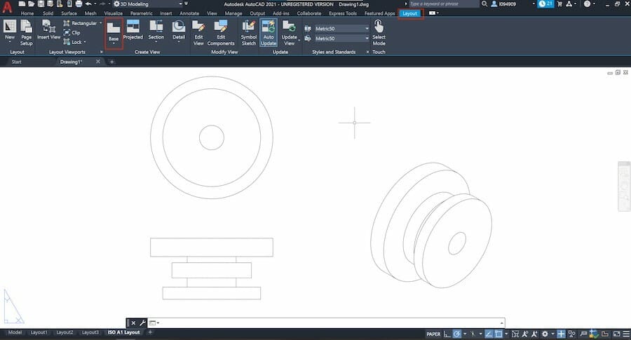
Go to the “Layout” tab on the Ribbon, then click “Base > From Model Space”.
Click to place the first view, which is Front by default, in the middle of the sheet. You’ll notice a small options window will pop up.
Here you can switch the view to a different one by clicking on “Orientation”. If the model is too large or small, click on “Scale” and change the scaling factor. For our model, set the scale to 1:2.
Click on “Exit” from the options window to confirm that view. You can now continue to place other views by dragging the mouse horizontally or vertically.
Create a Top view under the first view as shown. Then, move the view from a 45° angle to create an isometric view at the lower right corner. Type ‘X’ and press Enter to finalize.
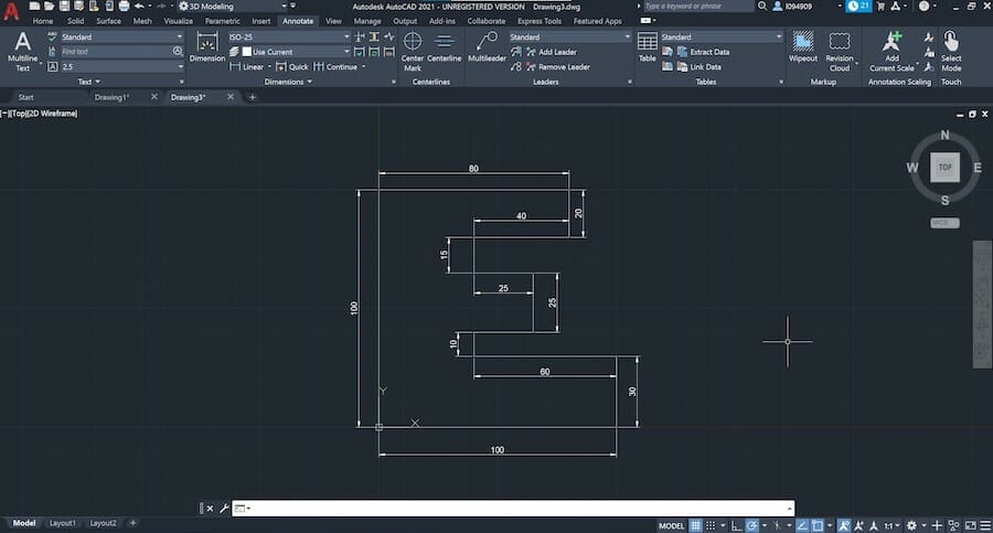
5.2: Adding Dimensions
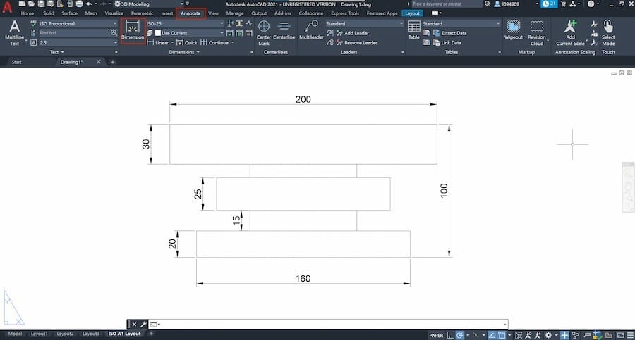
Dimensions are the most important piece of information in a technical drawing. Sometimes the number of dimensions can be quite overwhelming, so try to follow these three basic rules:
- Start with the smallest detail
- Annotate a detail only once
- Annotate every detail
Let’s add some dimensions to this drawing. First, switch to the “Annotate” tab on the Ribbon and select the “Dimension” command. This is a smart command which adapts to the feature you want to annotate.
Now click on either a line or two points to annotate its distance. You’ll then see the length or radius, and you can place the dimensions accordingly.
Position each annotation as to not intercept other lines or numbers and make sure it’s not too close to the view. For our model, it should look something like the above images.
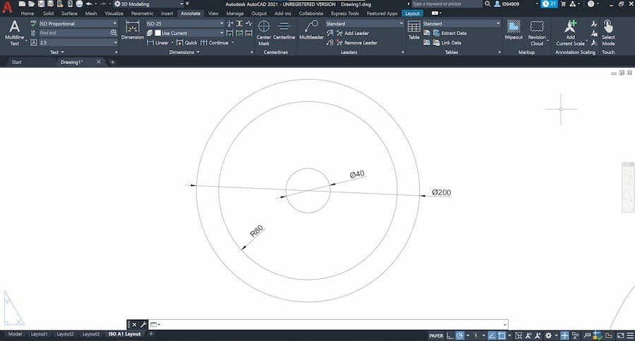
If you want to add dimensions to circles or holes, first hover the mouse over that feature. You can switch between radius and diameter by typing ‘R’ or ‘D’ on your keyboard.
5.3: Section View
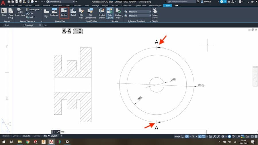
Section views are very common in technical drawings as they can show internal details and geometry that otherwise would be missed.
To create a section view, go to “Layout > Create View > Section View”. Select the view you want to create a section from followed by clicking on two points for the section line.
Confirm by pressing Enter and place the section view just like we did previously. You’ll see that AutoCAD will do all the hard work.
Step 6: Working with Meshes
Working with meshes is very important for those interested in 3D printing. If you want to 3D print or share your creations with other people, you’ll need to create or even edit a mesh file.
Formats like STL and OBJ are purely surface representations of a 3D geometry, and for this reason, CAD software like AutoCAD and others sometimes suffer from compatibility.
Generally speaking, AutoCAD can export to STL and OBJ just fine, but can’t natively import these formats. There are, however, a couple of ways to bypass this problem.
6.1: Importing STLs & Other Meshes
While not able to work natively with mesh files, AutoCAD handles other standardized formats like STEP and Autodesk’s interchange formats DWG and DXF.
There are plenty of options for converting meshes to such file formats. Perhaps the easiest is to use the online converter provided by CAD-Forum. We only need to upload the STL and the application will convert it to DWG or DXF.
Alternatively, you can use other CAD programs like Fusion 360 or free software like FreeCAD to do the conversion.
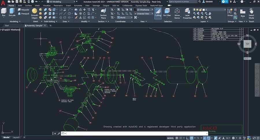
To open a DXF or DWG file in 3D mode, create a new project. Then go to the “AutoCAD logo > Open > Drawing” and select the file. When the model is imported, you can change the visual just like we did in step 3.
6.2: Exporting STL Files
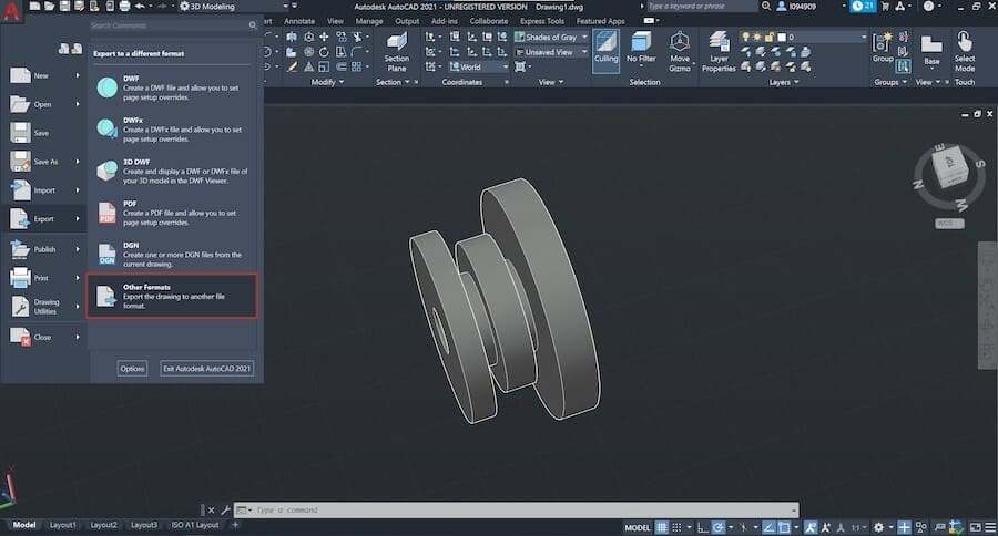
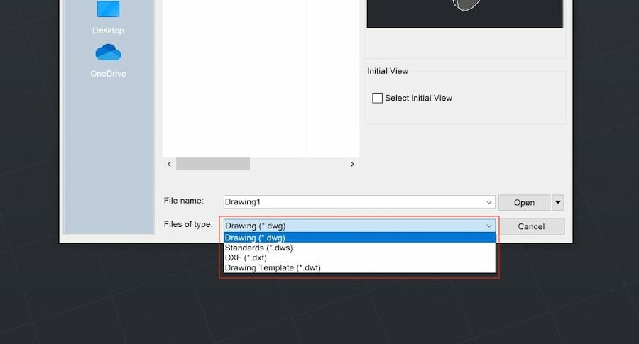
Luckily exporting STL files is very straightforward with AutoCAD.
Simply click on the “AutoCAD logo > Export > Other File Formats” and select “Lithography (*.stl)” as the file type in the file browser.
That’s it! Now you can 3D print your own models or even share them on online repositories like Thingiverse and MyMiniFactory.
Wrapping Up
This brings us to the end of our AutoCAD tutorial for beginners.
AutoCAD is a powerful CAD software with one of the best toolboxes and features to support 2D drawings. When it comes to 3D design, it’s still impressive, especially for 3D rendering.
However, as we’ve just experienced, it’s not an easy nor intuitive application. If you feel that AutoCAD isn’t the right tool for you, try checking other 3D modeling options like Tinkercad or SketchUp.
If the problem is cost, then check out other free alternatives to AutoCAD and keep on learning!
License: The text of "AutoCAD 2023 Tutorial for Beginners: 6 Steps to Success" by All3DP Pro is licensed under a Creative Commons Attribution 4.0 International License.
CERTAIN CONTENT THAT APPEARS ON THIS SITE COMES FROM AMAZON. THIS CONTENT IS PROVIDED ‘AS IS’ AND IS SUBJECT TO CHANGE OR REMOVAL AT ANY TIME.