How to Design 3D Printed Replacement Parts

When something breaks, you can model and 3D print replacement parts. Read on to learn how to design 3D printed parts!
Not all parts can be 3D printed. We like to say that we can make anything with 3D printing. While it’s true, our prints may not necessarily be functional. For example, if a broomstick breaks, you could print one. But it would take too much time, too much filament, and would still be very fragile compared to a wooden broomstick. In that case, going to the store and buying a replacement would have been a much better choice.
There are, however, parts that lend themselves well to 3D printing: a game controller, a side release buckle, a fridge handle, you name it. Whether you lose or break one, there’s no need to go to the store; you can just make a new one at home! This comes in handy especially for parts that are specific to a manufacturer, are hard to find commercially available, or are not sold individually.
You’ll probably want to avoid printing parts for heated applications or contexts that may pose safety hazards, like an oven. In such cases, just call a professional. But for just about everything else, it’s worth trying to design and print your own replacement parts. In this article, we’ll show you how!
Material Considerations
Before you start designing, it’s a good idea to consider the material you’ll use to creat your replacement part. You should consider this beforehand, as it can affect how you model your part.
If the part is already plastic, this is a little easier because the material you use doesn’t matter too much. The same goes for decorative items that aren’t functional. It gets trickier if the parts to be replicated are metallic or ceramic or if they have certain mechanical property requirements.
Here are the main 3D printing materials and what you should consider for each of them:
- ABS is great for parts that require high rigidity, high impact resistance, and don’t require too much flexibility or movement. Do take into account that ABS can contain additives or residue that are harmful to the environment, irritating to the skin, and toxic to consume. Therefore, it’s best to avoid it when possible and is an absolute no-go for food-related applications.
- PLA is the most common and affordable. It has good resistance to tension and compression but low bending resistance, so it’s not a great replacement for flexible parts. PLA is good for applications that require moderate strength. It doesn’t support impact or rotary loads, but dead weight is okay. Some brands are food safe. It’s the easiest material to print with. So, if you want to replace non-functional parts, this is the easiest option.
- PETG is generally food-friendly, as it’s derived from the same material used for plastic bottles. It has great impact resistance, and it’s the most flexible of the three. It can be complicated to work with due to stringing or bubbling issues, but it’s less prone to warping than ABS.
If you need materials with higher resistance than ABS or PETG, and this can’t be resolved with increased dimensions, you may want to consider high-performance materials, such as PC and PP.
- PC is short for polycarbonate. It produces semi-transparent prints, save for the noticeable layers. The material is flame resistant, an electrical insulator, and has a high toughness. It’s even used in the automotive industry during prototyping.
- PP stands for polypropylene, which is a polymer whose main advantage is high resistance to fatigue. Fatigue is a material’s tendency to break as a result of cyclic loading – for example, punching something many many times as opposed to just once. The material is water resistant and great for recycling, but it’s highly flammable and not recommended for use at high temperatures.

Model Replication
It seems only logical that to 3D print a part you would first have to have a model. If the part is common enough, you may get lucky and find it in a repository, in which case you don’t have to worry about the design at all. If it’s a spare part of a branded appliance, a 3D model may already exist, whether officially available from the brand or shared in repositories like GrabCAD.
But if this isn’t the case, you’ll first have to develop a model of the part that can be sliced and printed. There are two ways to do this: modeling the part based on measurements or 3D scanning the part.
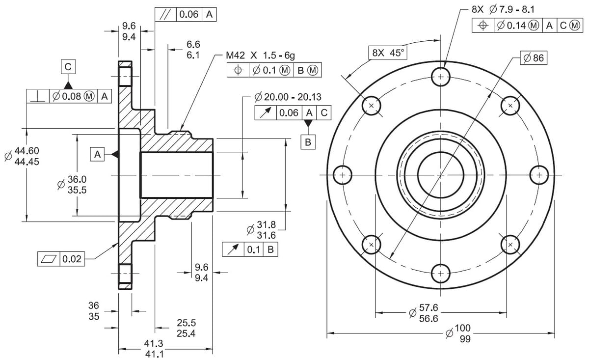
If your part has a simple enough geometry, you could measure the most important dimensions and model the part using parametric modeling software.
If the part has a very complex geometry, scanning may be an easier choice. Some examples where scanning could come in handy are parts that use surface modeling – which is found, for example, in many casing for objects like videogame controllers, consoles, cameras, and other electronics. Scanning is also useful if the part in question is a figurine.
Method 1: Modeling Based on Measurements
If you’re lucky enough to be replacing a simple part, modeling it yourself is probably the simplest solution. But before you can do that, you’ll need some reliable and useful measurements. The following are some helpful tricks:
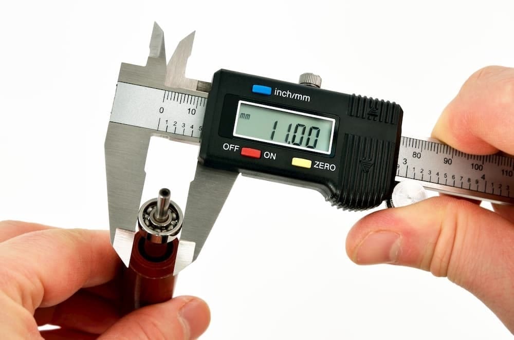
- A vernier caliper is the best tool to measure objects of up to 15 cm. They use metric units and include scales, allowing for a precision of up to 0.5 mm. They’re made to accurately measure outside, inside, and depth distances.
- Don’t measure imprecise lengths. For example, don’t measure the radius of a circle, as you can’t know where exactly the center is. It’s better to measure the diameter.
- Only essential measurements need to be preserved. Small features – for example, to improve gripping – don’t need to be exact replicas as long as your version of them in the replacement model still accomplishes the same functionality and doesn’t get in the way.
- For many parts that were initially part of mechanical household appliances, you may be able to find the exact measurements online. You’ll need to know the brand and a serial or some other reference number for the appliance.
Method 2: Scanning
For more complex parts with advanced geometries, modeling it yourself may be beyond your ability. For example, surface modeling usually uses NURBS objects, which are generally considered a separate branch of modeling. It’s probably best to bypass this process and scan the part.
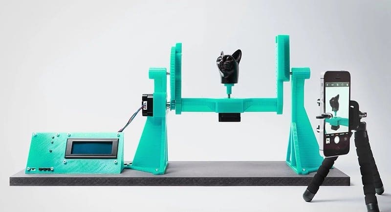
Scanning is a smart solution with limited effort. You’ll just need a scanner and the part. Hopefully, the part is still in a good enough state to scan. If not, you might have to phone a friend and borrow one from them temporarily.
The process is fairly simple but varies a bit depending on the hardware and software you’re using. There’s a wide range of options including mobile phone apps and handheld scanners. Some have even used old Kinect devices.
Regardless of which option you choose, the following are some things to take into account:
- If the object you need to replace is transparent, most scanners won’t work.
- If you need high precision for small details, a high-quality scanner will be necessary.
- After scanning an object, you usually need to clean up the result. Thankfully, free programs like Blender are good enough for the task.

Model Details
Once you have your base model, it’s time to refine it. You could print it right off the bat with just the base measurements, but some improvements wouldn’t hurt. Sometimes, they may even be necessary. In this article, we focus on two refinements:
- Improvements: Consider what made the part fail in the first place and take this opportunity to solve it so that you don’t have to print new ones every week. Of course, if the original part simply got lost, this step may well not be necessary.
- Tolerances: If the model needs to fit some part inside it or fit inside another part, you have to consider your printer’s ability to achieve the exact dimension required to keep the part functional.
Improvements
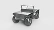
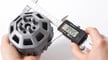
When designing a spare part, you can also add improvements to avoid future failures and avoid printing more of these spare parts in the future. Let’s take the image above as an example. It’s a tent corner piece that was designed and printed for someone whose commercial tent corners broke.
This design was constructed with the surviving corner pieces and based a set of requirements that included improved resistance. The thickness of the pole guides was increased, but the inner diameter stayed the same, as poles need to screw into it. Additionally, to reduce the chance of the corners snapping due to the force of the tent poles, nerves were added to take on some of that bending momentum.
These design improvements were minute but may go a long way to prolong the lifespan of the replacement part. As you’re designing your part, consider what sort of improvements may be beneficial to your use case.
Tolerance
There are a couple of different ways to talk about tolerance, so for clarity’s sake let’s define it. According to Wikipedia, tolerance is “the permissible limit or limits of variation in a physical dimension.” If we say we want a diameter that’s 5mm ±0.5, we’re saying that we want it to be ideally 5 mm, but it’s still fine if it comes out measuring 5.5 or 4.5 mm.
3D printers’ tolerance, however, refers to how accurate the printer is with regard to achieving certain dimensions. For example, you define a dimension of 3 mm in a modeling program, but when you print and measure the part, it comes to measure 3.2 mm. That means your printer has a tolerance of +0.2 mm.
Essentially, you learn your printer’s tolerance based on experience. Print settings can affect it, as does poor calibration. A printer’s tolerance can change if the printer needs maintenance that impacts its accuracy. It’s a good idea to calibrate your printer if you’re noticing discrepancies between the specifications of your model and the printed part.
Design Tolerance
When designing a replacement part, both types of tolerance are relevant. Design tolerance refers to the acceptable dimensions of the design. If the printed part came out measuring 3.2 mm in length, it may or may not be acceptable depending on whether it needs to fit somewhere.
Say the part needs to be 3 mm. Knowing your printer’s tolerance, you may need to design the part to be a bit smaller. Given the printer’s +0.2-mm tolerance, you can design the part to be 2.8 mm.
A replacement for a broken vase? The exact dimensions don’t matter too much. But if you need a replacement for a remote control battery cover, the wrong dimensions will render it useless.
General Rules
If the part goes inside something…
- and you need a tight fit, the tolerance should make it a bit bigger.
- and it needs a loose fit, the tolerance should make it a bit smaller.
- and you need a perfect slip-fit, the tolerance should be more controlled and reduced but tending toward being smaller, as friction is not desired.
If something goes inside of the part…
- and you need a tight fit, the tolerance should make it a bit smaller.
- and you need a loose fit, the tolerance should make it a bit bigger.
- and you need a perfect slip-fit, the tolerance should be more controlled and reduced but tending toward being bigger, as friction is not desired.
Printing Details
As the design may have to comply with specific requirements, it may not be so easy to simply print it willy-nilly. Print settings could play an important role. Therefore, it’s important to consider the following:
- Slicing orientation
- Settings that lend strength to a part, including strong infills
- Settings that are appropriate for parts that need some flexibility
- Settings that may impact the dimensional accuracy of a part
In some cases, we have complete articles talking about these subjects, but we’ll give you the SparkNotes versions of each.
Slicing Orientation
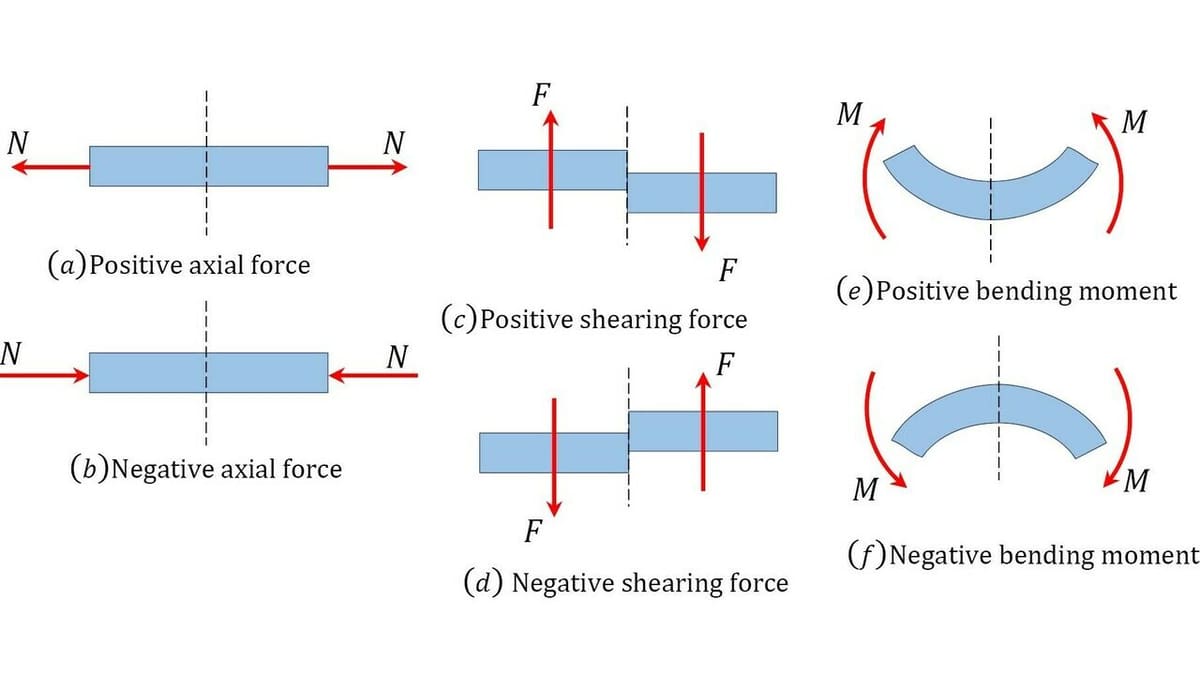
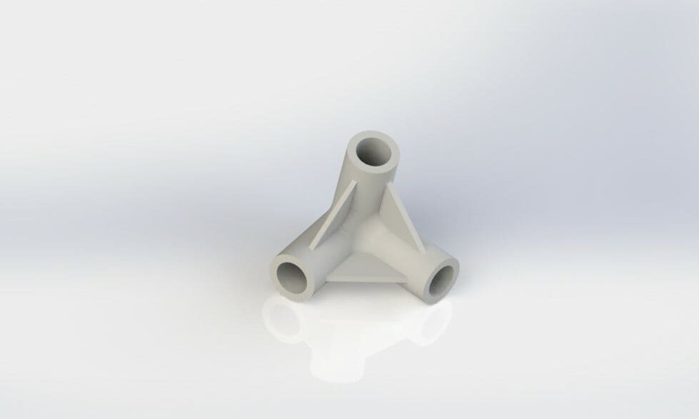
This is relatively complex, but you don’t need to know all the inner workings to be able to use it to your advantage. A 3D-printed part is anisotropic. This means that the material properties aren’t the same in every direction. This is because the print doesn’t have the same structure throughout. Therefore, the orientation of the print’s fibers actually affects its mechanical properties.
Looking at the image above, you can imagine that axial loads won’t damage the print as much as shear force, since axial forces are parallel to the direction of the printing fibers. On the other hand, bending stresses will be very dependent on the density of the infill and the number of shell lines.
Usually, we only consider the orientation to avoid support, but in this case, mechanical performance may also need to be taken into account to increase your part’s lifespan. If you know your part is going to have to withstand some loads, try to design it so that the direction of force will be parallel to the layer lines and infill pattern.
Strength
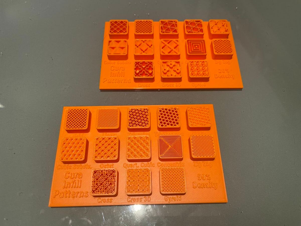
Generally speaking, higher infill densities and thicker perimeters provide more strength. Moreover, the infill pattern may affect the strength of the part. A part with 20% zig-zag infill will show a different strength than a part printed with 20% gyroid infill even though they technically have the same density.
In reality, the density slightly varies due to the geometry of the infill, and the load is distributed differently across its structures. For example, with triangular infill patterns, it can be assumed that stresses will concentrate on corners, which aren’t present in a gyroid pattern.
That said, when testing the strength of different infill patterns, it was found that a zig-zag (also known as rectilinear) infill pattern is comparable in strength to a grid. Zig-zag lines invert from one layer to another, which can be beneficial to dissipate stress concentration and prevent breaking in the X- and Y- directions. Similarly, honeycomb, triangles, and gyroid infill patterns may be best for compressive strength due to their ability to evenly distribute stress in all directions.
One interesting thing about the gyroid pattern is its uniform strength. For most other infill patterns, their strength is heavily dependent on the direction of applied stress. A gyroid pattern, however, was found to have the same strength on all three axes.
Flexibilty
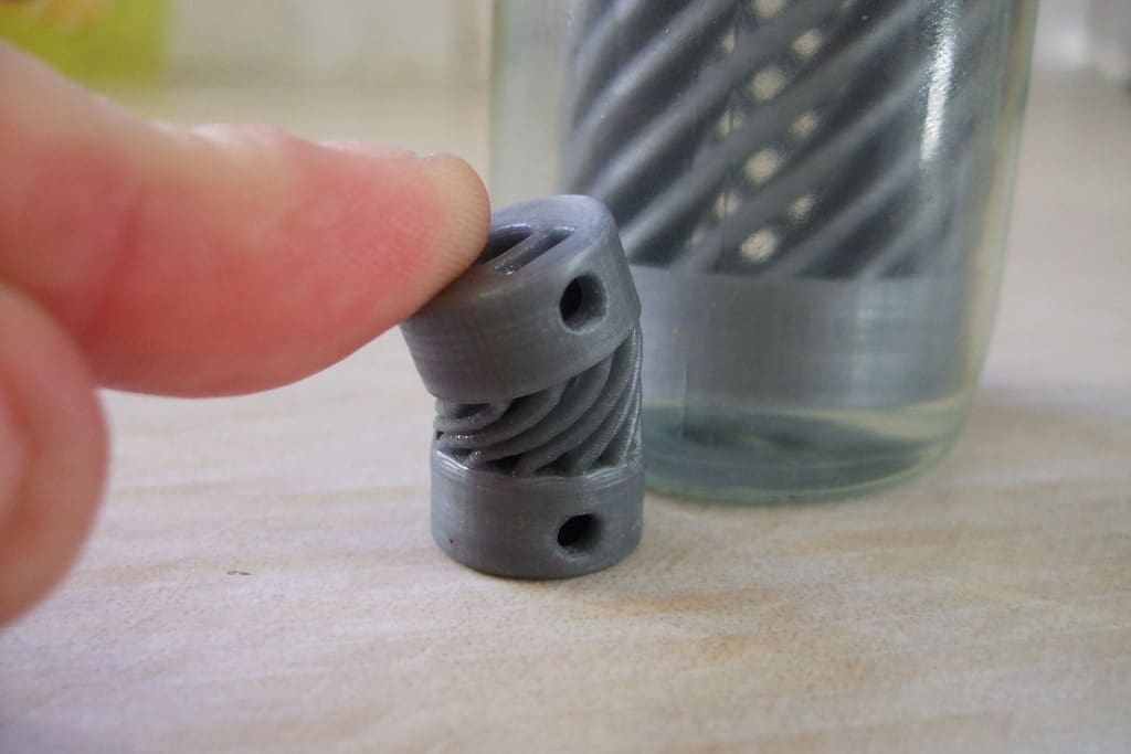
A big factor when it comes to prints that require some flexibility is the material. The material should be able to bend (or deform) without breaking and returning completely to its original position.
There are also many print settings that are important to ensure prints take advantage of the flexibility of the material. For example, having a low infill percentage in the bending area of the part is not desirable because this will cause inner strain in the object when it’s deformed. It’s much better for flexible parts to deform “as a unit”, so to speak.
If you can do multi-processes in your slicing software, you can use this to your advantage by reducing the infill percentage of rigid area of parts and increasing the percentage of bending area of the parts.
Additionally, flexible prints also benefit from having a small layer height, as this will cause the layers to be better attached together, increasing likelihood that the layers bend together.
Dimensional Accuracy
Dimensional accuracy can also be effected by the print material, as some materials are more troublesome to print with than others. Like we mentioned beforehand, your printer’s maintenance can affect the dimensional accuracy, as poor lubrication or dust can alter the original tolerance the printer had. In your slicer software, you can take into account expected shrinkage to improve the dimensional accuracy of the print.
License: The text of "How to Design 3D Printed Replacement Parts" by All3DP is licensed under a Creative Commons Attribution 4.0 International License.