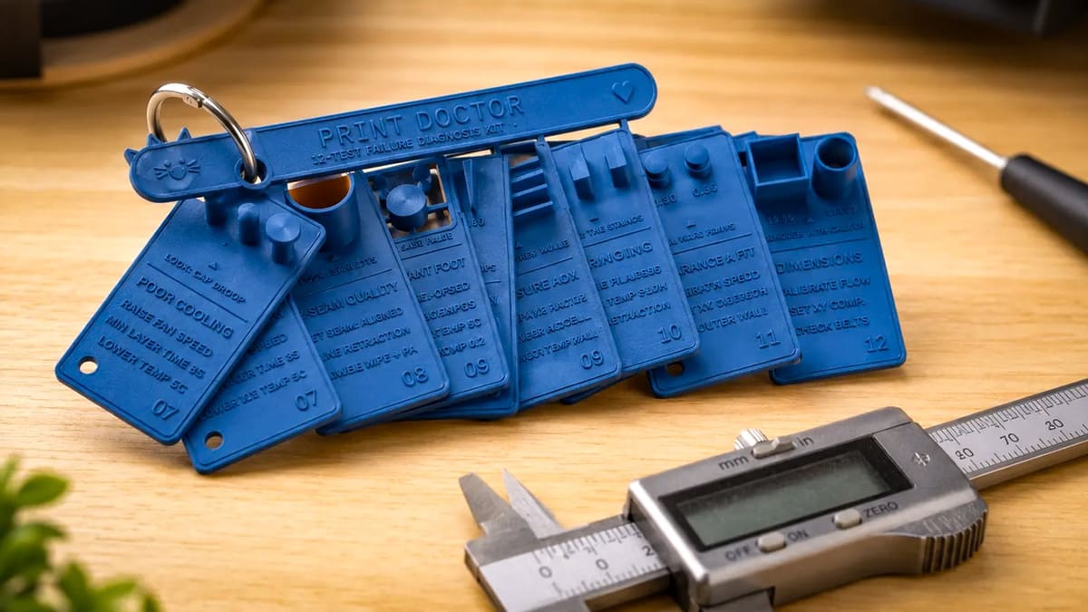
18 Free 3D Print Test Models, Plus How to Fix Everything from Stringy Prints to Bad First Layers

These free calibration models help you diagnose a wide range of 3D printing problems and choose the right setting to fix them.
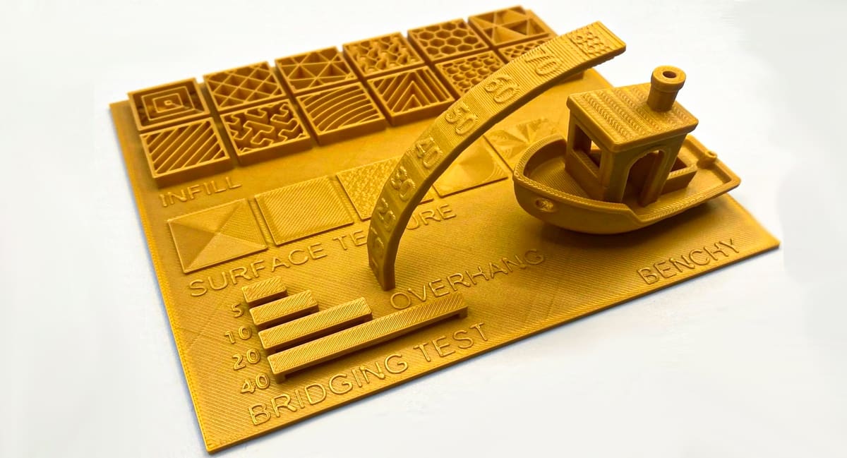
The best 3D printer test print isn’t necessarily the most difficult or impressive model. It’s the one that answers the question you’re currently asking, such as “Why won’t my first layer stick to the build plate?” or “Why are the moving parts in my print-in-place model fused together?”
A 3D printer test print can save hours of failed printing or it can send you down an unproductive rabbit hole. The difference is knowing which model to test and what the model actually is intended to reveal.
A Benchy, for example can reveal several symptoms at once, but it usually can’t tell you which single setting caused the problem. A calibration cube may expose dimensional error, but that doesn’t mean you should immediately change the steps per millimeter for your X, Y, or Z axes.
In this guide, we’ve separated focused calibration models from general benchmarking models and torture tests, which push your print settings to the limit. We’ll show you which test to choose, what a good result looks like, and, most importantly, what to change next.
This guide is intended for filament-based FDM printers, of course. Resin printers require different calibration models and procedures.
One Test, One Question
Diagnosing a print problem is different than tuning and general calibration.
So when you face a specific defect in your printed parts, first use a specific problem-diagnosing model, then print a general calibration model like a Benchy, dragon, cat, or toaster. At that point, you have confirmation that the printer, filament, slicer, and settings are working together.
Calibration test, diagnostic print, and torture test are terms are often used interchangeably, but they describe different jobs.
A calibration test varies or measures a defined parameter, a diagnostic print reveals a symptom, and a benchmark or torture test combines multiple difficult features in one model. Benchmark prints are useful for comparing profiles, materials, printers, or changes made over time. However, because several variables affect the result, they are usually poor tools for isolating one setting.
When a broad test fails, use the visible symptom to select a more focused test rather than changing several settings at once.
Which Test Print Do You Need?
Before You Print Anything
A test model is only as useful as the way it is prepared. Download the STL or 3MF file and slice it using a suitable profile for your printer, nozzle, bed, and material. If any of those four components are misrepresented in your slicing software, it will throw off your results.
Be cautious with pre-sliced G-code from an unknown source. G-code contains printer commands, and an incompatible file can use incorrect temperatures, movements, dimensions, or machine-specific instructions.
Since a test print cannot compensate for a loose hot end, partially blocked nozzle, damaged extruder, oily build plate, or incorrectly assembled motion system, do a thorough printer inspection first.
Before beginning:
- Inspect the printer for loose belts, wheels, screws, connectors, and damaged parts.
- Start with a reputable printer and filament profile.
- Clean the build surface according to its manufacturer’s instructions.
- Make sure the nozzle is clean and correctly installed.
- Use dry filament if moisture may be contributing to stringing, popping, or an uneven surface.
- Keep the printer, nozzle, filament, layer height, and cooling settings consistent while comparing results.
- Change one relevant parameter at a time.
The Best Focused Calibration Tests
First-Layer Patch
- Best for: Poor adhesion, uneven first layers, gaps between lines, and an overly squashed first layer
- Not suitable for: Diagnosing every adhesion problem
- Changes settings during printing: No
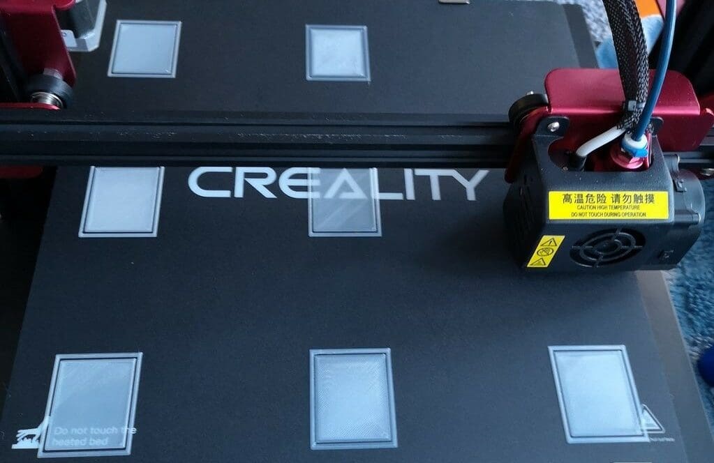
Almost every print depends on a reliable first layer, which makes a simple single-layer patch one of the most valuable tests you can run.
Use your printer’s built-in first-layer calibration where available. Otherwise, slice a large square, several smaller patches distributed around the bed, or a parametric bed-leveling model. The pattern should be only one layer high and cover enough of the build surface to reveal local variation.
On a good first layer, neighboring lines should touch and form a consistent surface without pronounced ridges. The filament should remain attached when the nozzle changes direction.
If the nozzle is too high, the lines may appear rounded, separated, or easy to pull away. If it is too low, the nozzle may scrape the surface, produce translucent or rough areas, push material into ridges, or restrict extrusion.
Adjust the printer’s Z offset or first-layer calibration in small steps. If one area is correct while another is not, investigate bed tramming, mesh calibration, gantry alignment, or build-plate flatness instead of applying one global Z-offset change.
A correct-looking first layer does not rule out contamination, under-extrusion, or unsuitable material settings. Prusa notes that adhesion can still fail because of a dirty sheet, print settings, leveling, or under-extrusion even when the first-layer height appears correct.
Use your printer’s built-in calibration, a slicer-generated patch, or the existing parametric bed-leveling model.
What to change: Lower the Z offset if first-layer lines are rounded, separated, or peel away; raise it if the nozzle scrapes or creates ridges. If the problem varies across the bed, re-tram the bed or rerun mesh leveling. If adhesion is still poor with a good-looking first layer, clean the build plate and check first-layer temperature, speed, and extrusion.
This model below helps you see how to improve your first layer to produce the best prints.
- Who designed it? pgreenland
- Where to find it? Thingiverse
Temperature Tower
- Best for: Selecting a nozzle temperature for a particular filament
- Not suitable for: Fixing every form of stringing or poor layer adhesion
- Changes settings during printing: Yes
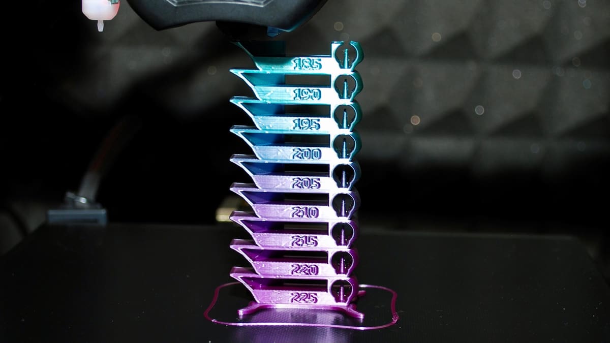
A temperature tower is divided into labeled sections, with each section printed at a different nozzle temperature. It can reveal how temperature affects bridging, overhangs, stringing, surface finish, fine details, and layer bonding.
The critical detail is that the temperature must actually change during the print. Printing a tower-shaped STL at one constant temperature does not produce a temperature test.
OrcaSlicer can generate a temperature tower automatically. In other slicers, you may need to insert temperature commands at the correct layers or use another built-in calibration workflow. PrusaSlicer, for example, supports custom G-code at selected layers, including the M104 command used to change hot-end temperature.
Inspect every section rather than choosing whichever one looks shiniest. Look for:
- Clean bridges and overhangs
- Crisp text and corners
- Minimal stringing
- Consistent extrusion
- Adequate layer adhesion
- No obvious discoloration or overheating
The visually cleanest section may not provide the strongest layer bonding. For functional parts, test layer adhesion separately before settling on an unusually low temperature.
Save the chosen value in a filament-specific profile. Different colors and formulations sold under the same material label can behave differently. Note that poor bridging can occur at both ends.
Generate the test from OrcaSlicer or use a verified temperature-tower model with correctly configured layer changes like the model below.
This model tests overhangs, bridges, stringing, and even your printer’s ability to print curvy shapes. Of course, it’s also a great way to quickly calibrate your printer’s temperature for a particular material.
For deeper dives, you can check out our guides on using a temp tower in Cura and in PrusaSlicer.
- Who designed it? gaaZolee
- Where to find it? Thingiverse

Maximum Volumetric-Flow Test
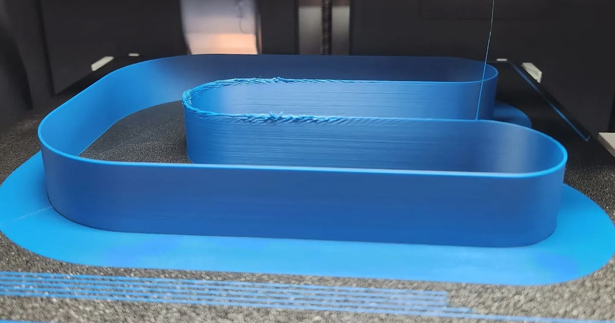
- Best for: Finding how much filament a hot end and material can melt reliably
- Not suitable for: Setting ordinary travel speed or acceleration
- Changes settings during printing: Yes
Maximum volumetric flow describes how much plastic the printer can melt and extrude per second, normally expressed in cubic millimeters per second.
This matters because a speed entered in millimeters per second does not tell the whole story. A wide, tall extrusion requires more material than a narrow, thin one at the same movement speed. When the requested flow exceeds what the hot end can melt, the print may become thin, rough, matte, inconsistent, or weak.
A maximum-flow test gradually increases the requested flow as the model rises. Inspect the print for the first point where surface quality or extrusion becomes inconsistent. OrcaSlicer’s calibration guide recommends identifying the failure height, determining the corresponding flow, and applying a conservative margin.
The result belongs in the filament profile rather than being treated as a universal printer limit. Material, color, temperature, nozzle, hot end, and filament condition can all affect it.
Maximum volumetric speed acts as a limiter: It can reduce the requested print speed when the corresponding extrusion would exceed the configured flow limit, but it does not make a print faster by itself.
What to change: Set the filament profile’s maximum volumetric flow slightly below the point where extrusion becomes rough, thin, or inconsistent. If failure occurs unusually early, check nozzle temperature, clogs, extruder grip, spool resistance, and filament condition before lowering the limit.
Where to find it: OrcaSlicer’s Calibration menu includes a maximum volumetric-speed test or try this model below.
- Who designed it? Grzdacz
- Where to find it? Printables
Pressure Advance or Linear Advance Test
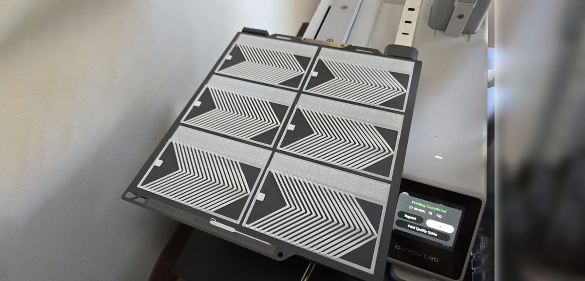
- Best for: Bulging corners, thin areas near corners, and inconsistent extrusion during speed changes
- Not suitable for: Printers whose firmware does not support the feature
- Changes settings during printing: Yes
Filament does not respond instantly when the print head accelerates or slows down. Pressure builds inside the nozzle, particularly during faster printing, and can leave excess material at corners or too little material immediately before or after them.
Pressure advance—called linear advance in Marlin—compensates for this behavior.
The best test depends on the printer and firmware. OrcaSlicer provides several pressure-advance calibration methods. Klipper offers a tuning tower that increases the pressure-advance value as the print rises, while Marlin provides a K-factor line-pattern generator.
For a tower, select the cleanest region, calculate the corresponding value according to the test instructions, and save it in the appropriate printer or filament profile.
Pressure advance can depend on the filament, temperature, extrusion system, and print conditions. Recheck retraction afterward because correctly tuned pressure control can reduce the amount of retraction required. Marlin’s documentation specifically recommends recalibrating retraction after linear advance.
What to change: Increase pressure advance if corners bulge or excess material accumulates during direction changes. Decrease it if corners become rounded, gaps appear, or extrusion thins near corners. Save the cleanest-tested value in the appropriate filament or printer profile, then recheck retraction.
Do not enable a value copied from another printer without testing it.
Where to find it: Use OrcaSlicer’s built-in calibration, Klipper’s official pressure-advance procedure, or Marlin’s K-factor generator, or try this model below.
- Who designed it? Wigiwagons
- Where to find it? MakerWorld
Flow-Ratio Test
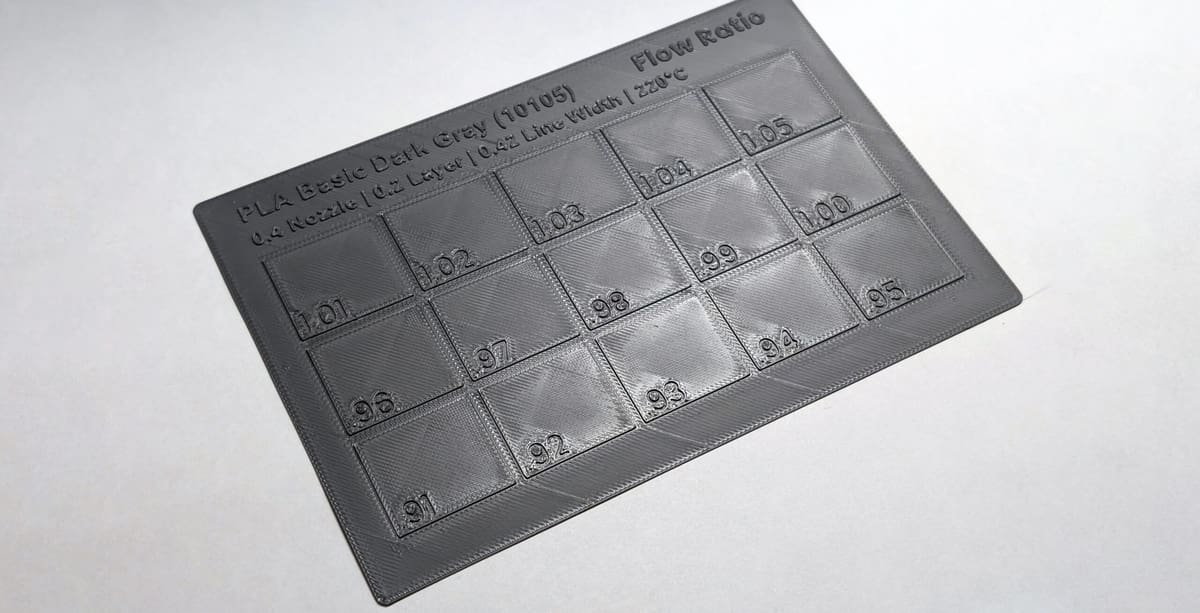
- Best for: Fine-tuning filament-specific extrusion
- Not suitable for: Calibrating the extruder motor’s movement
- Changes settings during printing: Yes, depending on the method
Flow ratio—also called extrusion multiplier, with related controls named “flow” in some slicers—adjusts how much material the slicer requests.
It is not the same as E-steps or Klipper’s extruder rotation_distance. Those describe the mechanical relationship between the extruder motor and filament movement. Flow ratio belongs in the filament or slicer profile and compensates for how a particular material prints.
OrcaSlicer’s built-in flow test generates several samples with different flow modifiers. Compare the top surfaces and choose the range where the lines meet cleanly without visible gaps or raised ridges. The current OrcaSlicer workflow uses multiple passes to narrow the result.
What to change: Increase the flow ratio if top-surface lines remain separated or walls print thin. Decrease it if lines pile up into ridges, surfaces look rough, or dimensions become oversized. Save the best value in the filament profile rather than changing the extruder’s mechanical calibration.
Do not use flow ratio to conceal a partially blocked nozzle, slipping extruder, incorrect filament diameter, or badly configured extruder movement.
For printers that expose extruder calibration, verify the mechanical extrusion setting using a measured filament movement rather than a printed staircase or cube. Klipper’s documented procedure commands a known extrusion distance and measures the filament directly.
Where to find it: OrcaSlicer includes a built-in flow-ratio calibration or try this model (pictured above) by QuantifyDeisgn via MakerWorld.
Retraction Tower
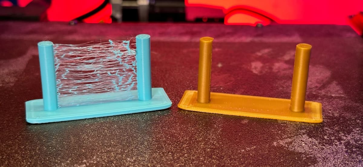
- Best for: Fine strings between separate features
- Not suitable for: Stringing caused primarily by wet filament, excessive temperature, or a leaking hot end
- Changes settings during printing: Yes
Retraction pulls filament back before the nozzle travels across an open space. A retraction tower changes the retraction value as it rises, allowing you to compare several values in one print.
OrcaSlicer can generate this test automatically. Its documentation recommends selecting the shortest retraction length that produces a clean result rather than using more retraction than necessary.
Start only after selecting a reasonable nozzle temperature and tuning pressure advance and flow. Otherwise, a retraction adjustment may be compensating for a different problem.
Inspect the strings between the towers:
- Thick strands can indicate insufficient retraction or excessive temperature.
- Fine, inconsistent hairs can also come from damp filament.
- Gaps after travel moves can indicate excessive retraction or an unsuitable restart behavior.
- Clicking or grinding from the extruder can indicate an overly aggressive retraction distance or speed.
What to change: Increase retraction if clean, dry filament still leaves strings between separate features. Decrease it if gaps appear after travel moves or the extruder clicks or grinds. If stringing persists across the test, check nozzle temperature, filament moisture, and nozzle condition before increasing retraction further.
Retraction requirements vary considerably between direct-drive and Bowden systems. Use a test range appropriate to the printer rather than copying a generic value.
Stringing can also result from material left on the nozzle, unsuitable temperature, or incorrect retraction settings. Z lift or Z hop is not a universal stringing fix; lowering it may improve stringing, while disabling it can allow the nozzle to strike the print.
Where to find it: Generate a retraction tower through OrcaSlicer or another slicer with a parameter-changing calibration function or try the model pictured above.
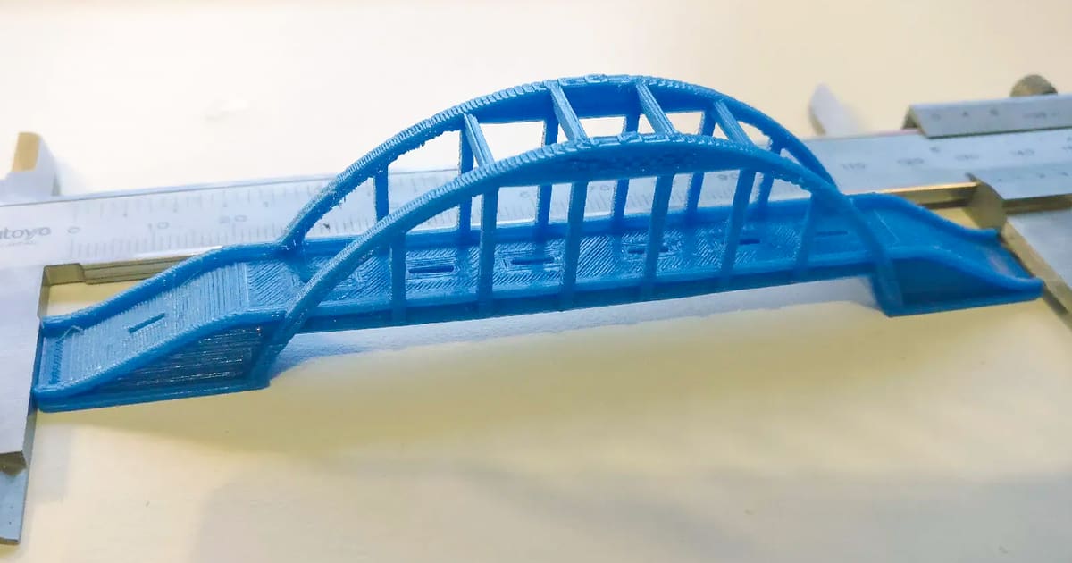
Bridge Test
- Best for: Sagging horizontal spans between two supported points
- Not suitable for: General overhang calibration
- Changes settings during printing: No, unless deliberately configured as a tower
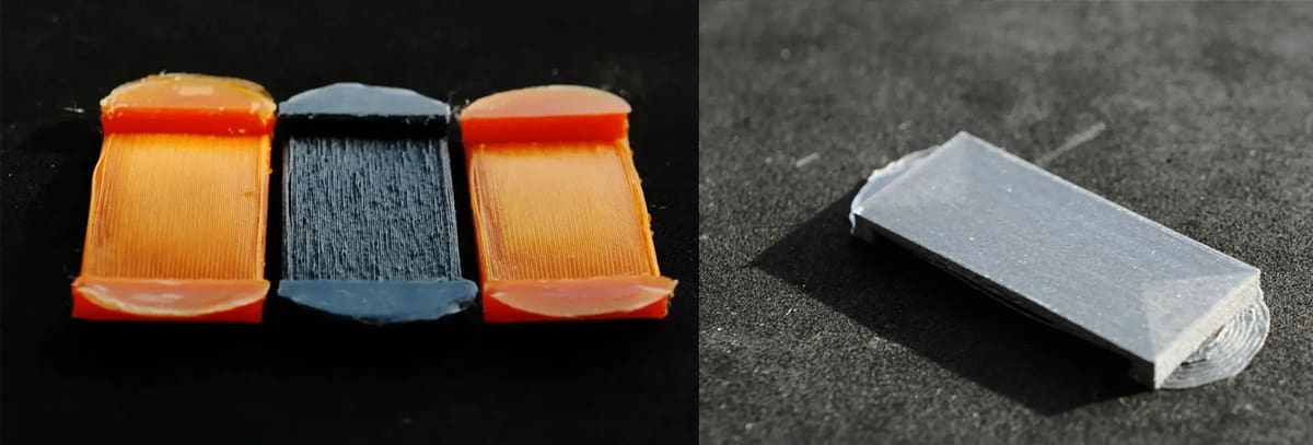
Bridges are extruded across empty space between two supported points. A dedicated bridge model uses several span lengths to show where a profile’s cooling and extrusion settings begin to struggle.
Start with the printer or slicer manufacturer’s recommended bridge settings. Then inspect the underside and side profile of each span.
A good bridge should remain reasonably flat, with separate extrusion lines forming a continuous surface. A failed bridge may sag, break into loose strands, curl upward at its anchors, or pull neighboring features out of position.
What to change: Improve part cooling, lower nozzle temperature, or reduce overhang speed if undersides are rough or edges curl. If one side consistently prints worse, inspect the fan duct and airflow. For overhangs that still exceed the printer’s practical limit, reduce layer height, reorient the model, or use supports.
Do not judge bridge quality from the top surface alone. The underside usually shows the failure more clearly.
Materials behave differently. Settings that produce crisp PLA bridges may result in weak layer bonding or warping with another polymer.
Where to find it: Use a compact bridge model with several clearly labeled span lengths like this model pictured above.

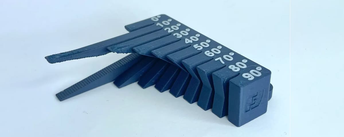
Overhang and Cooling Test
- Best for: Rough undersides, curling edges, and determining a practical unsupported angle
- Not suitable for: Testing bridges, which are supported at both ends
- Changes settings during printing: Usually no
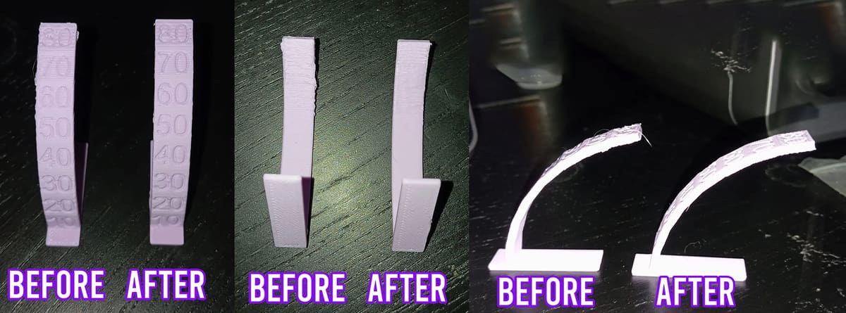
An overhang extends outward from the previous layer without support directly beneath its outer edge. The farther each layer projects, the less material it has underneath it.
A useful overhang test presents a series of labeled angles. Inspect the underside, edges, and dimensional shape of every section.
Do not treat the largest angle that technically finishes as the printer’s recommended limit. The practical limit is the steepest section that still provides acceptable quality for the intended part.
What to change:
- Increase cooling fan speed or add a duct/shroud — the biggest lever for rough or curling undersides
- Still poor with cooling maxed? Lower nozzle temperature slightly or slow down overhangs and outer walls
- Shallow, persistently rough slopes: reduce layer height
- One side worse than the other: check for uneven airflow before changing settings
- Beyond the printer’s practical angle limit: reorient the model or add supports rather than tweaking further
Check the cooling fan and duct before changing the profile. If one side of the model consistently looks worse, uneven airflow may be contributing to the problem.
Where to find it: Use a compact test with clearly labeled overhang angles and no supports like this free model pictured above.
Clearance Tolerance Test
- Best for: Print-in-place mechanisms, fitted assemblies, and practical part clearance
- Not suitable for: Calibrating the X, Y, or Z motor steps
- Changes settings during printing: No
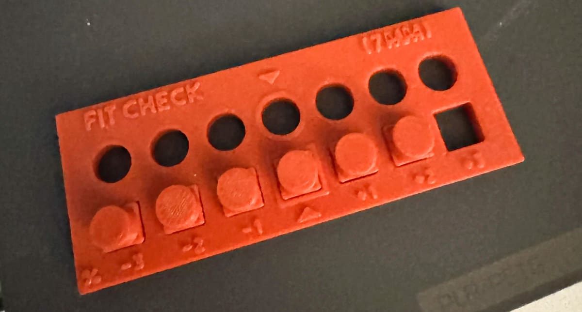
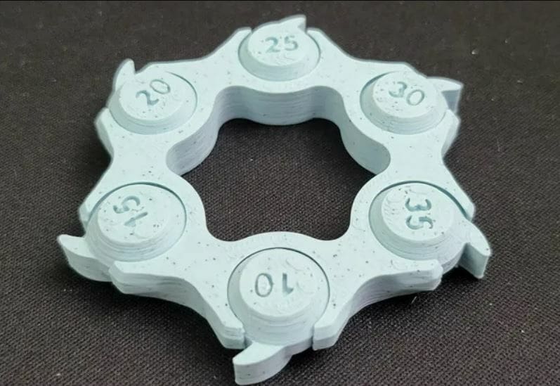
Tolerances are a critical aspect of functional 3D prints. Adjusting them can be tricky and time-consuming. According to comments from users, this clearance tolerance test is small and fast to print. That way, it will save you time.
Two parts can be dimensionally close to their CAD values and still fuse together when printed with insufficient clearance. A tolerance test provides moving pins, gaps, or mating parts separated by known distances.
The Clearance Tolerance Test by 3DMakerNoob is a compact option inspired by larger tolerance tests. It lets you identify the smallest clearance at which the printed parts can move freely.
Allow the print to cool before judging it. Gently test each section without forcing the smallest gaps, as excessive pressure can make a fused feature appear successful.
Record the smallest reliably moving clearance, not merely the section that can be broken free with tools. Use that value as a design reference for the same printer, nozzle, material, orientation, and profile.
What to change: If clearances are too tight, first check flow and first-layer elephant foot, then consider pressure advance, cooling, seam placement, and XY or hole compensation. If the print is otherwise accurate, use the smallest reliably moving clearance as a design allowance rather than changing motor steps.
The result is not universal. A clearance that works in PLA may fail with PETG, ABS, a larger nozzle, or a different orientation.
- Who designed it? 3DMakerNoob
- Where to find it? Printables
Ringing and Input-Shaping Test
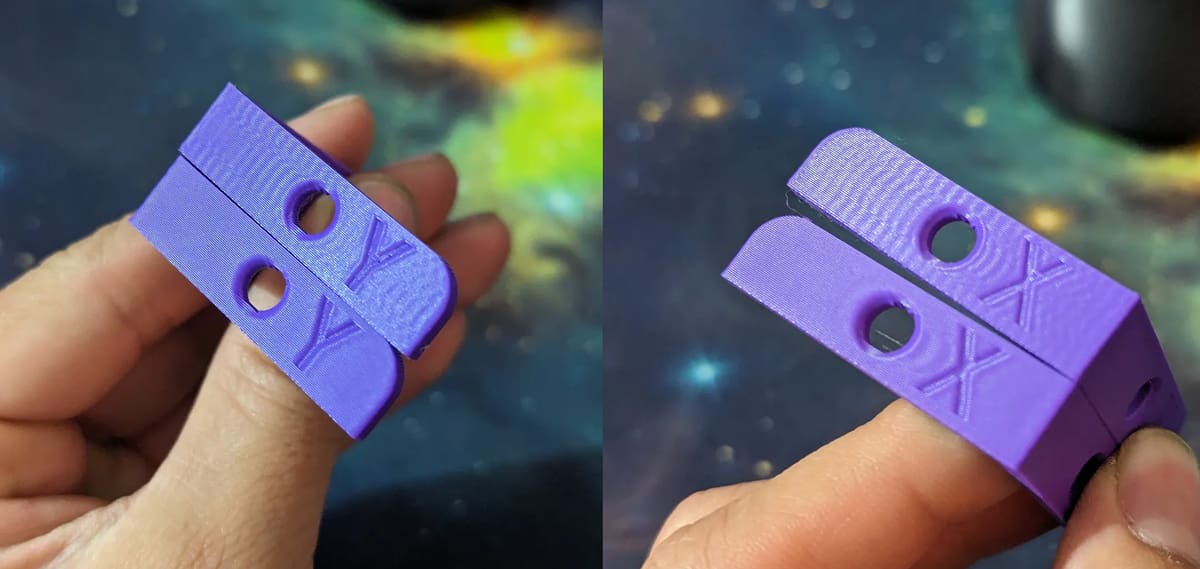
- Best for: Repeated waves or echoes after sharp corners
- Not suitable for: Random surface roughness or inconsistent extrusion
- Changes settings during printing: Usually yes
Ringing—also called ghosting—appears as repeated waves after a sudden direction change. It can be caused or amplified by vibration, loose mechanical parts, high acceleration, flexible frames, or the moving mass of the toolhead or bed.
Before tuning software compensation, inspect the mechanics. Check belt condition and tension, pulleys, frame fasteners, wheels or linear rails, toolhead mounting, and anything recently added to the moving assembly.
The correct calibration procedure depends on the firmware. Klipper provides a ringing test model and a manual procedure for estimating resonance frequency. It also supports accelerometer-assisted tuning on compatible hardware. Marlin provides its own input-shaping calibration patterns and instructions.
A genuine ringing pattern should repeat after a sharp feature with reasonably consistent spacing. Klipper notes that a defect that does not follow the test model’s corner pattern may have a different mechanical or extrusion-related cause.
What to change: Tighten or repair loose mechanical parts before tuning software. If the mechanics are sound, reduce acceleration or calibrate input shaping using the printer’s firmware-specific procedure. Retest after any change that affects moving mass, belt tension, or frame stiffness.
Retest after making changes that affect moving mass or stiffness, such as replacing the toolhead, changing the bed, adding a glass plate, tightening belts, or installing a new fan duct.
Where to find it: Use the official procedure for the printer’s firmware or try the model pictured above.
XYZ Calibration Cube
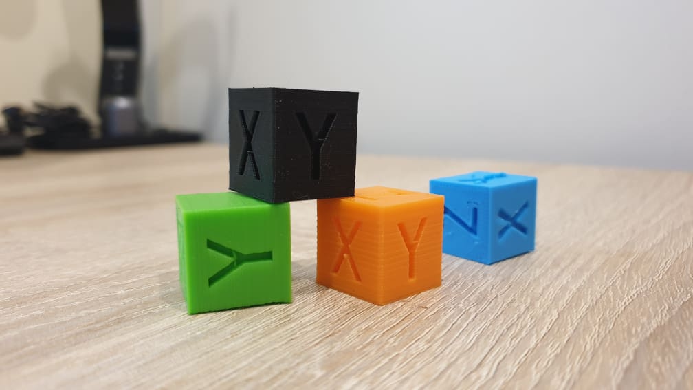
- Best for: A quick dimensional and surface-finish check
- Not suitable for: Directly recalibrating X-, Y-, or Z-axis steps from one printed measurement
- Changes settings during printing: No
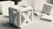
The XYZ calibration cube is small, fast, and easy to compare across profile changes. Its labeled faces also make it simple to identify the orientation of a defect.
Measure the cube only after it has cooled. Take several measurements away from the first few layers and avoid pressing the caliper jaws into the plastic. Examine more than the headline dimensions:
- Is the bottom wider because of elephant foot?
- Are the vertical walls bowed?
- Are the X and Y dimensions different?
- Are the corners swollen?
- Is the top surface over- or under-extruded?
- Are the letters crisp?
- Do repeated waves appear after the letters or corners?
Do not immediately adjust the X, Y, or Z steps per millimeter to make one printed cube match its nominal size. Klipper’s documentation explicitly advises against a “measure and trim” method for those axes, explaining that axis movement should instead be derived from the belts, pulleys, lead screws, and printer hardware.
Printed dimensions are also affected by first-layer squish, extrusion width, flow, shrinkage, skew, cooling, and measurement technique. Address those causes before considering machine-specific dimensional compensation.
Use a longer dimensional test or a part with separated measurement features when high accuracy matters. A small error or measurement inconsistency represents a large percentage of a 20-mm cube.
What to change: Match the adjustment to the defect: correct Z offset or elephant-foot compensation for a widened base, flow for over- or under-extruded surfaces, pressure advance for swollen corners, and mechanical or input-shaping settings for ringing. If X and Y dimensions differ consistently, check skew, belts, pulleys, and dimensional compensation rather than changing axis steps from a single cube.
This calibration cube is a simple, fast, and easy model to put your printer to the test.
It’s a simple design that allows you to easily check aesthetic issues, and with a print time of less than 30 minutes, it’s beyond handy.
- Who designed it? iDig3Dprinting
- Where to find it? Thingiverse
Slope Angle

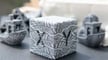
This test highlights the effects of staircasing on prints based on the slope’s angle. Staircasing is the appearance of tiny steps instead of smooth curves, an almost unavoidable result of producing a part in layers.
This design includes nine different angle arrangements (each of two angles that add to 90°) starting from 5° and 85°, letting you see which angle works best to minimize the stair-casing effect on prints with a slope.
What to change: Reorient the model so important slopes print at angles that minimize visible staircasing. If orientation is fixed, reduce layer height to make the steps less pronounced, at the cost of longer print time.
Once you find the right angle, you can properly orient models that contain a curve so that the curve is at the determined angle and the slope will look more uniform and natural. Alternatively, you can print a few of these calibration models at different layer heights and use the one that works best.
- Who designed it? Devstroyer
- Where to find it? Cults
The Best General Benchmarks and Torture Tests
3DBenchy
- Best for: A recognizable all-round visual benchmark
- Not suitable for: Isolating one calibration setting
- Changes settings during printing: No
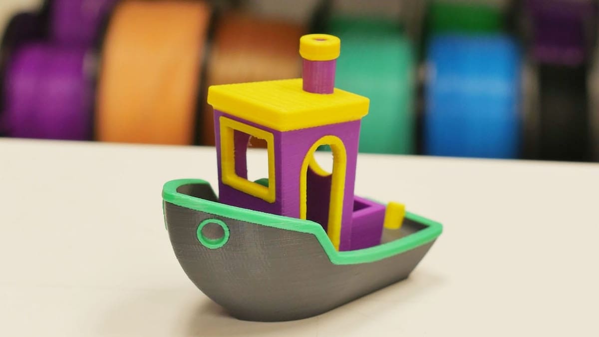
Few 3D printer test prints are as recognizable as 3DBenchy. The small boat combines curved surfaces, bridges, overhangs, holes, text, fine details, and abrupt direction changes in one support-free model.
Its greatest advantage is comparability. Because so many makers recognize a Benchy, its defects are easier to discuss and compare than those of an unfamiliar model.
Inspect:
- The first layer and lower hull for elephant foot
- The bow for cooling and surface consistency
- The cabin doorway and windows for bridging and overhang quality
- The roof and chimney for clean extrusion
- The gap between features for stringing
- The surfaces after corners for ringing
- The small text and rear details for resolution
A poor Benchy tells you where to investigate, but it rarely identifies one root cause by itself. For example, strings can result from temperature, retraction, moisture, or nozzle contamination. Sagging can involve cooling, temperature, bridge flow, or speed.
Use the visible symptom to select one of the focused tests above.
3DBenchy was designed by CreativeTools specifically for testing and benchmarking 3D printers. The official site provides links to several authorized download locations.
And while there’s been a bit of controversy at the beginning of 2025, the little boat that could has been relicensed under CC0.
- Who designed it? CreativeTools
- Where to find it? Thingiverse, Printables
Cali-Dragon
- Best for: A quick and attractive visual quality check
- Not suitable for: Precise single-variable calibration
- Changes settings during printing: No
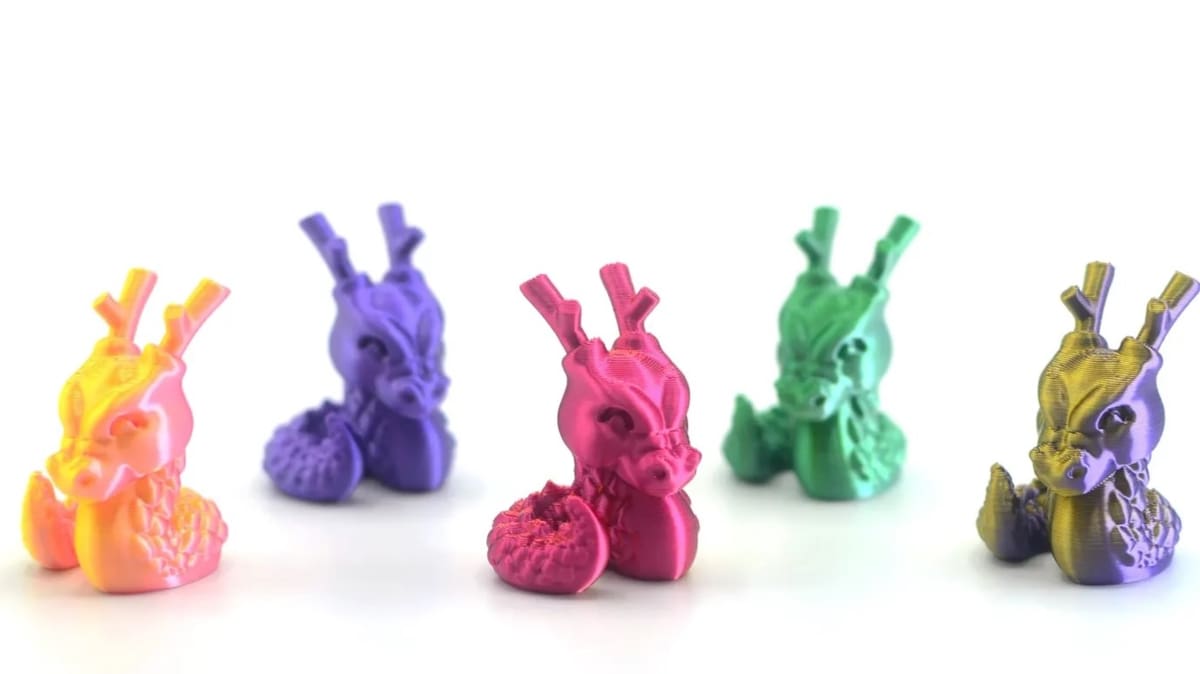
Cali-Dragon turns a calibration print into something worth keeping on a shelf.
The compact dragon includes curves, small horns, overhangs, recessed details, a tail, and varied surface geometry. Those features can reveal cooling problems, stringing, ringing, inconsistent extrusion, loss of detail, and weak small features.
Its organic shape is useful because it resembles the decorative miniatures and models many people actually print. It can expose defects that are less obvious on a simple cube while remaining faster and less demanding than a large figurine.
Check:
- The horn and ear tips for cooling and minimum-feature performance
- The underside of the chin and body for overhang quality
- The tail and gaps for stringing
- Curved surfaces for ringing or inconsistent extrusion
- Small recessed features for resolution
- The base for elephant foot and adhesion
Because the model combines several challenges, follow up with a focused test before changing a setting.
Cali-Dragon was created by McGybeer and is available as a free model on Printables.
The creator says that it can be printed with no infill at all, and other printing parameters like layer height and wall count will be defined as the way you wish to test the parameters of your printer. A suggestion is to start with a 0.2-mm layer height and three walls, then tweak according to your needs.
- Who designed it? McGybeer
- Where to find it? Cults, MyMiniFactory, Printables, Thingiverse
All-in-One
- Best for: Checking several visible capabilities in one compact print
- Not suitable for: Claiming that one result has calibrated temperature or belt tension
- Changes settings during printing: No
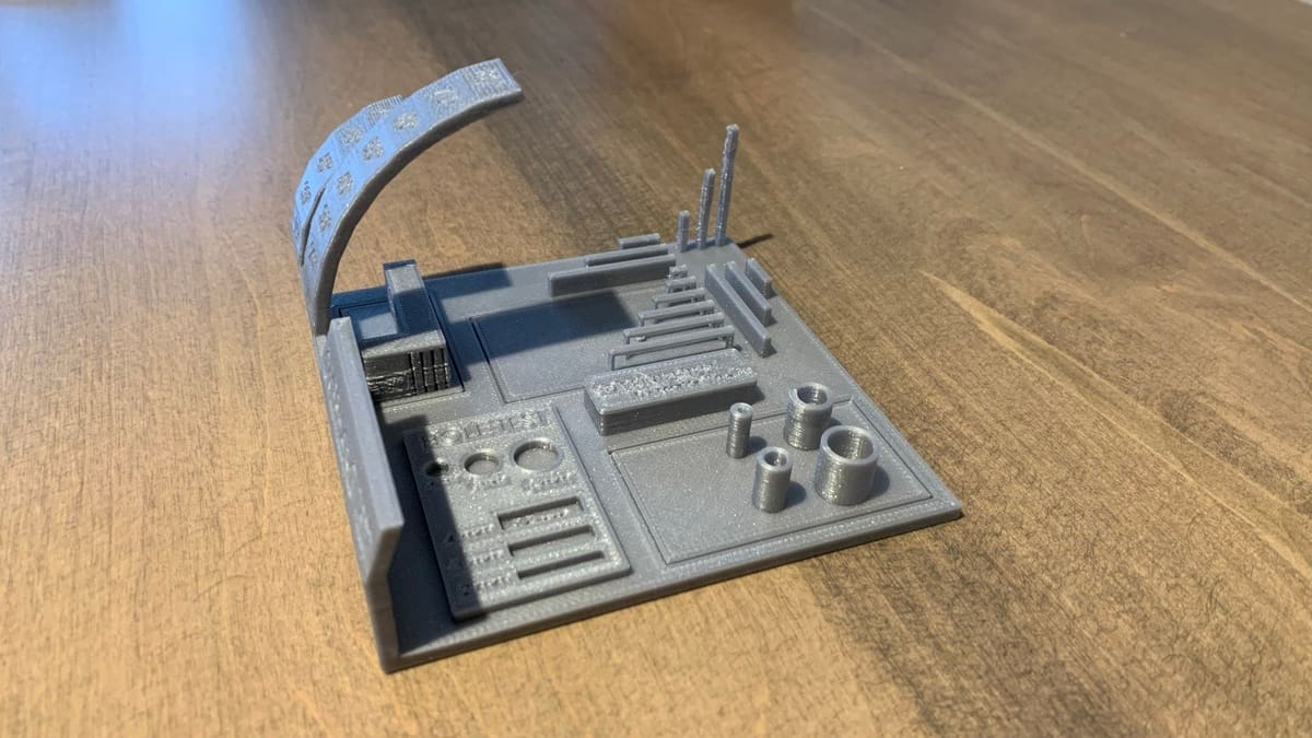
The All In One 3D Printer Test by majda107 combines several familiar challenges, including bridges, overhangs, stringing towers, holes, sharp points, and dimensional features.
That makes it a useful broad benchmark after you have established a working profile. It can also help you compare a printer before and after maintenance or compare two slicer profiles using the same material.
The model can reveal symptoms associated with:
- Bridging
- Overhangs
- Cooling
- Stringing
- Surface finish
- Hole quality
- Dimensional accuracy
- Ringing
- First-layer behavior
However, a static all-in-one model does not independently calibrate nozzle temperature, extrusion, or belt tension. Several different causes can produce the same visible defect.
For example, strings between the towers may involve moisture, temperature, retraction, nozzle contamination, or pressure control. A rough bridge may involve cooling, temperature, speed, or bridge flow. Use the model as a map that points toward a more focused test.
If you want to test your printer on multiple layers (pun intended), be sure to try this torture test!
- Who designed it? majda107
- Where to find it? Thingiverse
The Torture Toaster
- Best for: A challenging print-in-place mechanism
- Not suitable for: Beginners looking for the first setting to calibrate
- Changes settings during printing: No
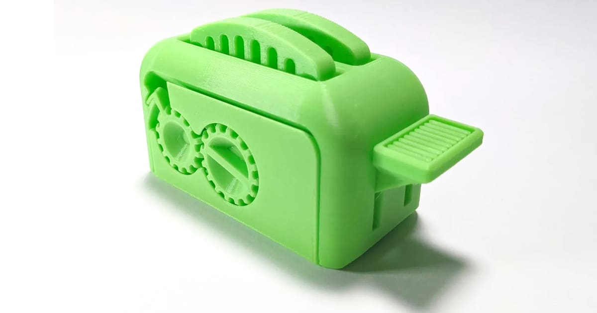
The Torture Toaster is an articulated, print-in-place toaster with hinged doors, moving parts, and pieces of toast operated by a lever. It is designed to challenge clearance, overhang handling, and bed adhesion. If the print succeeds, the parts should release and move without requiring assembly.
That makes the toaster a satisfying final exam after you have tuned the first layer, flow, pressure advance, cooling, and practical clearances.
If the mechanism is fused:
- Check whether elephant foot closed the lower gaps.
- Compare the required clearances with a focused tolerance test.
- Check flow ratio and pressure advance.
- Look for strings or blobs inside the moving joints.
- Confirm that the model was printed in the intended orientation.
- Make sure no brim or support was added where it could join moving parts.
Do not force the mechanism immediately after printing. Let the model cool and follow the creator’s release instructions.
A failed Torture Toaster does not mean the printer is defective. Print-in-place mechanisms intentionally push clearances and unsupported features beyond what many ordinary parts require.
This print-in-place toaster is designed to verify tolerances, overhangs, and bed adhesion. If all goes well, you should be able to push the lever to pop the toast up, just like on a real toaster. However, if your printer isn’t up to the task, your toast won’t be able to move!
The creator recommends printing with 20% infill and a 0.2-mm layer height as a starting point. No brim or supports are required.
- Who designed it? Clockspring
- Where to find it? Printables, Thingiverse
Cali Cat
- Best for: A fast, friendly visual check
- Not suitable for: High-precision dimensional calibration
- Changes settings during printing: No
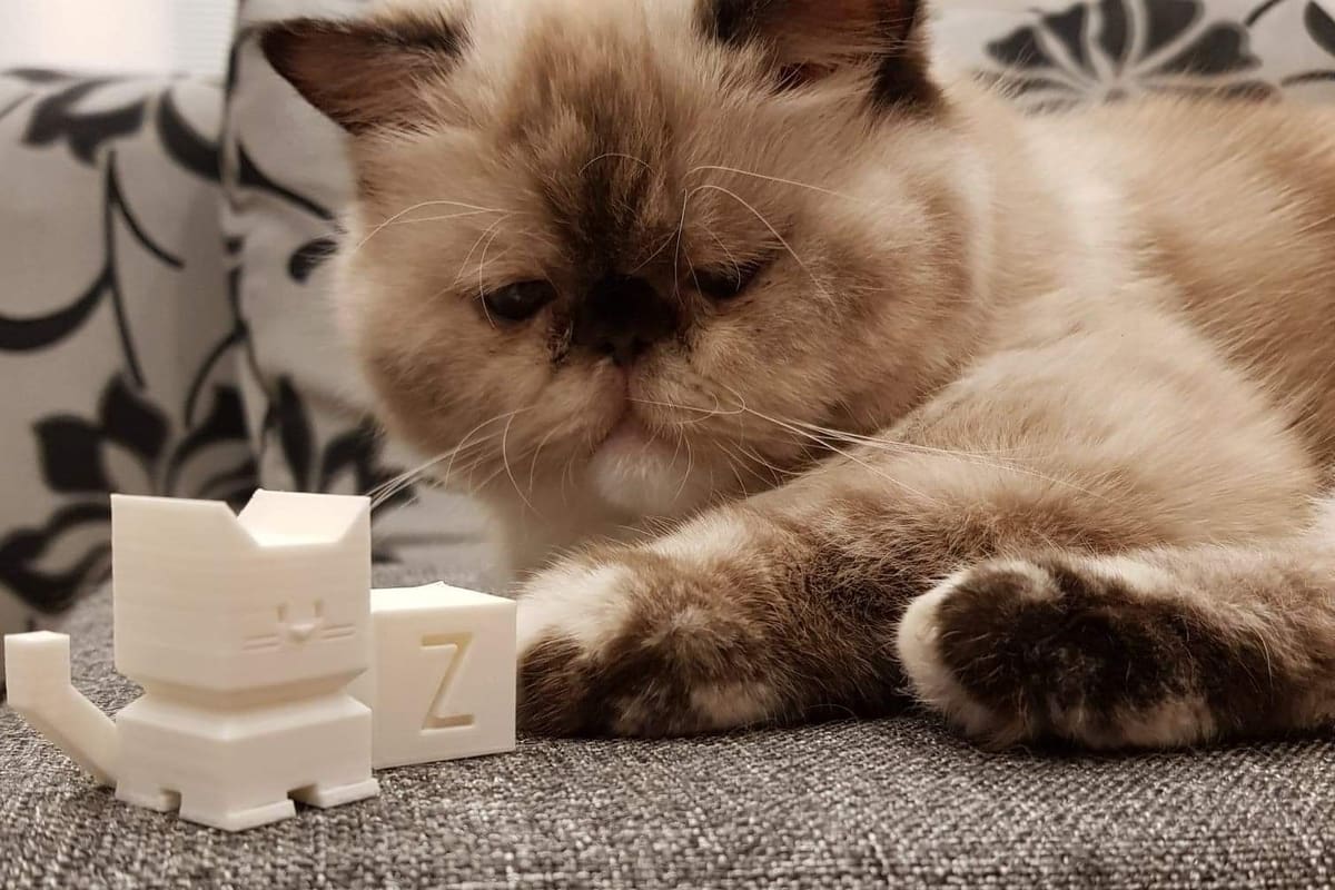
Cali Cat is a compact calibration model shaped like a cat. It provides more visual interest than a cube while retaining several easy-to-inspect geometric features.
The model can reveal:
- First-layer problems around the feet
- Ringing after sharp corners
- Overhang quality beneath the head and tail
- Stringing in gaps
- Surface inconsistency on the body
- Loss of detail around the face and ears
- Dimensional or fit problems when using the creator’s stacking feature
Cali Cat works well as a quick profile comparison or first print with an unfamiliar material. Its flat and curved surfaces make defects easy to see without the longer print time of a large torture model.
As with Cali-Dragon and Benchy, use it to spot symptoms rather than to select exact calibration values. If the ears are rough, move to a cooling or overhang test. If the body shows repeated waves, use a ringing test. If the tail strings, investigate temperature, material condition, and retraction.
Designed for initial calibration, this cat will help you achieve purr-fect prints in no time at all.
Pro Tip: If you print one cat twice as big as another, the small cat will fit squarely on top of the big one.
- Who designed it? Dezign
- Where to find it? Thingiverse

3D Boaty
- Best for: A decorative general benchmark and alternative to Benchy
- Not suitable for: Focused calibration
- Changes settings during printing: No
If a boat can be named after a bench, a bench can be named after a boat.
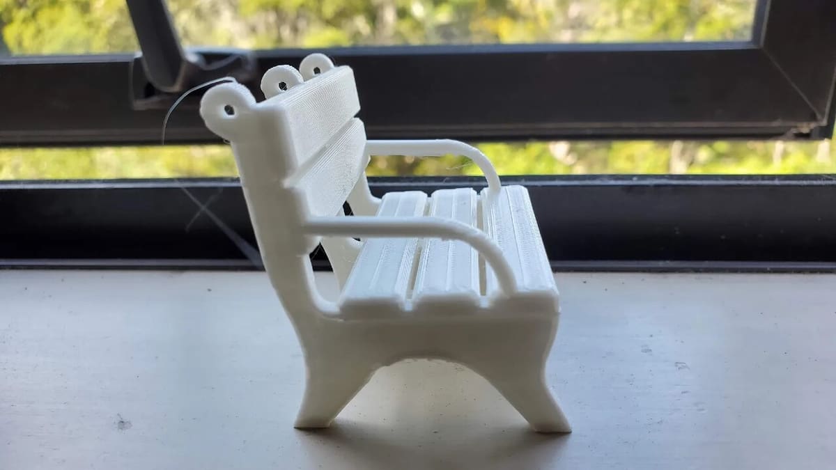
3D Boaty is a miniature bench that provides a playful alternative to 3DBenchy. Its slats, legs, curved edges, gaps, and unsupported features can reveal adhesion, bridging, overhang, hole, cooling, and surface-quality problems.
The model is most useful as a broad check of a profile that is already close to working. It also leaves you with a decorative object rather than an abstract calibration shape.
Inspect the undersides of the seat and back, the spaces between slats, the contact points at the build plate, and any repeated artifacts after corners. Follow up with a dedicated bridge, retraction, first-layer, or ringing test where necessary.
When printing this, you can check a score sheet and compare your model to see how well your printer is working. For each leg of the stool that loses adhesion, for example, 1 point is deducted – and 6 points are deducted if you use a brim. Users like coarel point out that it can be a much rougher print than the famed Benchy.
- Who designed it? Depep1
- Where to find it? Printables
Frequently Asked Questions
Is Benchy a Calibration Print?
Benchy is best treated as a benchmark and diagnostic print. It contains many challenging features and can show that something is wrong, but it usually cannot isolate one parameter. Use a focused calibration test to investigate the symptom visible on the Benchy.
Do Auto-Leveling 3D Printers Still Need a First-Layer Test?
Yes, although the amount of manual adjustment varies.
Automatic probing can compensate for variation across the build surface, and some printers automatically determine the nozzle’s first-layer position. It does not guarantee that the plate is clean, the nozzle is undamaged, the material is extruding correctly, or the selected profile is appropriate.
Some newer printers use a load cell to calibrate the first layer automatically before a print, for example, while older models use a manually adjusted first-layer value.
Should I Calibrate Every New Filament?
At minimum, verify a new filament using a suitable manufacturer or community profile and a small test print.
More detailed temperature, flow, pressure-advance, retraction, and maximum-flow calibration is worthwhile when:
- The material or formulation is unfamiliar.
- The default profile produces visible problems.
- You need strong, dimensionally consistent, or high-speed parts.
- The filament color behaves differently from one already tested.
- You have changed the nozzle, hot end, extruder, or printing conditions.
Save successful values in a named filament profile rather than changing the printer’s global settings.
How Often Should I Recalibrate a 3D Printer?
Do not recalibrate everything on a fixed schedule merely for the sake of it.
Run the relevant check when:
- Print quality changes
- A new material behaves differently
- The nozzle, hot end, extruder, bed, or toolhead is changed
- Belts or motion components are adjusted
- Firmware or a major slicer profile is changed
- The printer is moved or rebuilt
- Higher print speeds are introduced
Use a quick benchmark to confirm that the printer still behaves as expected, then run only the focused test related to the visible problem.
Why Does My Test Print Still Look Bad After Calibration?
The chosen setting may not be the root cause. Check the basics again: filament condition, nozzle cleanliness, extruder grip, spool resistance, hot-end assembly, cooling fan, belts, pulleys, wheels or rails, frame fasteners, build-surface cleanliness, and profile compatibility.
Also confirm that the test actually varied the parameter it was supposed to vary. A temperature tower accidentally printed at one temperature can look informative while providing no valid comparison.
You May Also Like:

License: The text of "18 Free 3D Print Test Models, Plus How to Fix Everything from Stringy Prints to Bad First Layers" by All3DP is licensed under a Creative Commons Attribution 4.0 International License.