J3DTech Guide to Resin 3D Printing
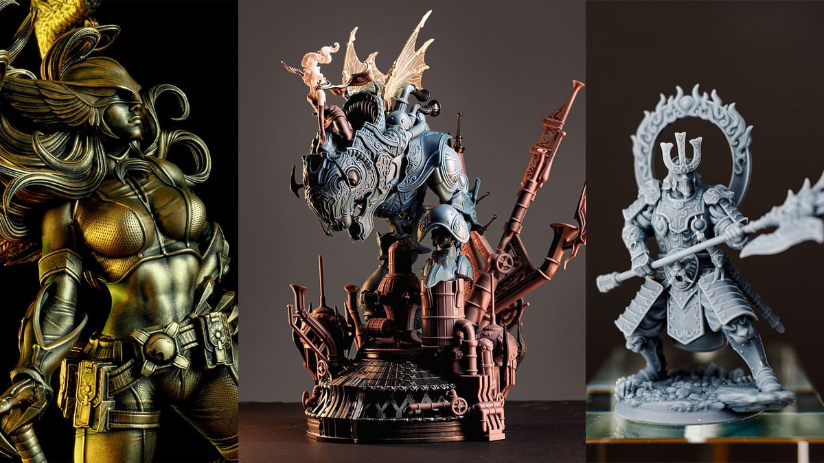
The J3DTech Guide to Resin 3D Printing is a beginner's primer and a veteran's reference for all things resin 3D printing.
Notice of conflict: Derek "J3DTech" Jackson is an employee of Lychee.
Years ago, this guide began as a simple email to a colleague, after seeing his 3D printer in rough shape. I wanted to share the process I had developed to help him care for his printer and avoid future mishaps. What started as a small gesture has grown into something far beyond what I ever imagined. To everyone who has read and supported this guide over the years, thank you. I hope it has been a helpful companion on your journey, just as it has been on mine.
If you’re new to resin printing I strongly recommend you first read the Terminology guide. J3D Tech’s Terminology Guide to Resin Printing
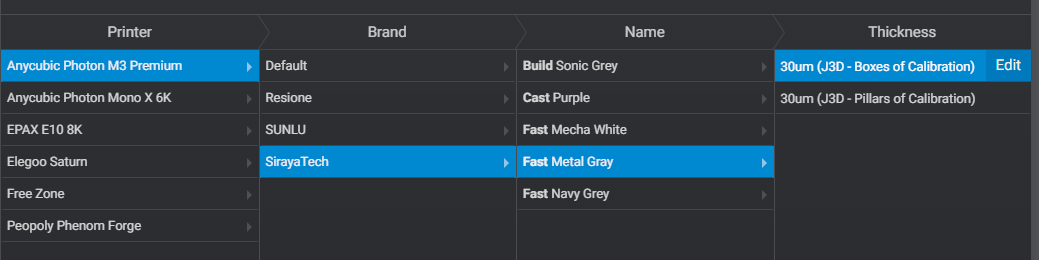
I use Siraya Tech Navy Gray, with 15% Tenacious Obsidian Black for all my examples and prints. This guide is based on Lychee Plus, you can Download the Free Version here.
Prepping Your 3D Printer
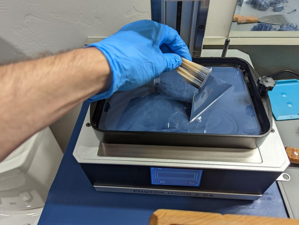
To begin your 3D printing journey you must first squeegee the release film using a soft silicone spatula. If you don’t have a spatula, buy one.
Don't use the hard plastic scraper that comes with your printer, it will scratch the FEP. If you damaged your FEP I recommend the Siraya-Tech nFEP
Do this before every print, always! Failure to do this will lead to permanent damage to your 3D printer.
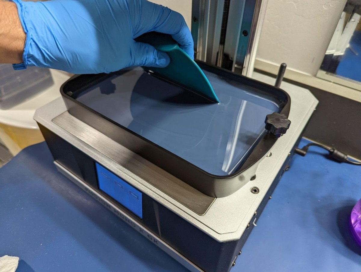
By doing this, you’ll accomplish three important things:
- Check for hard bits – These could be remnants of failed prints. Even after a successful print, tiny hard pieces may still be stuck to the release film.
- Inspect for damage – Check the release film for any signs of wear or damage.
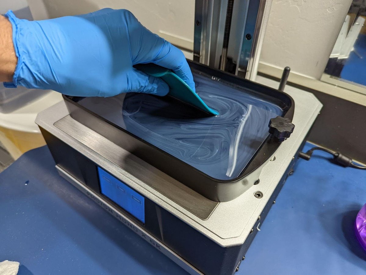
- Mix the resin – Before your next print, always mix the resin. In many resins, you can see the pigmentation separate, though in some, it’s not visible. Either way, it’s happening! Mixing ensures that any pigment that has settled on the release film, which could negatively impact the print’s adhesion to the build plate, is fully reincorporated into the resin.
If you feel a bump when using the Squeegee, run a VAT clean. Watch the video below for instruction.
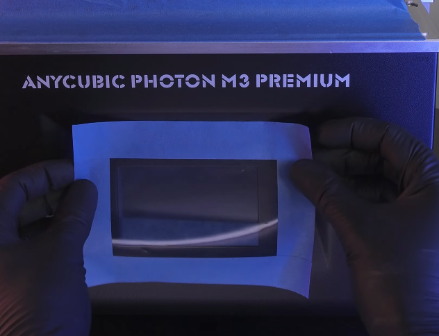
If you still feel a bump even after running a VAT clean, you most likely have a damaged FEP. Use a mirror or empty the VAT to check the condition of the release film. Replace if necessary, see this next video for inspiration or refer to your printer’s user manual.
You can also protect your 3D printer by making a little tape go a long way:
If you prefer video, check this out! Remember to subscribe!
13 Simple Hacks to Make Your Printer Last | Lychee Tips
Leveling the Build Plate
Leveling the build plate is the most critical step you can take. It does not matter if everything is perfect. If your bed is not level, it will not print.
Many new 3D printers have “Auto Leveling”, but most will still need to be manually leveled.
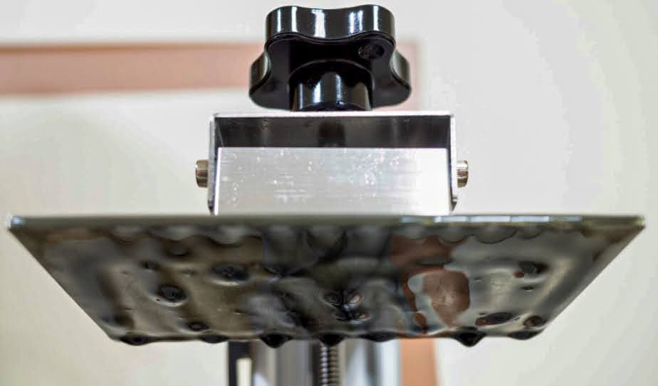
Vat Method
This is my preferred method. Why?
Apply medium pressure on the plate. Lightly tighten in an X pattern. This will change depending on your printer but the theory is the same. Don’t make them tight on the first pass.
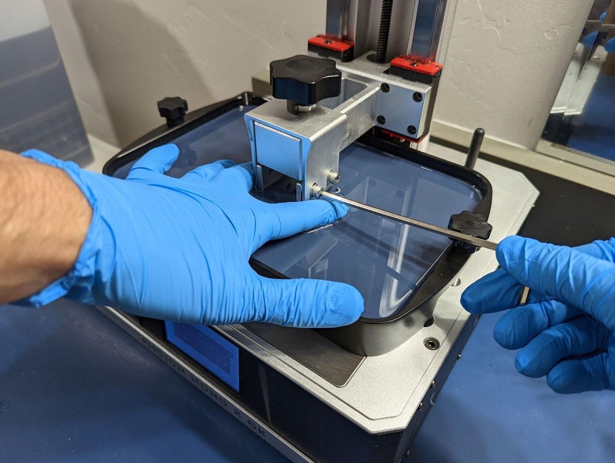
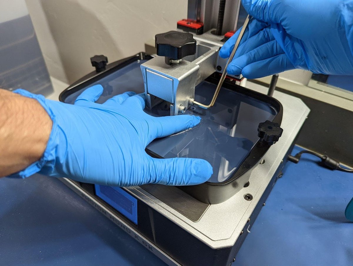
After about 4 passes. Reposition the wrench for the final tight, but do not strip your bolts tight.
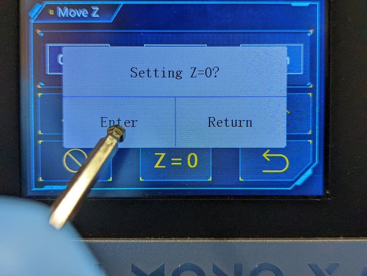
Reset Zero or Z=0
Not all printers have this option. If yours does, it needs to be done right after you level, while the build plate is down against the LCD.
Some printers with “Auto Leveling” have removed this function. Making us all suffer as a crucial feature was killed.
Paper Method
If you’re still not sure how to do this after reading this seciton, see your printer’s manual for specific instructions. For printers with a ball joint like the Saturn series, my VAT Spacer is needed for VAT leveling.
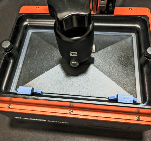
These function by preventing the build plate from rotating making leveling even easier than the paper method.
If you’re more comfortable with paper leveling, or your printer is 13″ and larger:
- Use a sacrificial FEP sheet as your leveling method.
- This will better simulate your VAT.
- Won’t get paper fibers all over your LCD.
- Will protect your LCD from resin that may get through the paper from the build-plate.
- If you don’t have a spare FEP sheet, I recommend using 2 pieces of normal paper, or 1 if it’s very thick.
To confirm that your printer is level, you'll want to use the Build Plate Calibration parts. For now keep reading to learn more about the resin and printer settings you will need for calibration.

If you’re having issues you can't solve, read the Troubleshooting Print Failures section below.
The best resin settings for your printer | Lychee Slicer Tutorial (Beginner-Friendly)
The following chapters are covered in this video.
Normal Layer Print Settings
Burn-in-Layer Layers Print Settings
Two Stage Motion Control, (TSMC)
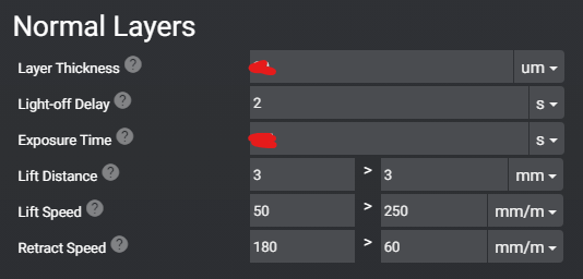
Normal Layer Print Settings
In this chapter, I will cover all the settings found under Normal Layers.
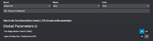
- Global Parameters (very important!)
- If your printer is using a Chitu System motherboard you will see (Global Parameters) If you don’t, move on to #2.
- If available, set it as shown below.
- Having both on will trigger a Chitubox related bug that will cause neither to work correctly.
| Anycubic Printer
|
Chitubox Printer
|
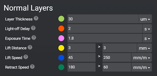
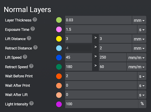
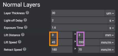
The > symbol means “and then”.
In this example. The printer will lift 3 mm and then lift another 3 mm, a total of 6 mm. This is explained more in the TSMC chapter below.
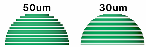
Layer Thickness: This is how thick each print layer will be. The lower the number the thinner the layer. Gaining more detail at the cost of longer print times.
- Objects with lots of curves or steep edges can benefit from more layers as it will reduce stepping. This is represented in the image below. The sharper the angle (the top) the more apparent stepping becomes.
- Once you have decided what layer thickness you want to calibrate your printer at, we can move to the next setting (Default and most common is 50 micron).
- I print at 30um for show pieces, however larger objects like terrain and props for a D&D set, I recommend 50um or higher. However you will need to develop a new profile.
Light off Delay / Wait Before Print: A short pause after the printer has fully retracted and before the UV light turns on to cure the resin.
- Gives time for the printer to come to full rest. Lesser known fact: When the motor stops, the printer is still moving. Until the printer’s flex is fully at rest.
- Gives time for bubbles to escape
- I’ve seen little benefit above 3.0/s. Unless you have a very large printer or use a very thick resin. There is also a great article that goes into detail here.
Exposure time◼︎: This is the setting we are printing the calibration tool to adjust. Use your resin’s recommended UV settings.
- How long will each layer be exposed to the UV light?
- Your slicer will have two settings for this. Burn-in / Bottom layers and Normal Layers.
Lift Distance◼︎:
- The distance your printer will lift after exposing each layer.
- If you don’t lift enough you risk the print not separating from the release film. This will cause failed prints or layer lines.
- Lifting too much will increase the print time and can have a negative impact on your print quality.
- Remember, what goes up must come down. If you lift – lets say 5 mm + another 5 mm a total of 10mm. You have to come back down 10mm. A total of 20 mm movement per layer. This will increase the print time for no gain. It may even damage your print due to pushing the print though more resin.
- I have found that for any 10” printer 3 mm + 3 mm a total of 6mm up and down is more than enough. You could even get away with a little less but I suggest staying in the safe zone of 6 mm.
Lift Speed◼︎: how fast the build plate will rip the model off of the FEP after each layer. See the examples below for speeds.
- The faster the lift speed the higher chance of layer separation, support failure and build plate separation.
- The faster the lift speed, the faster your print will finish.
- Slower lift speeds greatly increase the success rate and the life of your printer.
- The settings in these examples are what I use on all of my printers and most resins.
Retract Speed◼︎: how fast the build plate will lower. See the examples below for speeds.
- With larger printers, it’s very important to slow down the retract speed. Lowering the plate with a large print will put a lot of pressure on the FEP and, more importantly, the screen. Some plates (like the Mega 8K one) have holes. The purpose is to limit the pressure to avoiding killing your expensive 8K screen.
Retract Distance◼︎: only available on Chitu Systems Motherboard and when using TSMC, explained below.
- Allows you to set two speeds on retract. The goal is to go faster when the build plate is further away from the LCD. Slowing down as the print gets close to the LCD to protect the print and printer and get an overall more accurate print.
- Lowers the PSI created by compressing the Resin to the desired layer height while also preserving some print speed.
Light Intensity◼︎: Found on Chitu Systems Motherboards this lets you set the UV power.
- Lowering the UV power to 60%-70% can help to get higher accuracy when dealing with speed, white or clear resins.
- If you change this setting, you will need to recalibrate.
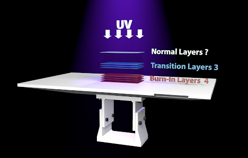
Burn-in-Layer Layers Print Settings
These are the first layers printed and need to be exposed to UV light for much longer than normal layers. This is so the resin will adhere to the build plate during the remainder of the print.
| Anycubic Motherboards
|
Chitubox Motherboard Printers
|
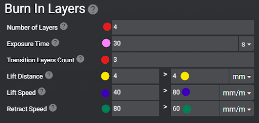
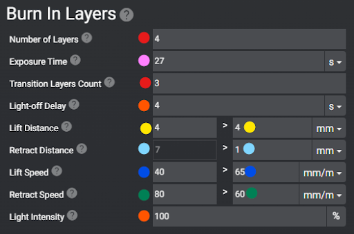
These settings only affect the first layers printed in this example, only the first 4 layers.
Exposure Time◼︎: use your resin manufacturer recommended settings. This can always be calibrated later.
- On Burn In Layers, this will directly impact how well the print sticks to the build plate.
- Every resin is different, calibrate this for each resin, printer and layer height.
- Go up or down by 4/s until prints come off easily but still hold firm.
- Develop a different burn in Exposure Time for each size of print.
- Small = calibration print or small parts
- Medium = Minis or parts of a larger print
- Large = Terrain or a very large statue
- Using Navy Gray a “Fast Resin” I’ve found my numbers are around:
- 15-24/s for small
- 27-34/s for medium
- 35-40/s for large
Transition Layers◼︎: will transition away from the burn in layer settings to the normal layer settings.
Light-off Delay◼︎: When using an Anycubic printer, you will only have light off delay listed under the normal layers. However, this setting applies to all layers. If your slice ends in .ctb, only the settings under the normal layers will be used. If your printer can slice using .prz (Phrozen) or .goo(Elegoo) the wait times under Burn in layers and Normal Layers will be used.
Lift Distance◼︎: set this to 25% higher for Burn in Layers over Normal Layers. This is because these layers will be the most difficult for your printer to remove from the FEP. The result of larger cross sections and longer burn in time.
Lift Speed◼︎: should be slow for burn in layers. No greater than 40mm/m. This is because as stated before, these layers are very difficult to remove from the FEP.
Retract Speed◼︎: needs to be set very slow for Burn in Layers. This is because the build plate is trying to push the resin against the LCD under incredible pressure. So much pressure that the frame and arm of your printer will flex and bend.
- If your model is hard to remove from the build plate remove 4s from Exposure Time till they are firm but easy to remove.
- If your models keep falling off the build plate and your exposure is already above the resin manufacturer recommended. Try the following Instead of burning out your LCD light by adding more Exposure time.
- Increasing surface area on the build plate by using a larger raft.
- Slowing down your retract speed to 40mm/m or lower.
- If your printer does not have a separate retract speed for burn in layers. Try lowering it down to about 60mm/m or lower!
Two Stage Motion Control (TSMC)
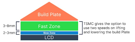
Primary Objective: Speed up your print time while keeping the same accuracy and success rate.
Objective 2: Have the model Pop from the FEP 98% of the time during the slower Lift Speed.
Objective 3: Have enough total lift height to never have a failed FEP release.
Objective 4: Reduce print time.
Don’t lift the print so high that the printed surface of the model is lifted out of the resin. Exposure to air can cause failure or layer lines.
Now that you know what Lift/Retract distance and lift speed are, let’s apply that knowledge. If you prefer a video explaining TSMC over reading, watch below.
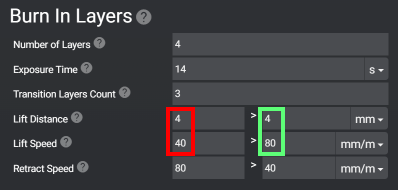
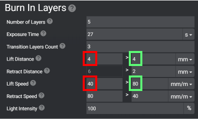
Burn-in / Bottom layers
In this example, I’m lifting the plate a total of 8mm. 40 mm/m for the first 4 mm plus 80 mm/m for the final 4 mm. That’s right, as I stated before these numbers are added together.
For Retract speed you will notice that the lower number is in the right field.
| Example of an Anycubic Printer
|
Example of a Chitubox printer
|
Normal Layers
In this example, I’m lifting the plate a total of 6 mm. 45 mm/m for the first 3 mm and 200 mm/m for the final 3 mm. For Retract speed you will notice that the lower number is in the right field.
| Example of an Anycubic printer
|
Example of a Chitubox printer
|
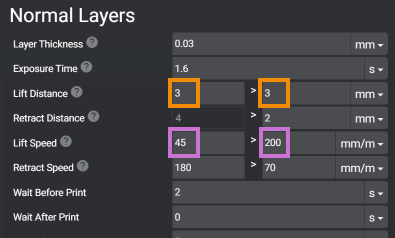
The two differences between Chitubox printers and Anycubic are:
- The ability to also adjust the retract distance. Don’t get confused by this, simply put a 2 in the left box. (The right box can’t be edited as it’s based on the lift height.)
- Wait before print instead of Light-off Delay, they do the same thing.
Resin Calibration Prints
Build Plate Calibration
The Build Plate Calibration tool is a resin 3D print designed to help users ensure their build plate is properly leveled, calibrate burn-in time, and set the Z-offset for accurate prints. It identifies leveling issues by comparing the thickness of five test plates placed across the build area. Proper Z-offset calibration prevents layer crushing, which can shorten prints, damage the FEP, and cause print failures. By measuring and adjusting based on the tool’s results, users can achieve a level build plate and optimal first-layer adhesion, improving overall print quality and consistency.
Download the test model here and watch the video below to understand how important this is.
This model is designed to do three things in a 15 min or less print:
- Verify that your build plate is level
- Calibrate your Burn-in time
- Check and set Z-Offset
Why do we care about the Z-offset?
Most new 3D printers with “Auto leveling” can’t do this. RIP being able to properly calibrate your printer.
Layer Crushing is when your print is shorter than it should be. This is often because the printer is starting at a height below the set layer thickness.
Layer crushing will mostly work itself out during the entire print. But overall your print will be a tiny bit short. The worst side effects of layer crushing are:
- More damage to the FEP. This is because each layer will be pushed into the FEP over thousands of layers.
- Pushing into the FEP can displace all the resin. This will cause thin or partial layers. This may result in split-rafts. Supports and smaller details to simply just stop printing.
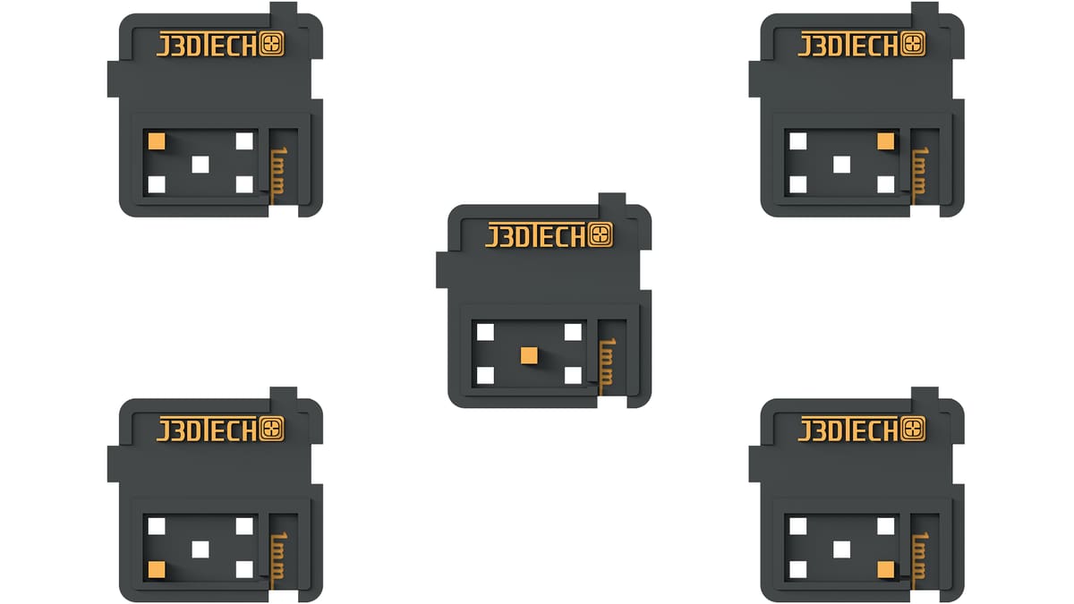
How to Use the Test Print
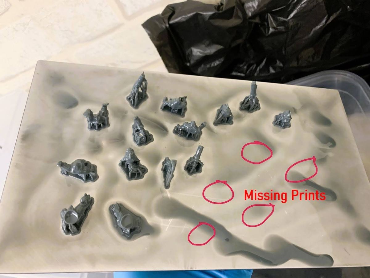
Arrange the 5 flat plates on the build plate in a dice pattern. Each part has a symbol on it that helps identify where it was on the build plate. Notice the orange boxes in the picture above; its location correlates to the part position.
I suggest curing them for about 30-60 seconds. This won’t alter their accuracy but will make them safer to handle.
Verify that your build plate is level
Are any missing?
- If you’re only missing the center?
- This could mean that your Build Plate is not flat.
- Use a flat metal ruler and flashlight to confirm. Contact the Printer Support of its so bad you can’t get anything to stick to the center.
- If you’re missing 1 or two on a single side?
- This means that you’re not even close to level.
- What to do? Level again and do better!
- Try printing my Leveling Jig to make your life easier.
Do you have digital calipers?
- Yes! Measure the raft on the thinnest part. For now, it does not matter how thick they measure, all that matters is that the 4 outer rafts measure within 0.2mm.
- If the 4 outer parts are 20% of the same thickness, you’re level!!!
- If not, level again and do better!
- The center of most printers will be higher or lower than the sides, this is normal.
- No! You can lock the four outer rafts using the notches, then use your finger nail to feel for a large height difference. It may sound funny but doing this will get you “close enough”.
- If all five are about the same thickness, you’re level! If not, level again and do better.
- If you’re looking for digital calipers, know that you don’t need expensive ones – they are not more accurate.
Calibrate your burn-in time
This step repeats some instructions under "Burn-in-Layer Layers Print Settings" in the Prepping Your 3D Printer section of this guide.
Check and set the Z-Offset
For this you will need Digital Calipers – I’ve tested a few methods to not need them, but precision is required.
Measure the 5 Plates and write it on the front, remember they are supposed to measure 1mm on the thinnest section.
If they measure UNDER 1mm
- Find the average of the 5 plates
- Refer to your user manual and use the front LCD on your printer on how to set your z-offset.
- Subtract the thickness of the raft from 1mm. This is your Z-offset.
- Example, if your raft measured at 0.4mm. The z-offset would be 1 – 0.4mm = 0.6mm
- If it takes more than one time to get it right, you must enter in the total value. For example, if after adding 0.2mm it was still 0.1mm short, you would need to enter in 0.3mm as the printer will only read the current value entered.
- Print and test again. They should be good!
If they measure OVER 1mm
- If they are over by 0.1 – 0.2mm you’re honestly fine, move on with your life.)
- If they measure greater than 0.4mm
- Refer to your user manual and use the front LCD on your printer
- ONLY remove the difference + 0.1mm or you risk going too low and causing layer compression.
Example. If they measure 1.4mm then only subtract 0.3mm from your Z-Offset. - If it takes more than one time to get it right, you must enter in the total value. For example, if after removing 0.2mm it was still 0.1mm tall, you would need to enter in 0.3mm as the printer will only read the current value entered.
- Print and test again. They should be good!
Let's Talk About Normal Layer Calibration
Calibration is not just about setting the UV exposure time, there are other very effective tools. Let’s talk about how to use them.
- Light off Delay (LOD) can be just as effective as lowering UV exposure time to get better accuracy.
- 2-3/s for normal resin
- 3-4/s for resin that’s thick like honey
- 10+/s for resin that’s like warm rubber.
- Keeping your resin between 24 ºC and 30 ºC can do wonders for accuracy.
- Anything between the LCD and the resin will hurt accuracy. Keep a clean printer, check for dirty or damaged:
- LCD
- Release Film
- Screen Protector
- ACF Film
- Slow down, Turbo!
- Keep your first stage of lift speeds under 100 mm/m, maybe even under 50 mm/m
- Keep your retract speeds under 200 mm/m
- Don’t lift more than needed, it’s a HUGE waste of time!
- Burn in layers use 4 mm + 4 mm for a total of 8 mm
- For huge printers use 5 mm + 5 mm for a total of 10 mm
- When not using TSMC just use 8 mm
- Normal layers use 3 mm + 3 mm for a total of 6 mm
- For huge printers use 3 mm + 4 mm for a total of 7 mm
- When not using TSMC just use 5 mm
- Burn in layers use 4 mm + 4 mm for a total of 8 mm
- If you’re failing any of the tests listed below, consider all of these factors.
- The good news:
- Once calibrated, you can almost always use that setting forever.
- If the temps change more than 4c or you alter the layer height you will need ONLY calibrate again for the UV exposure time. All other settings remain the same.
- If you want to take a really deep dive into Calibration, see this article.
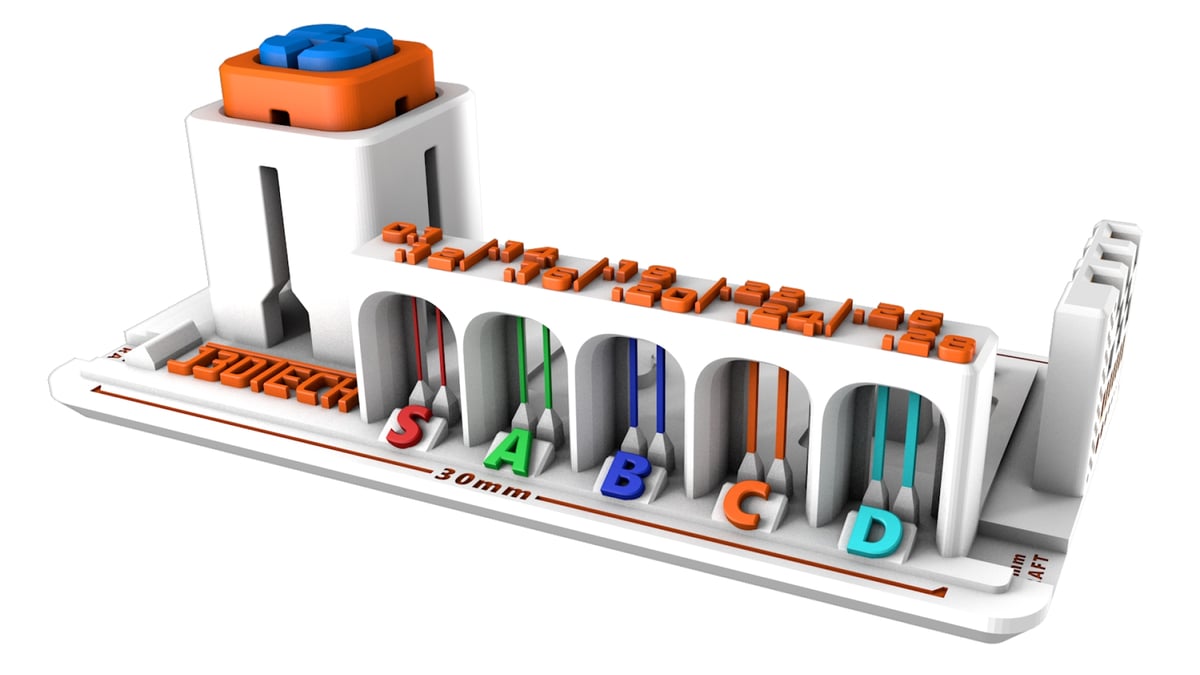
Boxes of Calibration
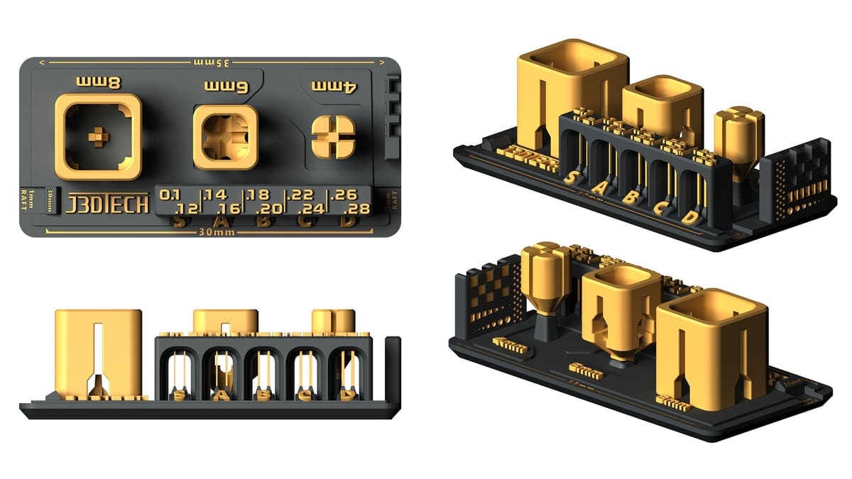
Download the Boxes of Calibration test print here. If you’re looking for a Multi Cure Calibration test (RERF), find one here.
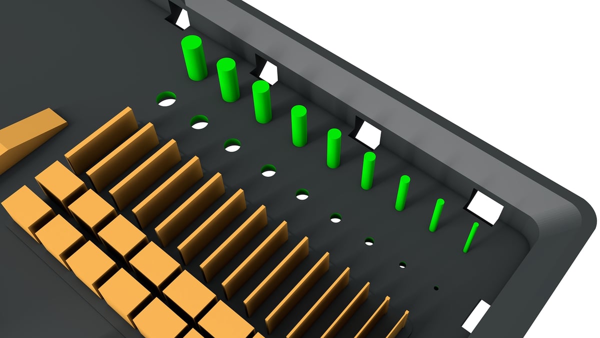
“Boxes of Calibration” is a 3D-printed test model designed to help you fine-tune your resin 3D printers for optimal performance.
The model consists of nested boxes and a series of pillars, each serving a specific calibration purpose. The nested boxes assess dimensional accuracy; when printed correctly, the smaller boxes should fit snugly into the larger ones without excessive force. The pillars, varying in thickness, test the resin’s tensile strength and the printer’s ability to reproduce fine details.
By adjusting printer settings based on the fit of the boxes and the completeness of the pillars, you can achieve precise and reliable prints!
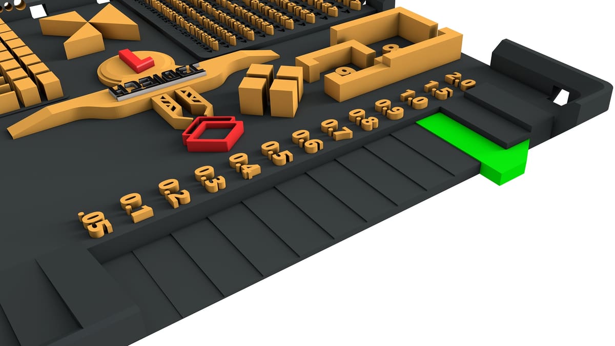
Boxes of Calibration Cheat Sheet
Objective: Get as many pillars as you can get, while the boxes fit.
- The Objective is not to get all the pillars to print or just get the boxes to fit.
- Not all resins are designed to do the same thing, so not all resins can get 10/10 pillars.
The more you increase the UV exposure time, the more pillars you can theoretically print. This is because UV exposure time does two things:
- Increases the hardness of the resin.
- The longer resin is exposed to UV light, the harder it will become.
- Blooming.
- Blooming increases the physical SIZE of the object, quietly swelling the object beyond the desired dimensions.
This becomes a game of tug-of-war between hardness and accuracy. This is what makes Boxes of Calibration a very unique calibration method. Because there is a control (The accuracy of the boxes), you don’t get to be naughty by increasing the UV exposure time to force all the pillars to print. Instead, you must consider other things that can increase accuracy.
Here is a list of things that affect the print quality in order of impact.
Resin settings:
- Light off delay (wait before print)
- Temps
- Retract speed
- Lift speed
- Lift height
The printer:
- The pixel size of the LCD, also known as XYum.
- Extra screen protector will greatly negatively impact quality. (The big ones that cover the entire printer offer the best protection, at the largest impact of quality.)
- nFEP vs ACF (nFEP is more accurate)
- Condition/ cleanliness of the release film and or LCD. (Depends on how bad the condition is.)
- Anything that could be causing the printer to be unstable or add excessive vibration. (Depends on how much vibration.)
Once calibrated, you can almost always use that setting forever. If the temps change more than 4 ºC or you alter the layer height, you will need only calibrate again for the UV exposure time. All other settings remain the same.
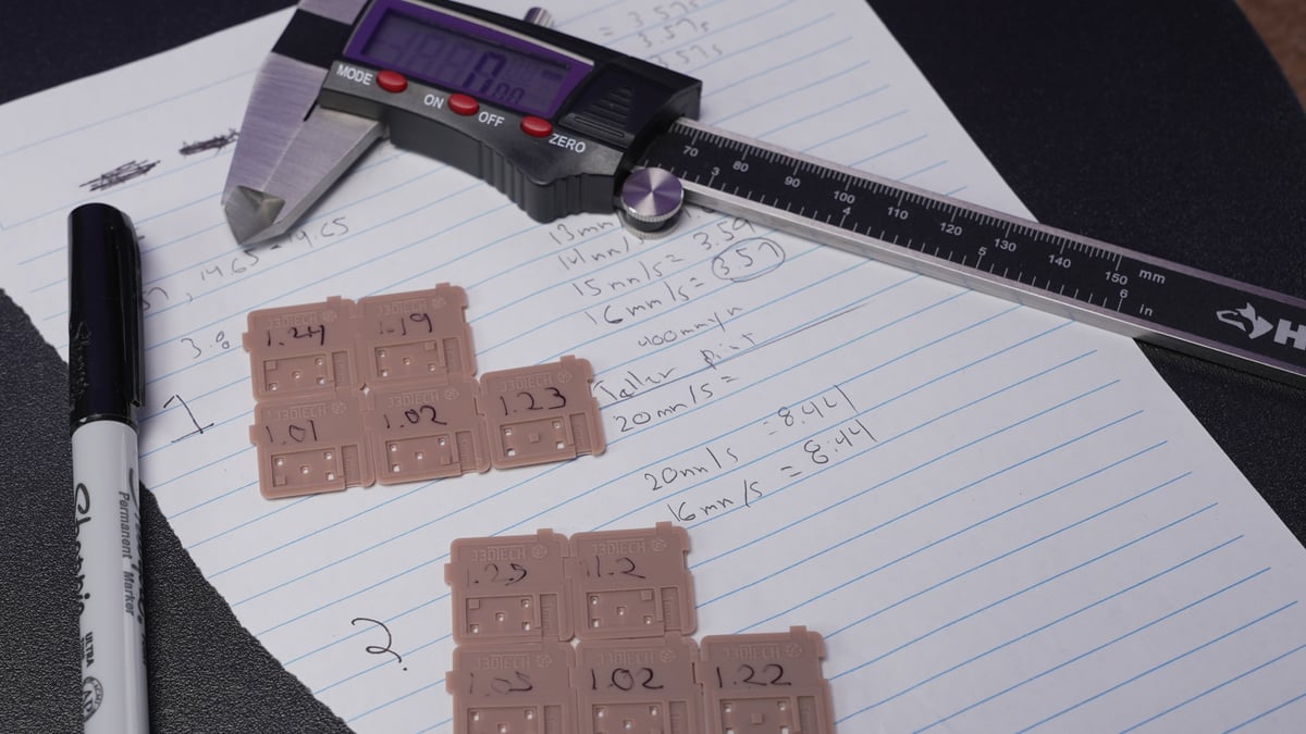
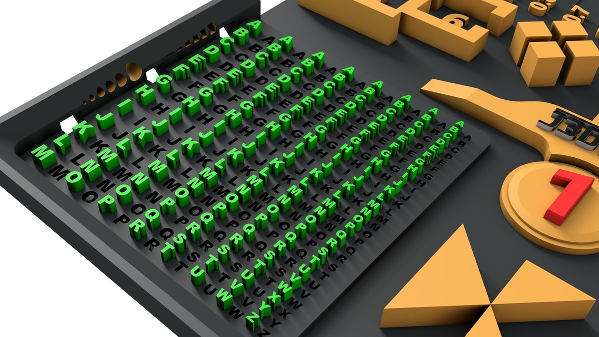
Reading Boxes of Calibration
First, cure them for 2-3 min to make them safe to handle. This will also make your measurements match a normal print.
The Boxes
If you don’t have digital calipers that’s ok. All you need to do is snap off the 4 mm and 6 mm Boxes. Once they fit inside of each other where you can still pull them apart you’re good to go.
If you’re looking for digital calipers, know that you don’t need expensive ones – they are not more accurate.
Boxes not fitting is mostly an issue of blooming, blooming is caused by a few major factors.
- Over exposure
- Curing resin in motion
- Dirty/damaged LCD, FEP or screen protector. The printer is in poor working condition.
- Layer elongation or layer crushing.
How to address each issue
- The boxes are too tight, reduce the UV exposure time on your normal layers.
- The boxes are loose, add UV exposure time on your normal layers.
- I recommend starting with 1s. As you get closer move to 0.1s changes.
- To resolve, start with 2s of light off delay. This will allow your printer, and resin to come to rest before the UV light turns on. Light off delay is also known as: Wait before print OR Wait after retract.
- Make sure your LCD, Screen protector, FEP are clean and free from major issues. Make sure your printer is well maintained. ACF film won’t be as accurate as nFEP and will damage the smaller pillars making them harder to print.
- Follow the Build Plate Calibration section in this guide.
To prevent damage to your FEP, rotate them 90º and move them by a few milimetres each print. This is true for any file you print more than one time.
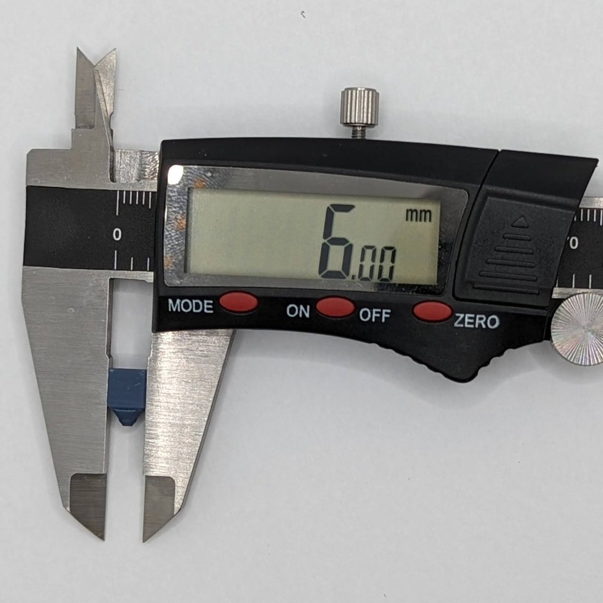
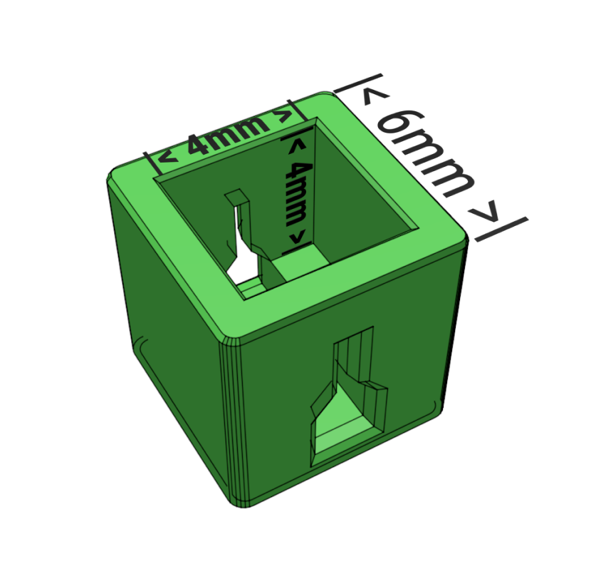
If you have a pair of digital calipers, snap off the 4 mm and 6 mm Boxes, to allow measuring all the boxes easier.
To measure the inside of each box:
- 6 mm box’s inside should measure 4 x 4 x 4 mm.
- 8 mm box’s inside should measure 6 x 6 x 6 mm.
- The walls will measure 0.98 mm.
 |
 |
Once you have reached dimensional accuracy you can now pay attention to the pillars.
The Pillars
The pillars are designed to do the following:
- Calibrate to tensile strength of most resins.
- Not all resins are designed to do the same thing, some will get less than 10/10.
- Help you understand the minimum tip size when doing your own supports, or printing pre-supported items.
- Your smallest support tip size should be 1 step larger (0.02mm) than any failed pillar.
- Example: If 0.14mm pillar failed. I should not use 0.16. The smallest support tip size would be 0.18mm with that resin.
- If you have 10/10 pillars (S Tier), at dimensional accuracy skip to the next chapter, you win!
- If you have 8/10 pillars (A Tier), at dimensional accuracy skip to the next chapter still very good!
- If you have 6/10 (B Tier) or under pillars, at dimensional accuracy, keep reading.
So you’re missing pillars?
- Make sure your resin is between 22 ºC and 30 ºC.
- Make sure your “wait before print” or Light-Off Delay is long enough for the resin and printer to come to full rest.
- If 2/s isn’t enough for your printer, try 3/s.
- Consider using a lift speed of no faster than 100 mm/m on the first stage of TSMC, or a retract speed of no faster than 200 mm/m on the first stage of TSMC and no faster than 60 mm/m on the second stage of retract.
- Make sure that you’re not lifting the build plate too much or too little.
- I’ve found that 6mm total of 3 mm + 3 mm of lift is plenty for 10″ printers.
- Maybe your resin is a highly flexible, casting or other specialty resin, designed for a very specific application there for has low tensile strength?
- Maybe you have an old 3D printer with massive pixels,or a scratched up and dirty LCD? Maybe you need to be ok with some loss of details? Boxes that measure 0.04 – 0.1 mm too big to achieve a level of tensile strength you’re after?
- Because of Boxes of Calibration’s unique design, you know exactly how much accuracy you’re choosing to give up for higher tensile strength.
- Play around with all of these settings to find your own perfect spot for your resin, printer and printing conditions. In the end, this is your printer, run it how you want!
Calibrated!
Once you’ve reached as many pillars as you can, at dimensional accuracy you have calibrated your resin to GOD tier! Save the resin profile in your slicer as “Boxes of Calibration”.
Perfecting Your Resin Prints
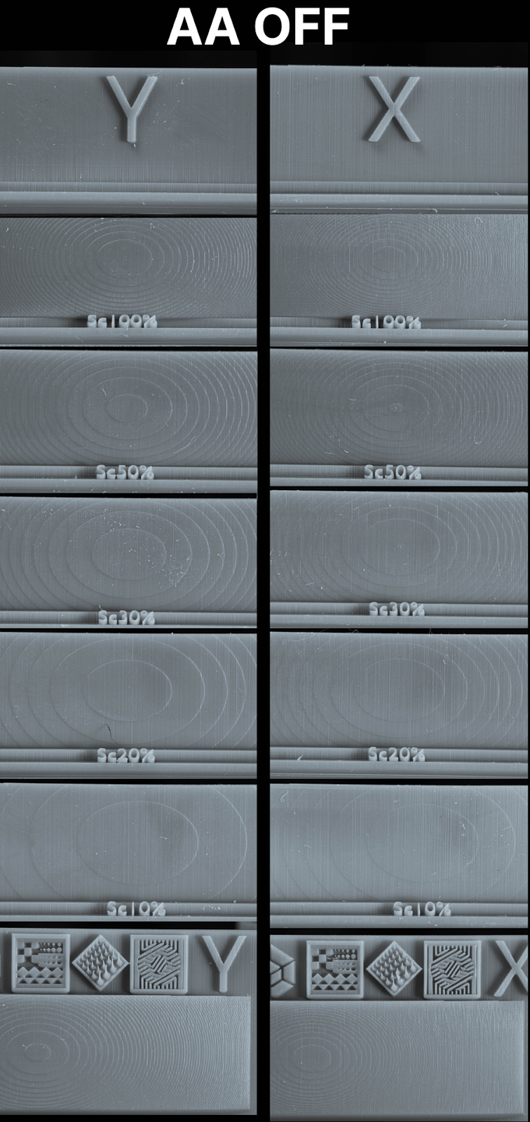
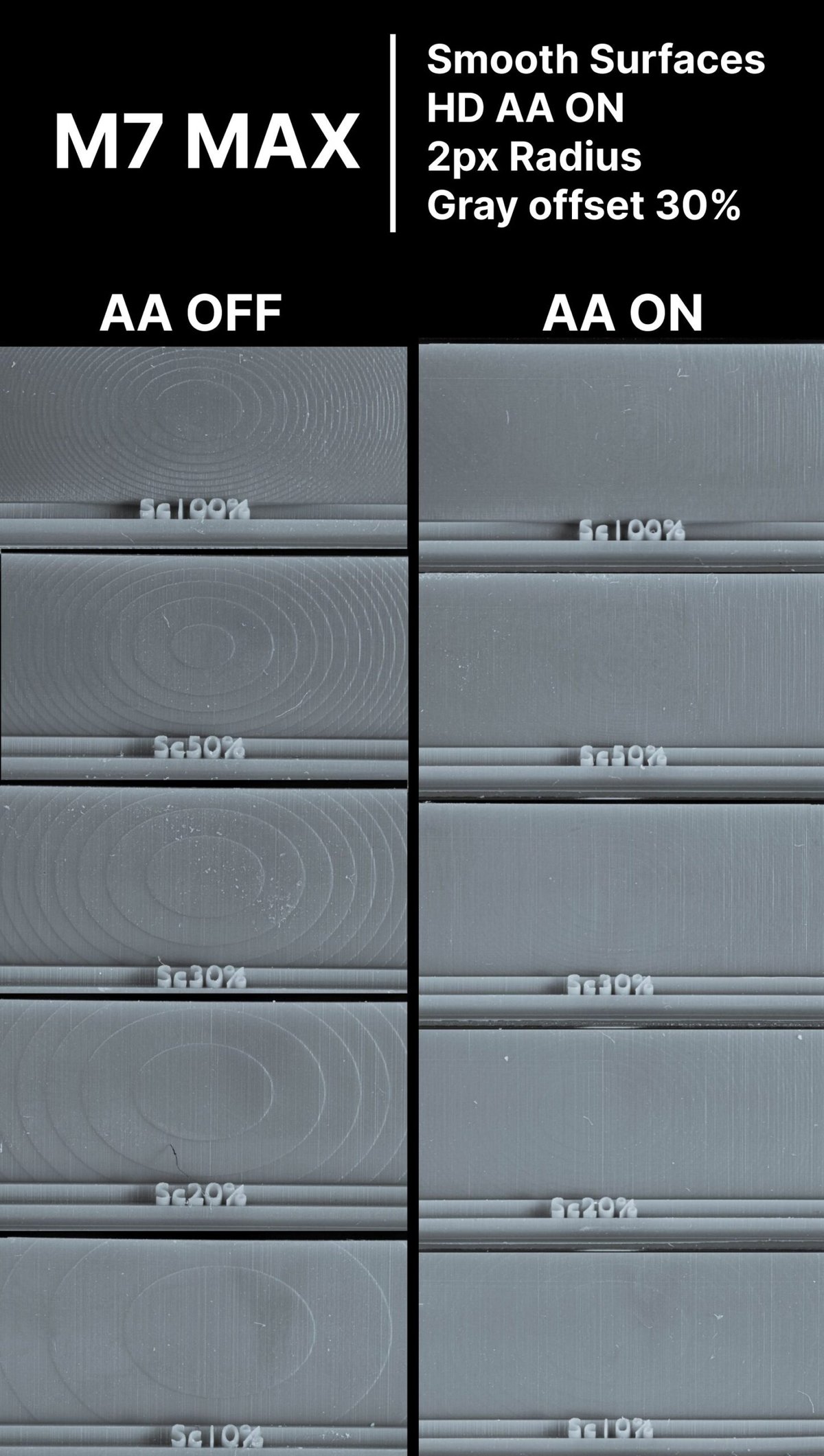
Anti-Aliasing
Remember, anti-aliasing is not used for calibration.Antialiasing (AA) is designed to smooth the surfaces of your 3D print by adding extra greyscale pixels on the curvature of the images that the 3D printer will display on the screen.
If you have an Elegoo printer, don’t use AA when using the .goo file format. It can cause some VERY serious issues (learn more).
What is shown below is the best setting for AA. Many other AA settings offered little to no difference, however this setting is magic.
Do your own test to validate, print with AA on and OFF then reach out to me on the Lychee Discord to share the results! DL the file here.
Lychee Slicer version 5.0 and on:
- Anti-aliasing – Smooth Surfaces
- Radius 2 px
- Grey Offset 0%
- High Definition Anti Aliasing ON
- Anti-aliasing on Supports Off
Testing on the M7 Pro:
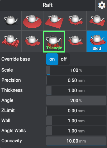
Rafts
Minimum .7 mm thickness
You have many types of rafts to choose from. What one you choose is up to you as long as you pick one. However I do recommend the “Sled” or “Line Triangle in Lychee”.
I’ll use the Triangle◼︎ raft for large bases or anything with a massive surface area on the build plate.
The Sled◼︎ raft is best for everything else. The lip makes it easy for the scraper to get under and pop the print off of the build plate.
Model Sizes
Now that your bed is level and calibrated, it’s time to apply it to the different sizes of models.
Small Models
Small prints are very forgiving. You can also get away with a lower burn in layer time. Often around 15-5 seconds.
Medium Models
Medium model settings will be used the most. They can be used for small to medium large prints. Add 4-8 seconds to your Burn-In UV exposure time.
Large Models
Larger objects come with issues of gravity and large cross sections increasing suction force – the pulling force your printer has to use to pull the model off of the FEP.
- Add ~10 seconds to your Burn-In UV exposure time.
- For thick models with a large cross section you will need to use 3/s LOD at a minimum. (Light Off Delay/Wait Before Print).
- If your printer allows independent “burn in” layer LOD , do 5 seconds.
- This only works on .goo or .prz.
- .ctb even if it has a separate LOD for the burn in layers, it will only use the LOD set on the normal layers.
- Always hollow large models if you can, more on hollowing to follow.
The Truth About 90% of Failures
If you followed this guide to this point, you’re in a minority. A minority that took the time to calibrate your printer and obtain some knowledge.
However, far too often I see failures where nothing is printed but the supports. More often missing an arm, leg or another feature. The #1 piece of advice I see given is… can you guess? “Increase the exposure time!”
If you can print the supports or half of the object, why can’t you print the rest of the model?
If you’re under-exposed would you not just have a blob on the FEP?
While “Increasing the exposure time” will eventually work. At the cost of finer details and resin. There is another option, simply increase the support!
And it can be simple, you can do this in a few ways:
- Add supports
- Make the (structural) support tips a little larger. Normally 10% is more than enough.
- A bit of both.
If you’re using Lychee Slicer, and you have the .lys or .slt file watch the video below for a fast and easy way to do this. For everyone else, keep reading and I’ll go over how I support models to get success even when using the most difficult resins on the planet.
Model Orientation
Watch the video below to become an orientation master!
Skyscraper Orientation Method
Pros
- Amazing precision and detail
- Less support overall
- Reduced Layer lines on hard surface modeling
Cons
- Longer print times
- Lots of supports on the surfaces towards the build plate
- Can sometimes not be possible unless you know how to alter a 3D file
Objective #1: Orientate so the surface you care about the most is at the top or sides of the print. Never put visible details you want to preserve facing the plate.
Objective #2: Orientate the model so that it supports itself. The object is your best support; use it. It’s best to look for V or Y shapes.
Objective #3: When dealing with a large flat surface, like a base. Add tilt to help build that flat surface over several passes (as long as it does not overly interfere with objective 1 and 2).
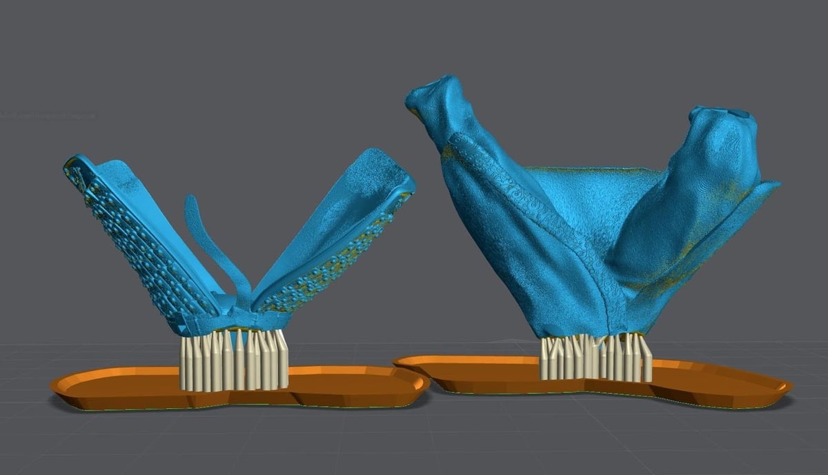
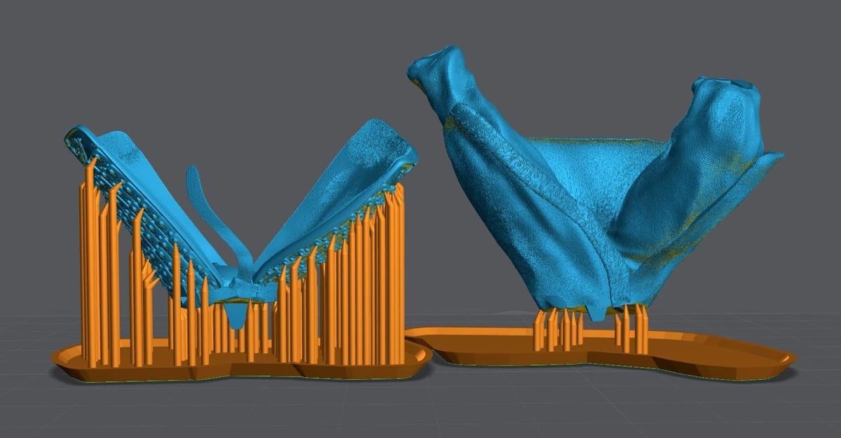
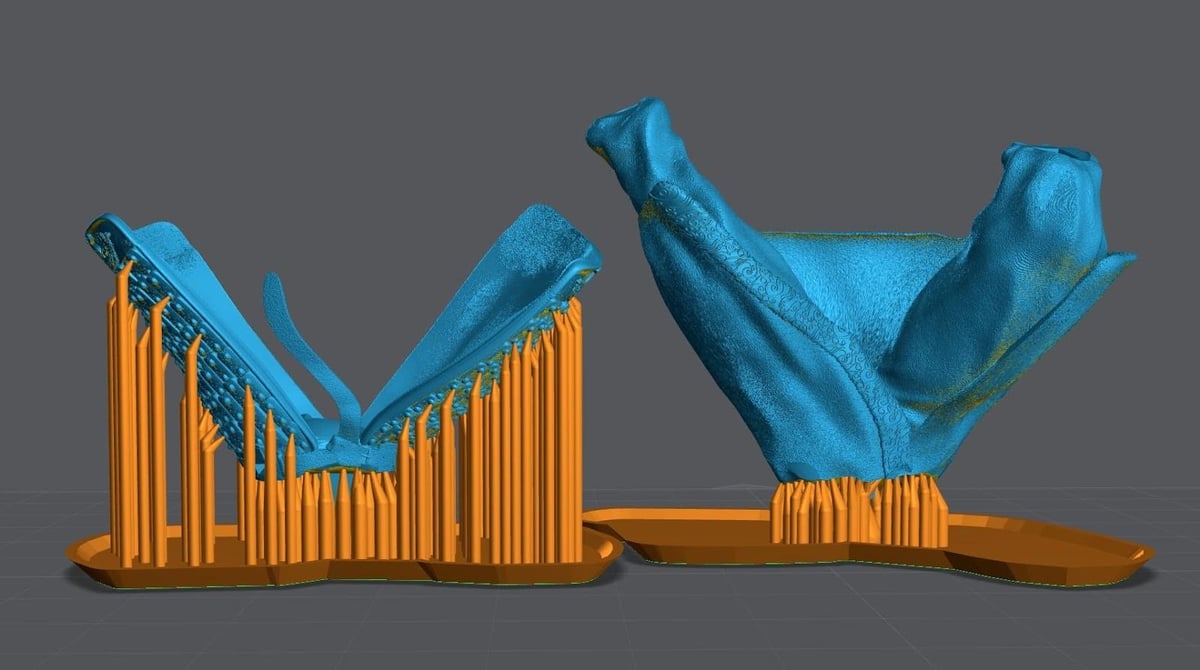
When Printing Bases
Rotate the base so that the part that will face the front is highest on the Z-Axis. How much you tilt the base is based on a few key factors:
- What type of resin are you using?
Some reins can get away with very little tilt and have limited pillowing. (Pillowing in what you see on the print on the Right in the picture below.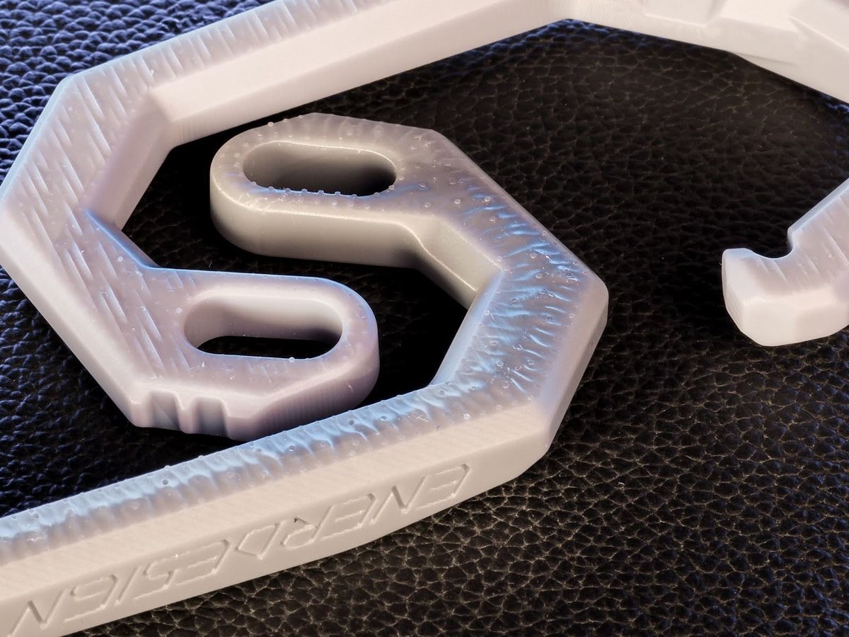
In this example both of these prints are printed at 30um, calibrated to Dimensional Accuracy and printed at the same angle. The only difference is the resin used. This is because not all resins are after the same end goal, for example: Pigment added to resin for color blocks UV light, the more pigments the more accurate the resin can be. But it will also be thick and brittle as Pigment makes a horrible poliomer.
Some resins are designed to be flexible or more durable. These types of resin always suffer with accuracy due to the properties of the fillers allowing the UV light to easily pass deeper into the resin creating accuracy issues.
- Is the base flat on the top or does it have a lot of other details?
The bottom of the base can always be sanded down. Don’t sacrifice details of the overall print by overly tilting if it could affect the end result. With this type of base it’s best to follow the Objective 1-3 above.
Traditional Orientation Method
Pros
- Shorter print times
- Can focus on reduced cross sections over all other objectives.
Cons
- 45-degree rule is subjective and often incorrect
- Supports end up on visible surfaces
- Lots of supports all over the model
- Tall supports that often are almost the height of the print requiring a lot of bracing
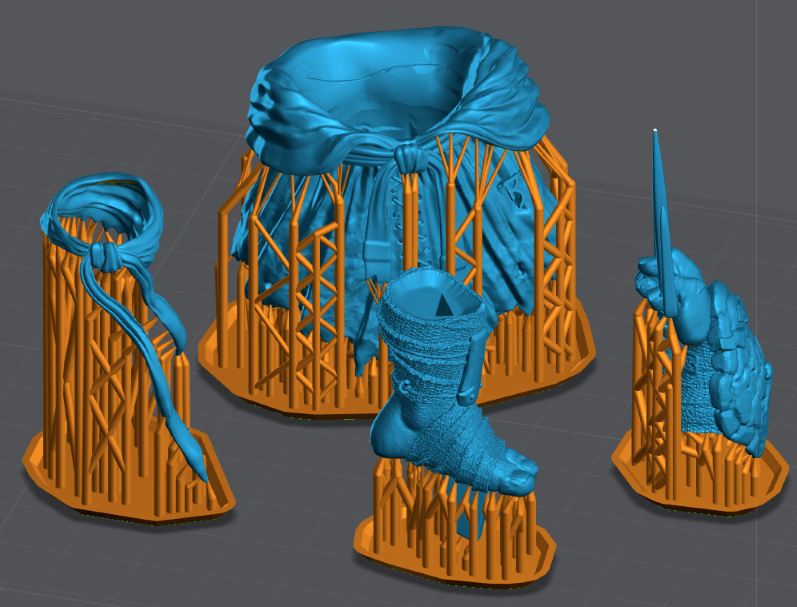
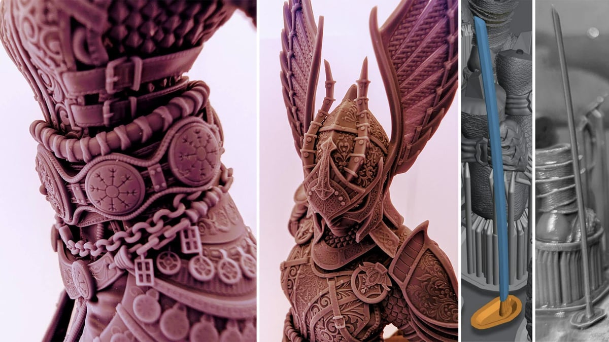
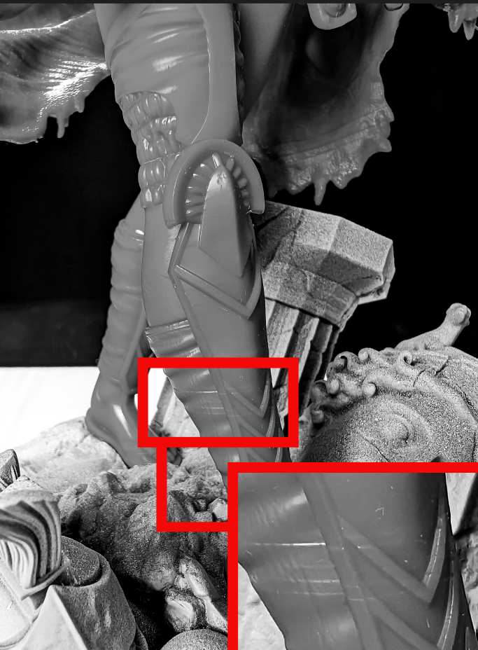
Traditional Supporting vs. Skyscraper Methods
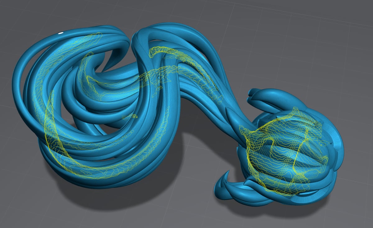
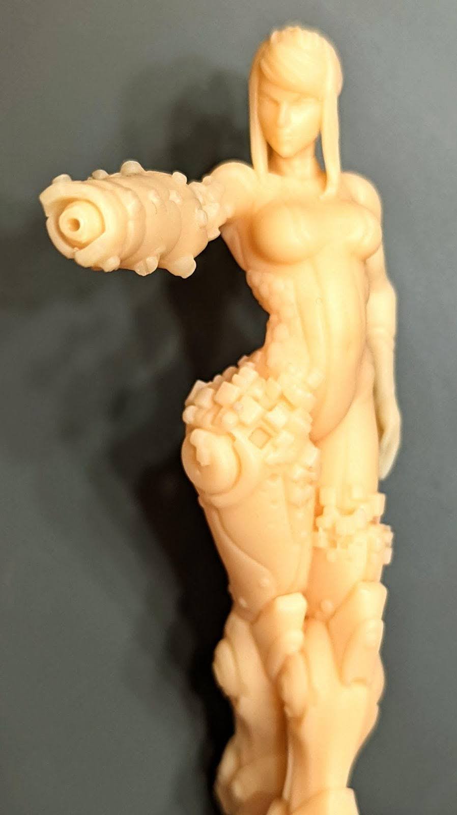
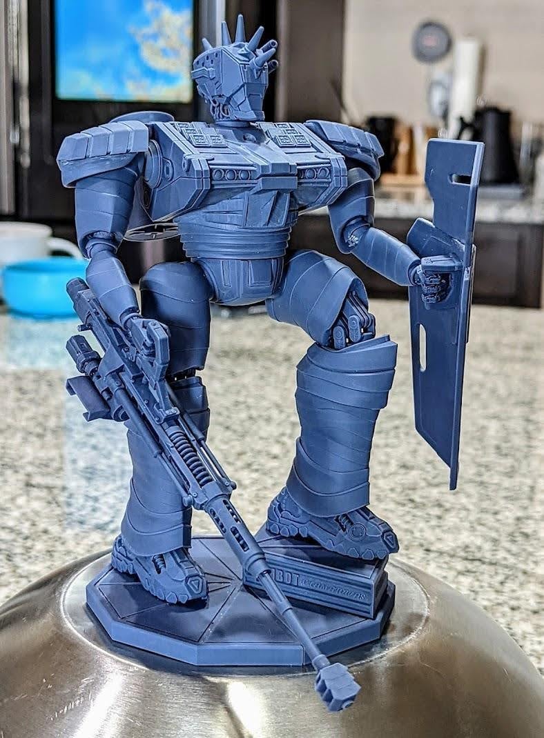
On the example below, supports will be on the exterior and final details of the model. As you can see there are supports on; back of the foot, blades and hand shield. The kilt and mask will have support damage facing up towards the viewer when assembled.
Example of my Skyscraper method: objects are facing up like a skyscraper to build on top of itself. Hollowing is used to reduce cross sections.
Supports are under folds that will point down in the completed mode and/or inside joints (the best place) that will be glued.
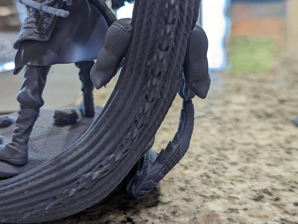
0.01 mm Tolerances
For some objects the only way to get accuracy you need is to print them straight up, Like a skyscraper. Below are some examples of objects with .01mm tolerances.
This moving track has over 90 links and was printed as a single part. Only possible using this Method and a very good resin. I used 100% Siraya-Tech Navy Gray.
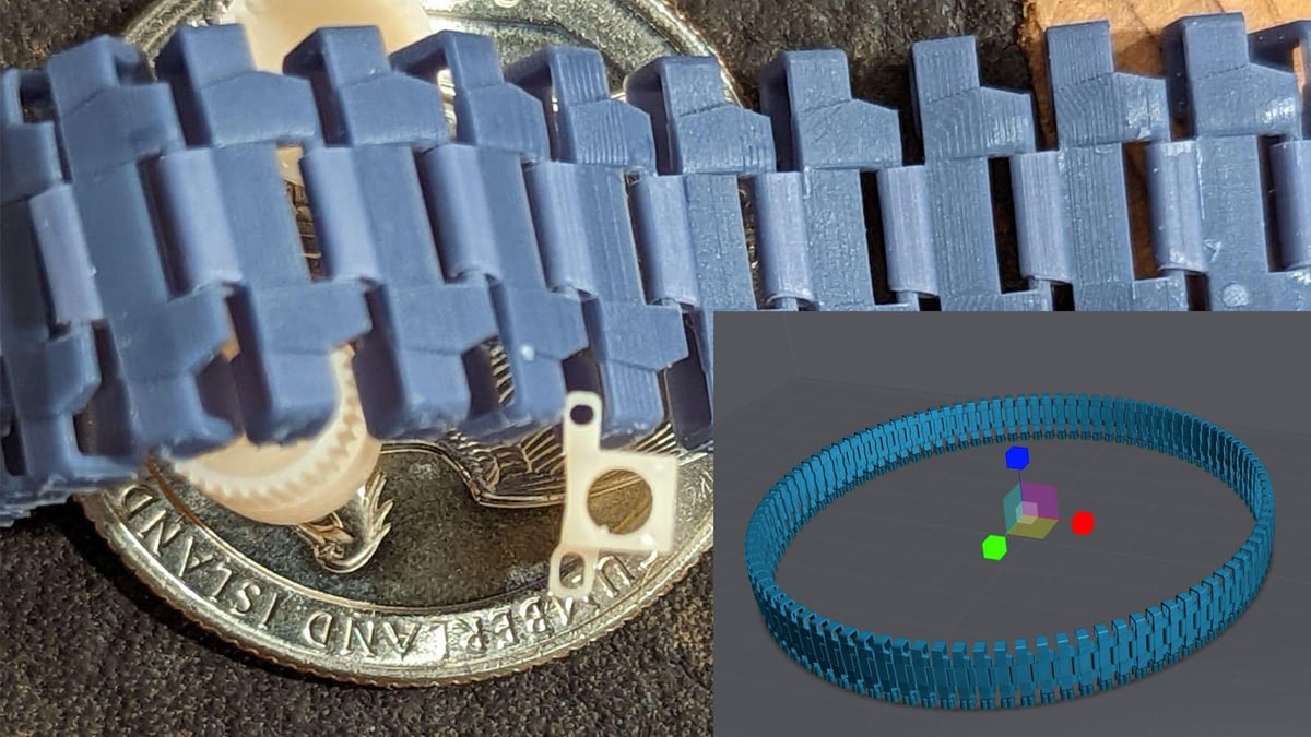
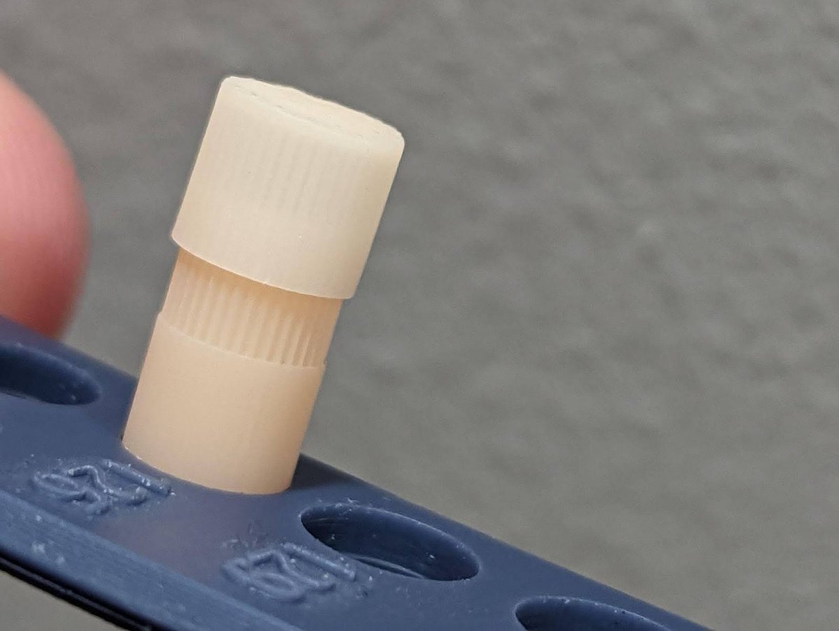
To visualize the track above I printed it as multiple parts. The size of the pin hole is 0.376mm and the pin is 0.354 mm. Thats .022mm total but I need a gap around the entire pin, that’s 0.011 tolerance! I also printed gear with a cap that has 0.008mm of tolerance.
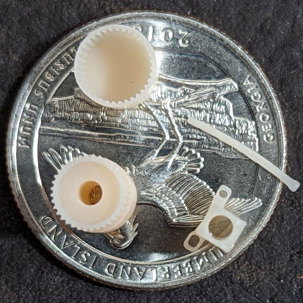
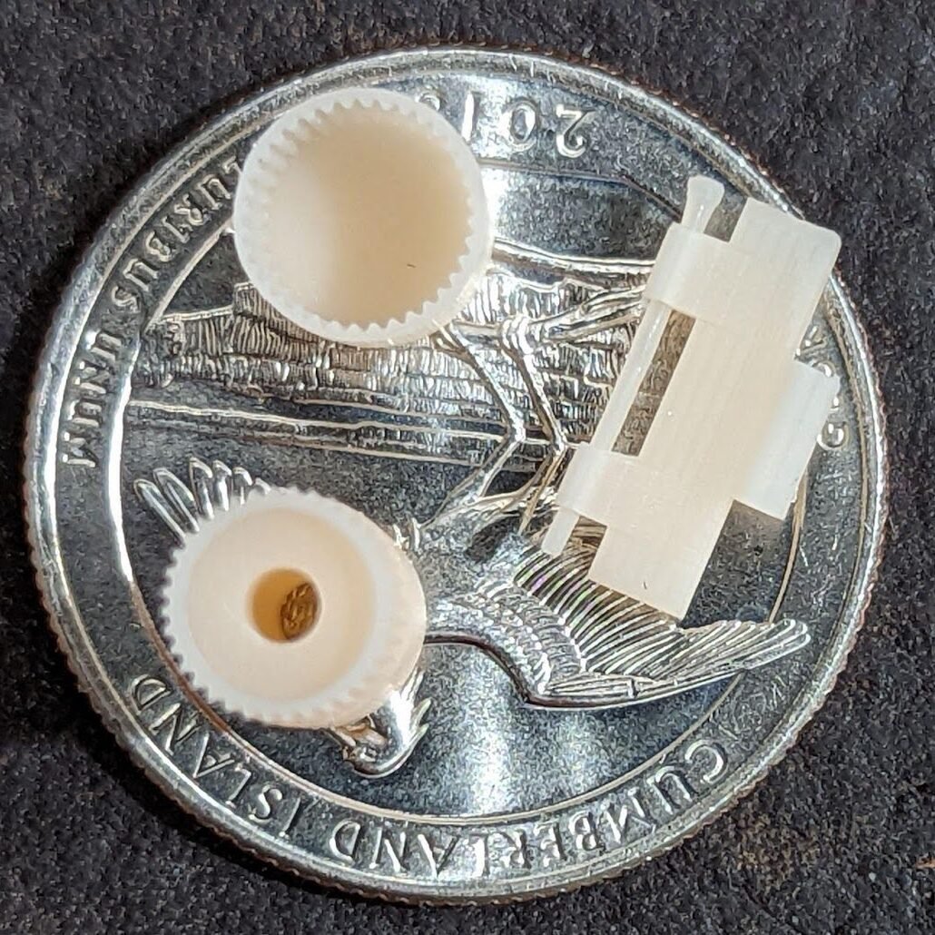
Notice the ridges compared to the ridges on a US Quarter.
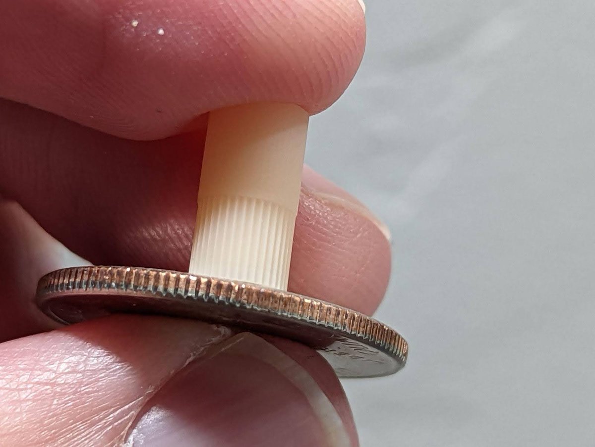
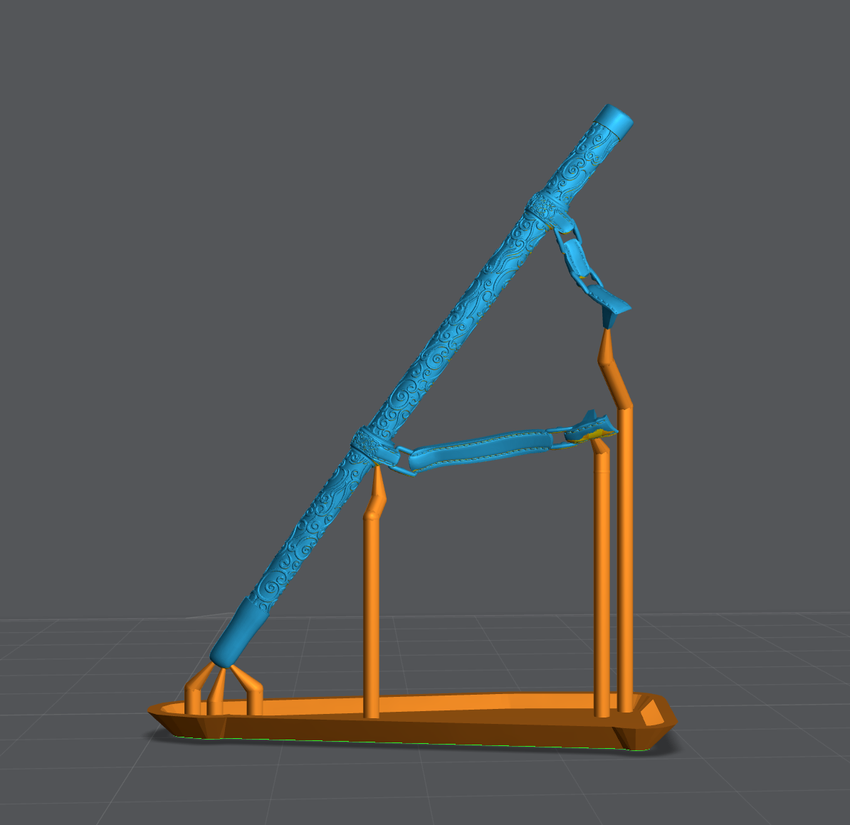
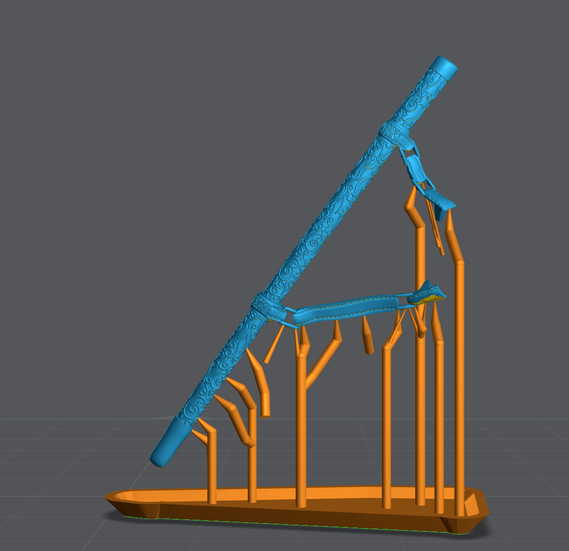
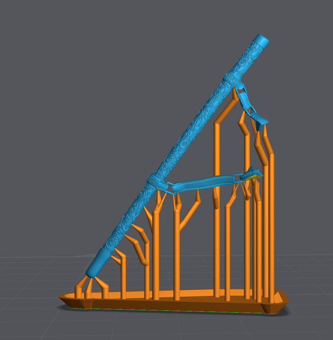
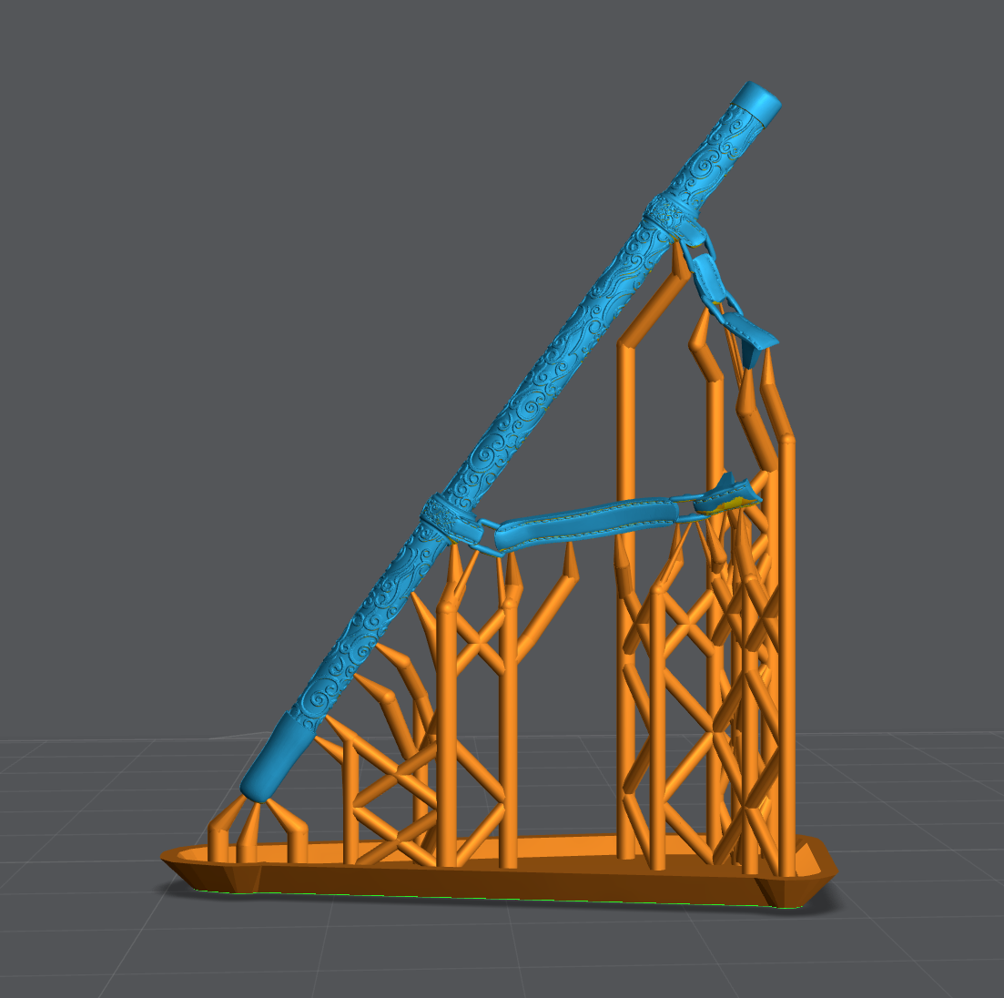
For miniatures this means more detail. This also works for tall thin objects like these swords.
Supporting
New to Support? See the video below!
There are four types of supports: structural, shape, detail, and bracing.
- Structural – Supports to hold the model to the build plate.
- These are often the largest tips and found at the bottom of any major island.
- Shape – These are the supports that maintain the shape of your object.
- You may find that your model will print with very few structural supports but your print will be warped. Adding “Shape” supports between structural supports will resolve this issue.
- Detail – These are your smallest tip sizes, used to support small islands that lead to fine details of a model.
- Don’t place a support on every island. If the island is under 4 or less layers or smaller than your support tip, you will often cause more damage adding a support then leaving it alone.
- Bracing – Used to keep anything from shifting side to side during the print.
- Just as bracings are used between support shafts to keep them from shifting. Bracing supports also need to be used to keep your entire model from shifting during the print.
It’s important to understand, once you have your printer dialed in for Burn-in and Normal layer exposure. Over 95% of print failures are a result of bad supports, NOT bad printer settings.
When supporting, follow the same logic mentioned previously regarding model sizes. Small, Medium, and Large Models. These support profiles were developed to get the best shape, detail and print success using my Boxes Calibration tool.
J3D’s Support Settings
With Lychee Pro you can have an additional 3 Presets:
If you have Lychee Pro you can download and import my support settings.
Supporting Bases
Helpful tips: watch my video on Mastering Lychee Supports.
Watch my video on how I supported this base below:
Supporting Small Models
With Small models you can get away with:
- Entire works of art in a single print
- No heavy supports used at all.
- Almost no light supports needed to retain small details.
- No hollowing
Note that just because you’re printing a small model does not mean you can now use light supports. Medium supports are for keeping shape and holding your print to the build plate, light supports are only for keeping detail.
Mulan Sword Example, Modeled by Sephon.
The blade is not curved at the end, it just looks that way because of how the light passes through it. Mulan’s sword is so thin you can still see through it. Until it was cured it would fold over like a wet noodle. Yet the final product still has amazing detail and it kept its shape.
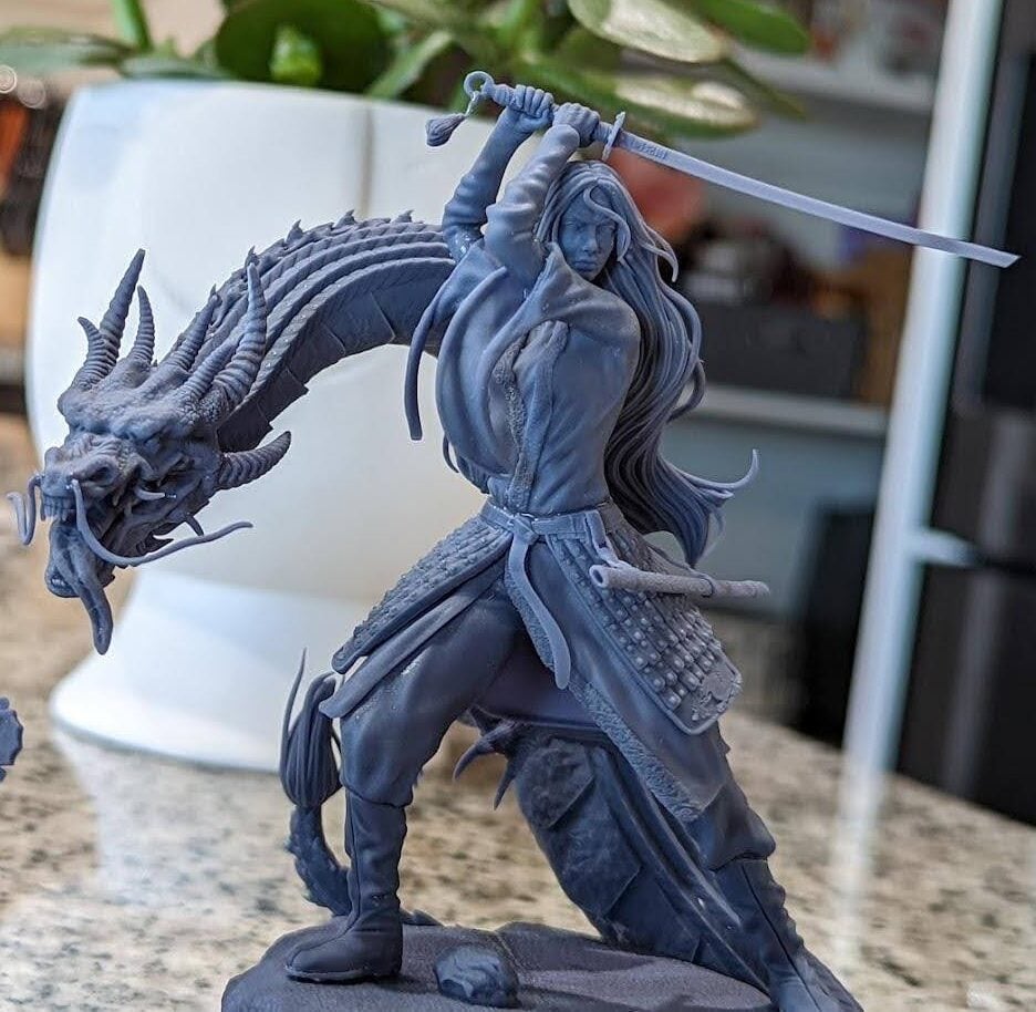
In this very small sword and sheath we have some extremely tiny details and a sword that’s under 1 mm thick. Using these settings such prints are very possible.
Supporting Medium Models
With Medium models you can get away with:
- Entire works of art in a single print
- One heavy support per model or major outcrop.
- No hollowing on thinner objects
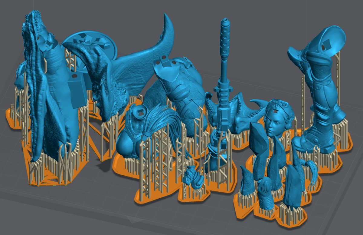
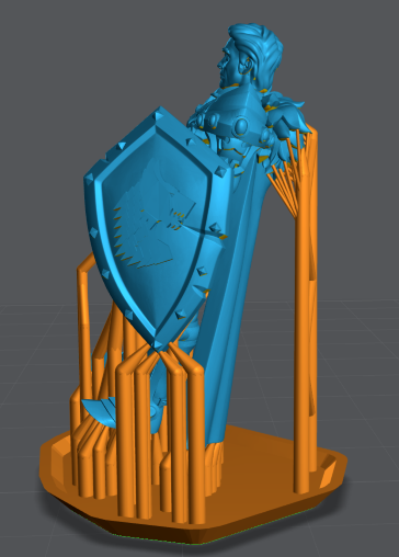
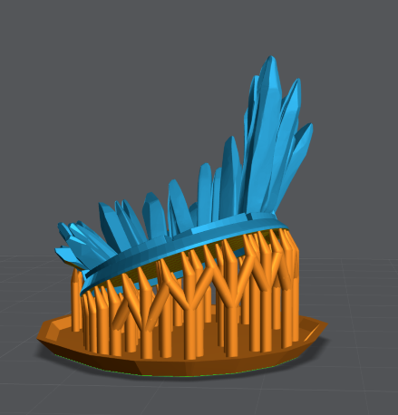
Warrior Example
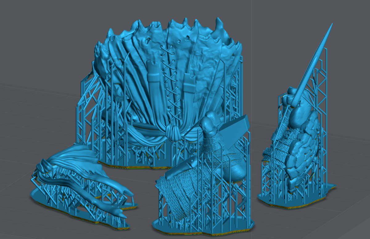
In this example of two medium models. You can see the use of the Skyscraper method in play. Pay close attention to the average direction of the crystals, shield and cloak.
Also notices how MANY medium supports are used to preserve the shape of the base. Think of a reverse bed of nails: the more nails the less pressure. There are no heavy supports used. Mini supports used to keep the details of the cloak.
Also pay close attention to the tip of the shield. Always support downward facing tips on multiple sides.
Surface Structure
If you’re trying to preserve the shape of an edge or surface. Place the supports right up to, but not over the edge.
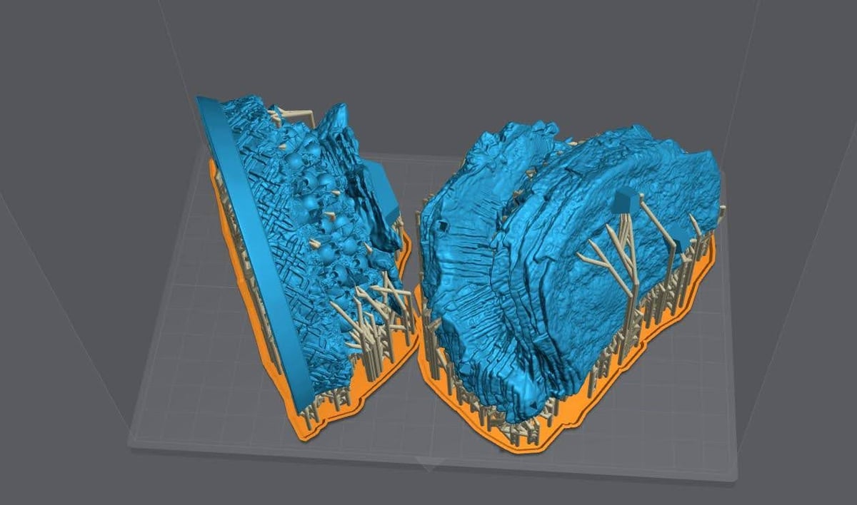
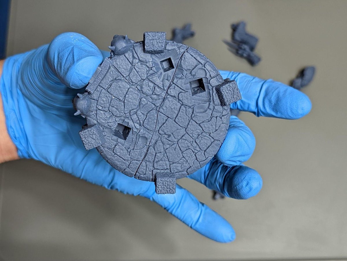
In this example of the base for the TMNT statue I have a complex surface that will be joined to another just as complex. I added a large amount of medium supports with light supports on smaller details like little outcrops in the rocks.
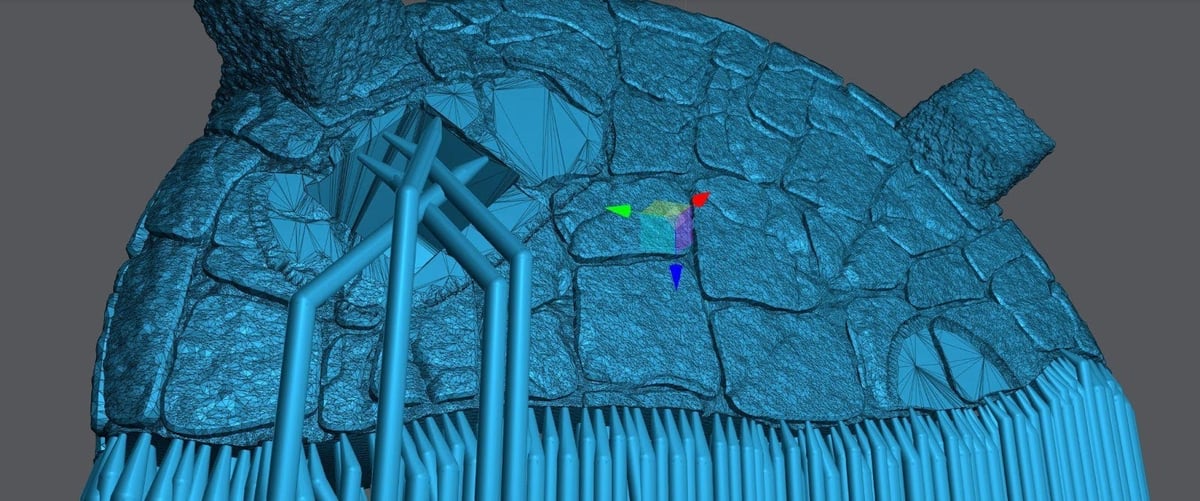
Result before any sanding. I’m holding it with 2 fingers to show I’m not applying pressure to the model, see how there is no stress on the glove.
Mulan Pants Example
The Skyscraper method at work, with the belt and legs.
Supporting Large Models
With large models you can get away with:
- Nothing, these suck.
- Hollow always, unless you have a technical reason not to.
- For models with a massive cross section increase your light off delay by 3 seconds.
- Hollowing may remove the need to add additional light off delay.
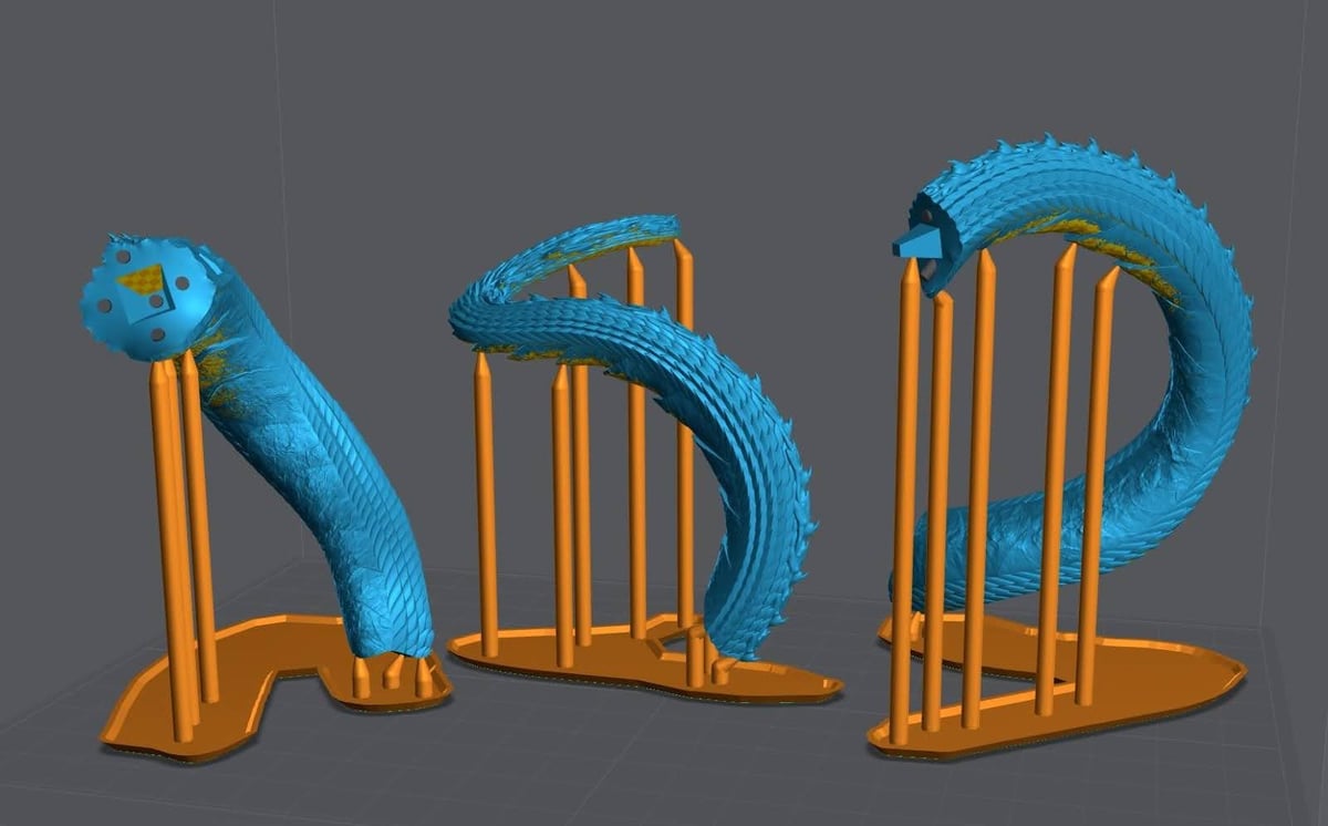
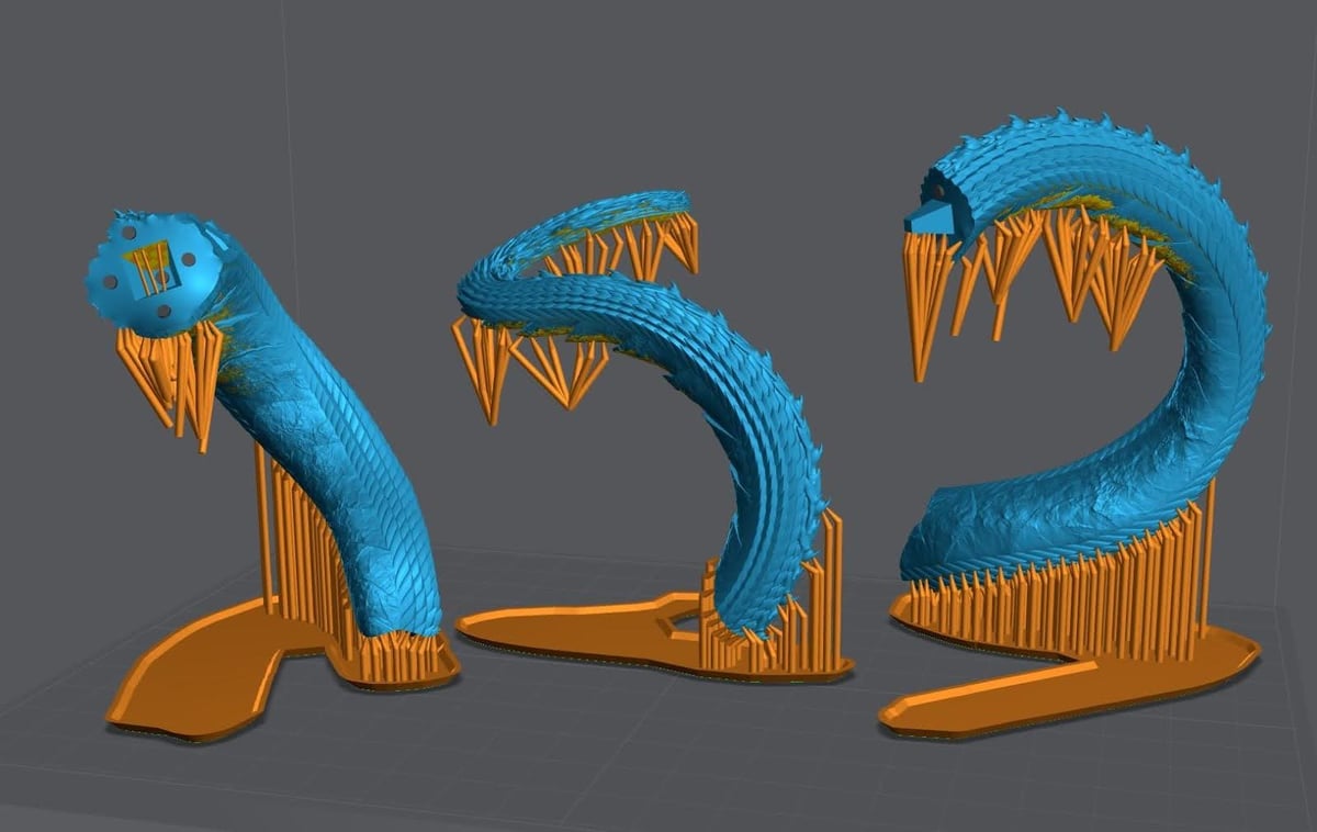
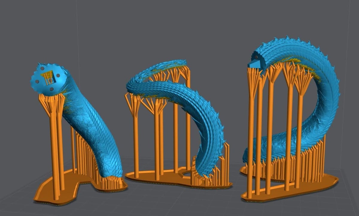
Mulan Dragon Example
F22 Example
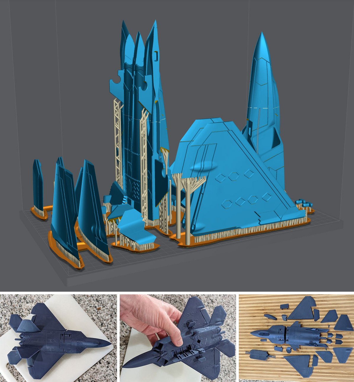
Hollowing
I highly recommend watching the video below:
If you can hollow, you should hollow. Just don’t forget to add drain holes in locations you won’t see in the finished model.
Pros
- Saves you money, the larger the model the more you save.
- Reduces suction, better quality prints and less failures.
- Reduces cross sections, better quality prints and less failures.
- Reduces the weight of the model, removing stress on your supports.
- Depending on your model can increase its stability on the shelf.
Cons
- Not placing drain holes at the lowest sections will lead to suction cups. Suction cups will likely cause print failures.
- Badly placed drain holes can make post processing difficult.
- Time to allow the model to correctly drain before removal of the build plate. (If you care to save money)
- If you don’t clean properly resin can and will push itself out of the drain holes during the curing process damaging your cure surface and the model.
- Depending on your model can reduce its stability on the shelf.
- If you forget to add drain holes, the gasses will cause your model to explode. Sometimes with enough force to throw uncured resin 20+ feet.
- Internal supports may be required.
Hollowing Settings
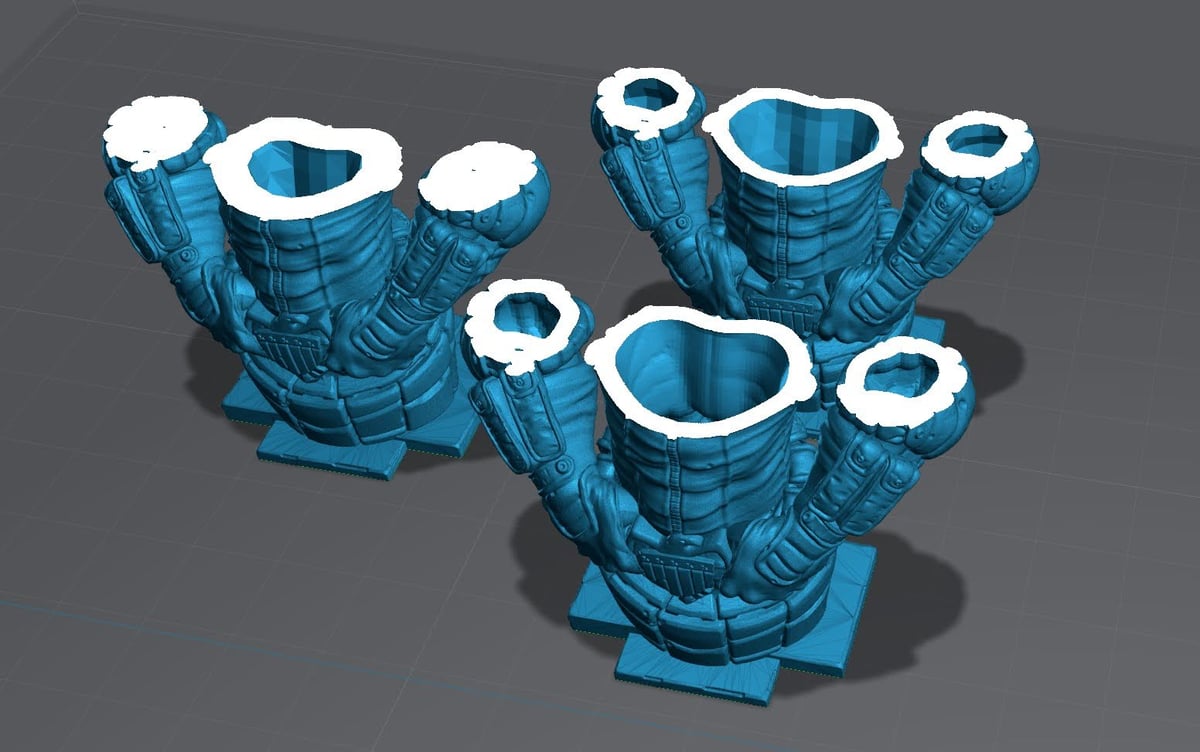
Thickness: How thick the wall is.
In the example above the bust on the left is at 2 mm, the busts on the right are at 1.8 mm.
Quality: How many polygons are going to make up the inner walls of your model. The more polygons the higher the quality but this comes at a cost.
In the example above the back of the bust is at a quality of 1 (min). The front bust is at 4 (max)
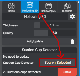
Suction Cups
Not to be confused with peel force or cross sections. Suction Cups are created when you have a void.
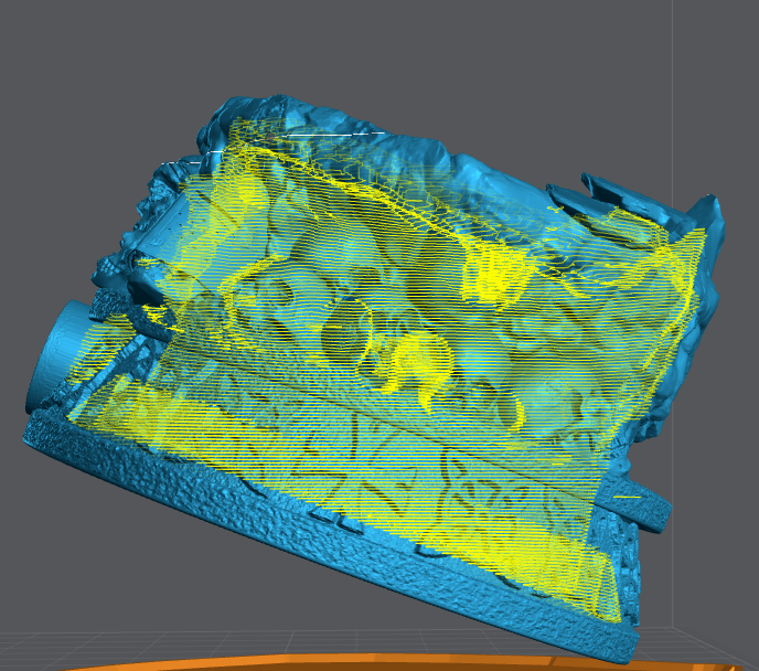
In the example above, I used Lychee Suction Cup Detector. Available in the Pro version to highlight the in this print in yellow. If you don’t have Lycee Pro you can use 3D Builder – Microsoft Apps. Remember that every void is a suction cup and will need to be addressed if they are too large.
To prevent suction cups, you need to place a drain hole in the lowest part possible. Adding holes as the print moves up will encourage good resin flow.
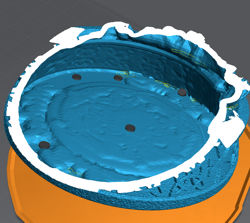
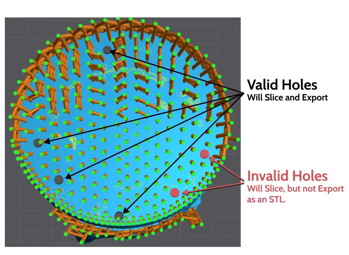
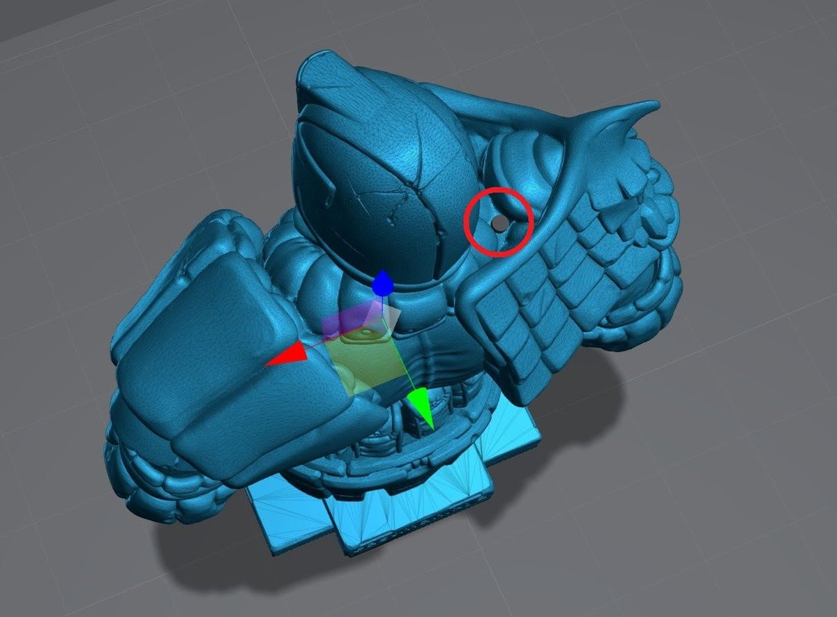
Some holes will be red this sometimes means that it’s against too much geometry and Lychee can’t export it. If you try and save this file as a .stl the two red holes won’t be added.
On the top of many models will have Natural Suction Cups. Not all of these can be resolved, however, if you’re hollowing, a simple hole into the main chamber should work.
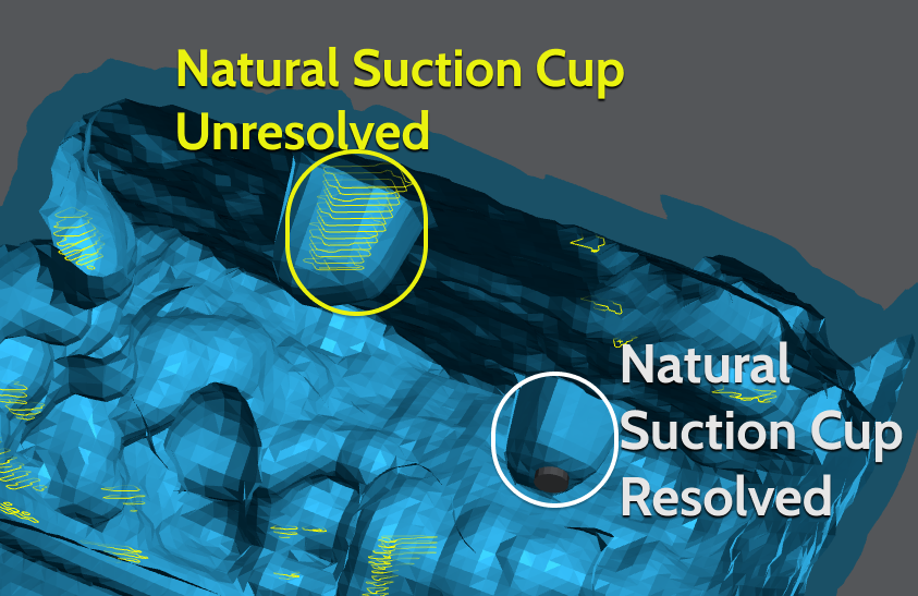
Smaller suction cups, the ones you see in Yellow are ok. They won’t affect the print enough to cause any damage or lower success.
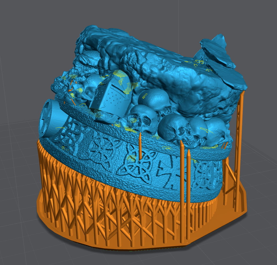
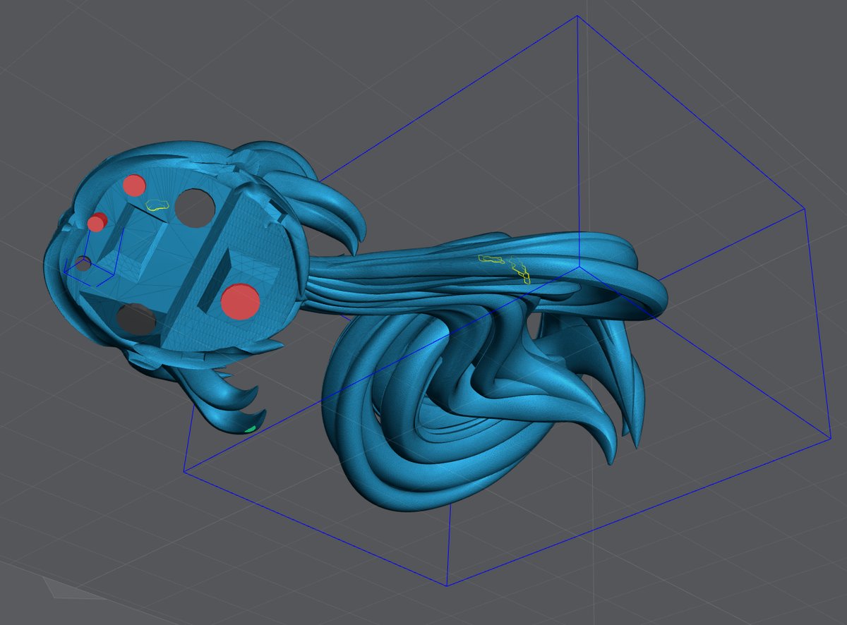
Blockers
Where a drain hole can’t be used, a blocker might be an option. Blockers only Block (prevent) hollowing. This means if the suction cup is created due to the shape of the model a hole must be used.
Blockers can also be very useful in removing resin traps. This is where you have a part of the model that’s large enough to be hollowed, but is surrounded by areas that are not.
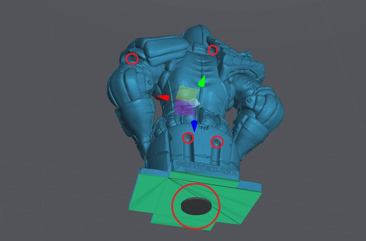
A few well-placed Blockers, the blue box◼︎, and holes, the Red◼︎ and Black◼︎ cylinders, removed almost all the suction cups. The suction cup in the back could not be resolved with a blocker because it’s a void in the geometry. Only a hole can resolve this. However it’s too small to cause any issues.
Drain Holes
Drain holes are needed to allow the resin to escape from the hollows parts of your model. I typically use as many as I can and I try to keep them over 2 mm, but the model will dictate.
Always place them in an area that can’t be noticed, or is difficult to notice. Always try and place 2 or more, at least one near the top of the model to allow draining during printing.
Drain holes need to be deep enough and/or angled to penetrate the wall of the model, but don’t come out the other side.
Hollowing On the Plate
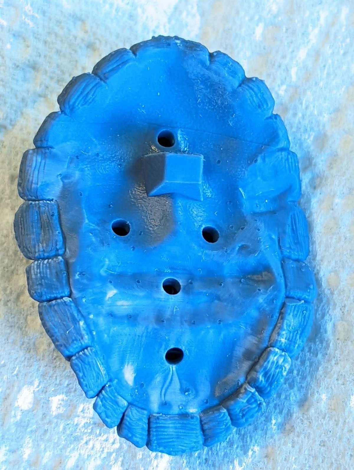
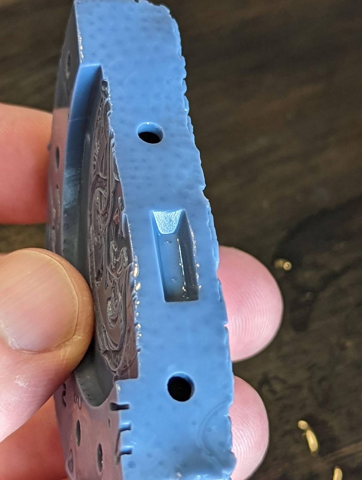
Some models are best built right onto the build plate but you still want to hollow them. This is difficult because the bottom hold won’t drain till after it’s been removed from the build plate. The trick is getting a minimum of 2 holes as close to the top of the print without causing any damage.
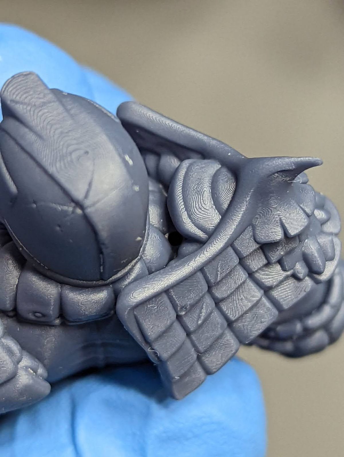
In this example I’ve snuck 5 drain holes into a single print model. Models that are done in one print are more difficult because you have no seams to hide the holes. This is where I find places that will be covered in shadows.
Here is the end result. Pictures taken under bright light and 4x magnification.
Internal supports
For larger objects you will need to add Internal supports.
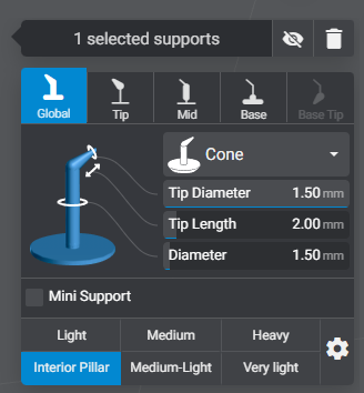
With Lychee Pro you can have up to 6 support profiles. I highly suggest making one of them an Interior Pillar.
If you’re using another slicer or the Free version of Lychee modify my heavy support to have a 1.5 mm shaft and 1.5 mm tip. This way the entire support is now a pillar.
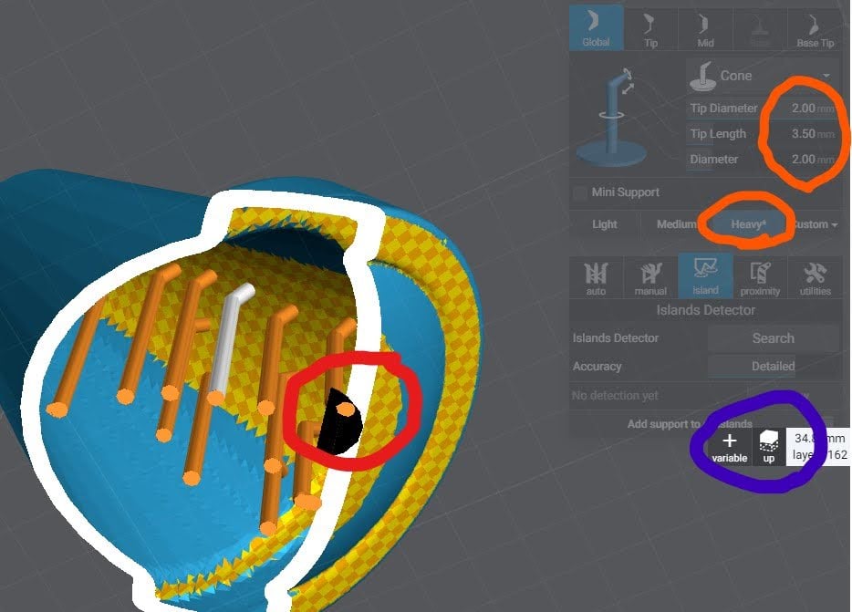
Next change the view so that you’re looking up under the model. There is a toggle on the layer slider.
Now you will support the inside of the model much but with far less support but much larger.
The objective here is to add some support on any large islands but not to small islands.
Finally support the “ceiling”, think of Dwarven or Roman architecture.
Printing on the Plate
I choose to build directly on the plate when I have an object that needs or can be perfectly flat on the surface that is against the plate.
Pros
- No supports needed
- low chance of failure
- Perfectly flat surface
- Great for printing smaller machine parts.
Cons
- Elephant’s foot. (Some slicers like Lychee Pro have features to help reduce/remove this)
- These sub $20,000 printers are not perfectly accurate on layering. You can suffer from layer crushing.
- Can be hard to remove from the plate.
- Hollowing can be difficult. This is because drain holes can’t be placed on the bottom layers.
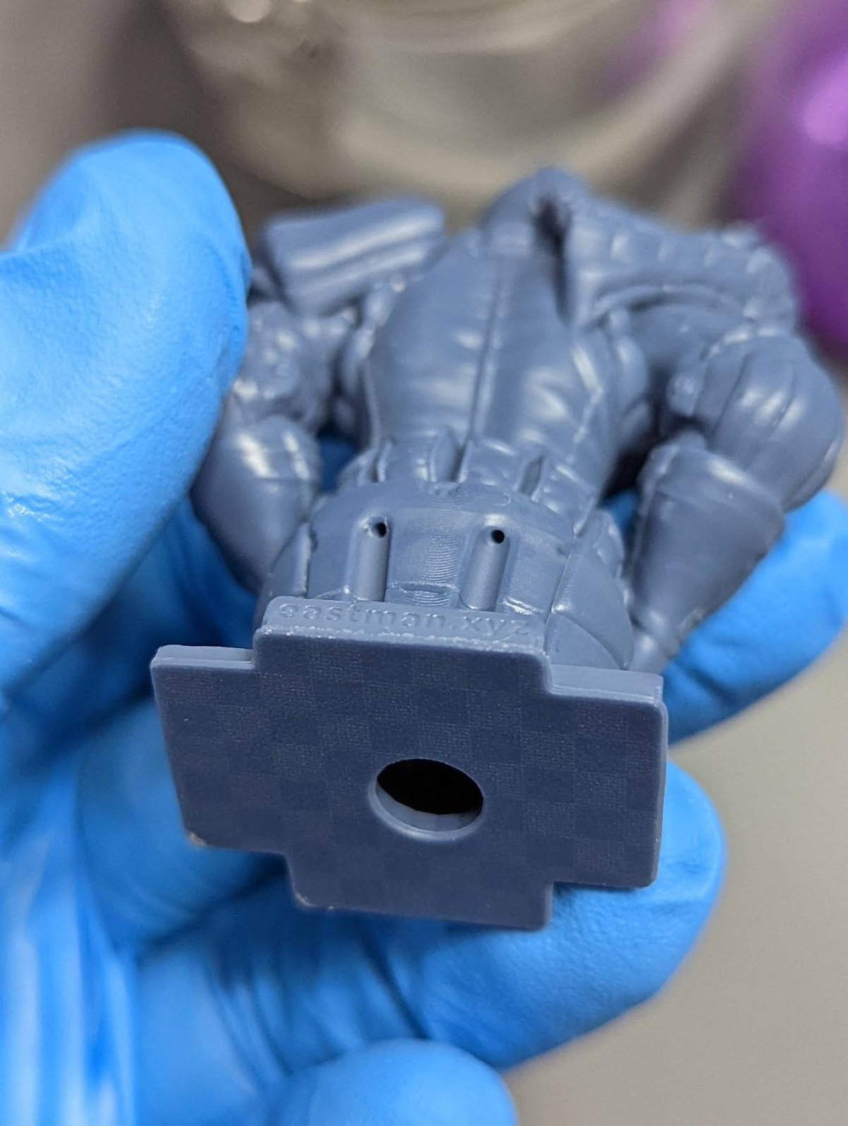
Option 1: Build in Raft
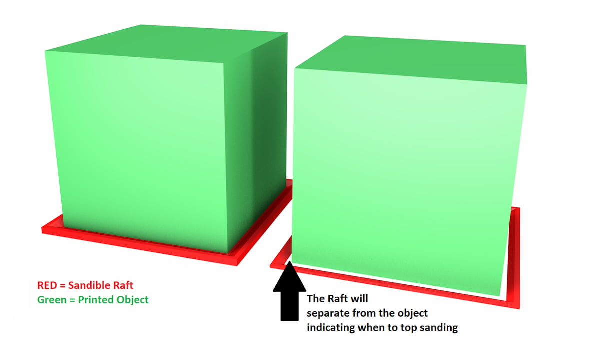
If you can edit the 3D file, you can also add a raft with raised edges that move away from the print. This Raft will absorb the Burn-In layers and make it easier to remove.
The raised edges will act as a sanding guide to make sure you both sand the print evenly and that you don’t over sand.
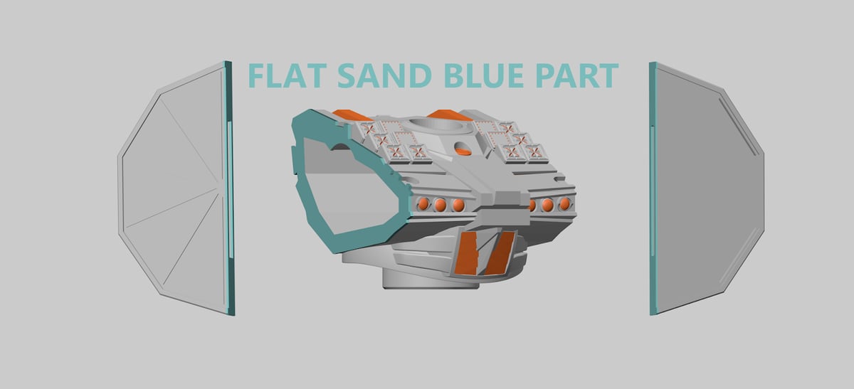
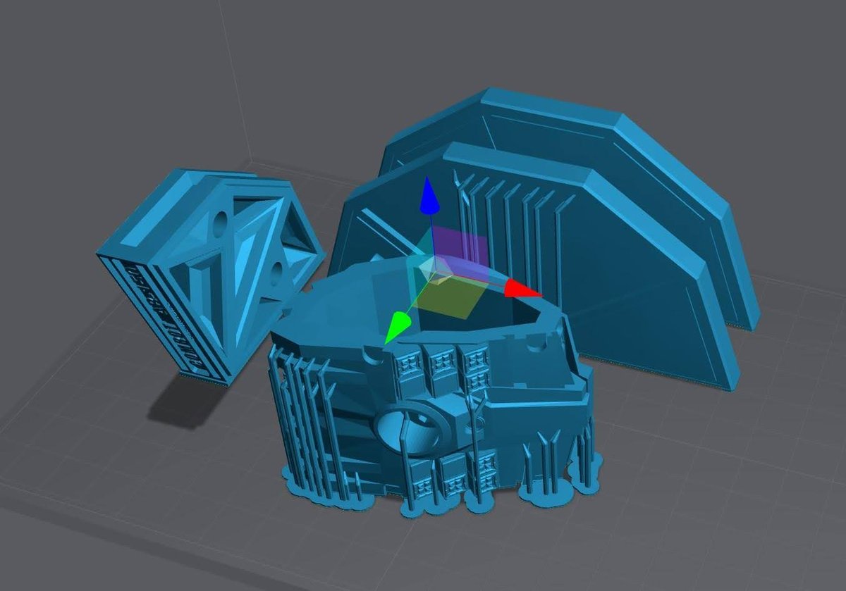
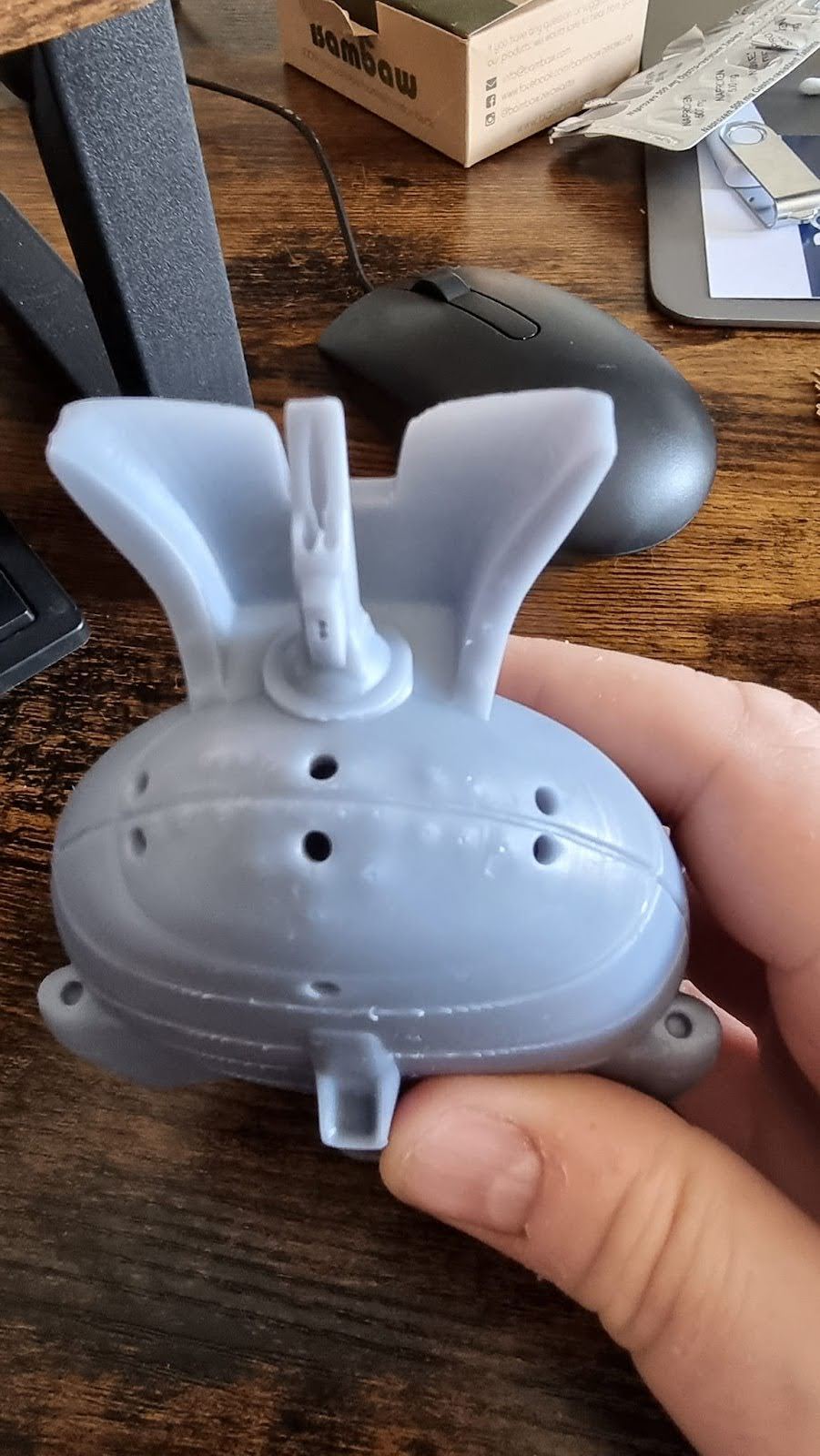
In this example I have 4 parts that will have a flat surface in the final product. Three parts to make up the base and the main chest that will have 2 side caps. All parts need to fit perfectly flat for the best result in the final product. Link to Robot model.
Option 2: Calibration to remove elephants foot and layer crushing
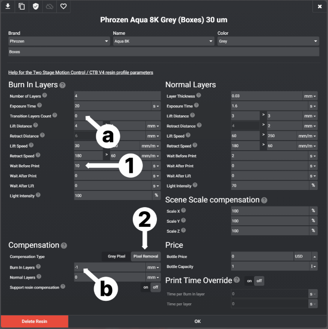
- Wait Before Print
- If your printer has a separate “Wait before print” for Burn in layers and Normal layers, set this to 7-12/s. This will allow the printer and resin to come to full rest before the resin is cured. This will greatly reduce Elephant’s Foot and even allow you to reduce your burn inlayers.
- If your printer does not have to “Wait Before Print” for Burn in layers and Normal layers (most do not) You can use UV tools to add in the pause.
- Pixel Removal Compensation
- It’s important to not use any Transition layers when using Compensation.
- Set a negative value to Burn In layers. Doing this will remove Xmm of pixels on the outside edges.
It will take a few test prints to find the correct balance of pixel removal vs exposure time. The goal is to remove the Elephant’s Foot while keeping enough material for good build plate adhesion.
To remove layer crushing see Build Plate Calibration.
Post Processing
Washing
You can see my process in the video below, or get a short run down here.
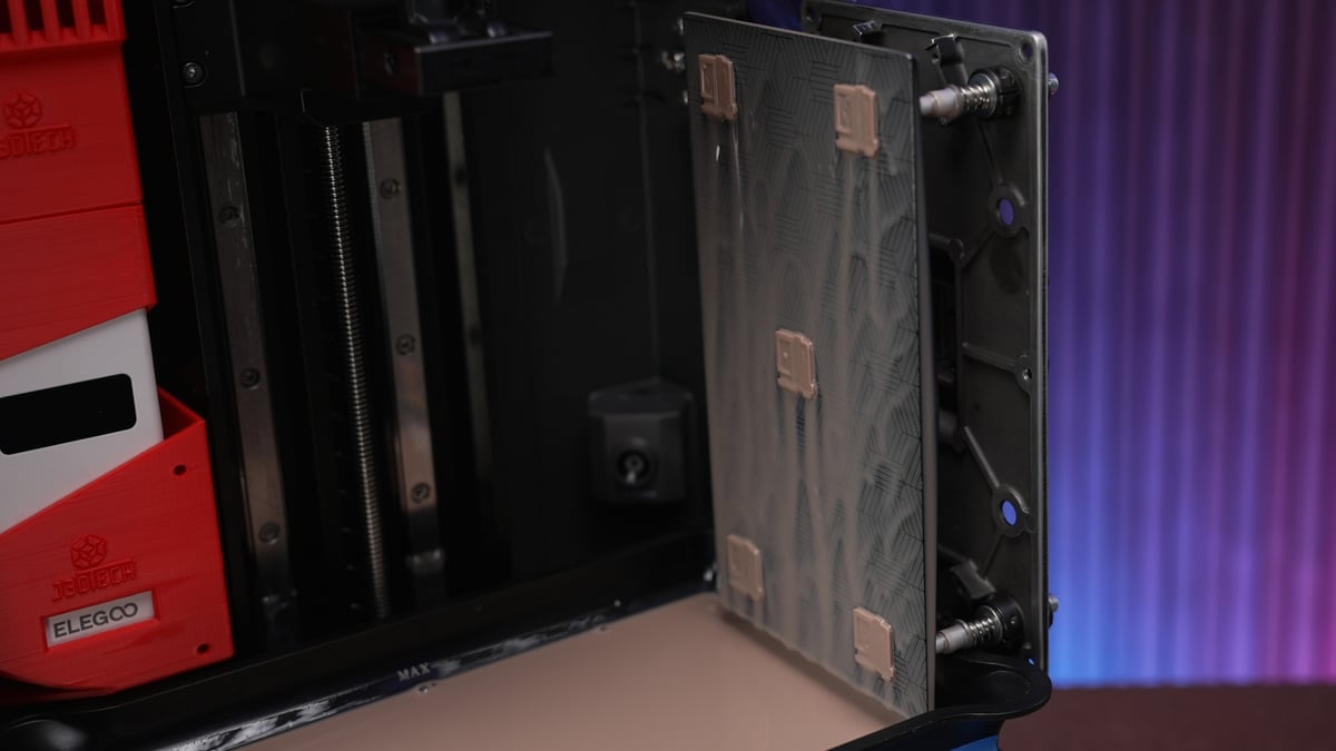
Build Plate Removal
Hold the build plate 90 degrees off of your surface to reduce the chances of throwing off your level. Use the scraper to get under the raft, and the model will pop right off.
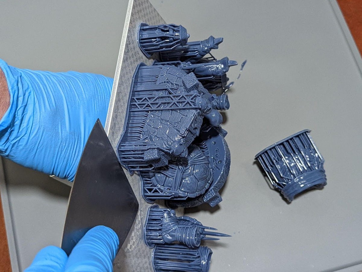
First Clean
I start with spraying IPA over my models right after I remove them from the plate to remove large collections of resin.
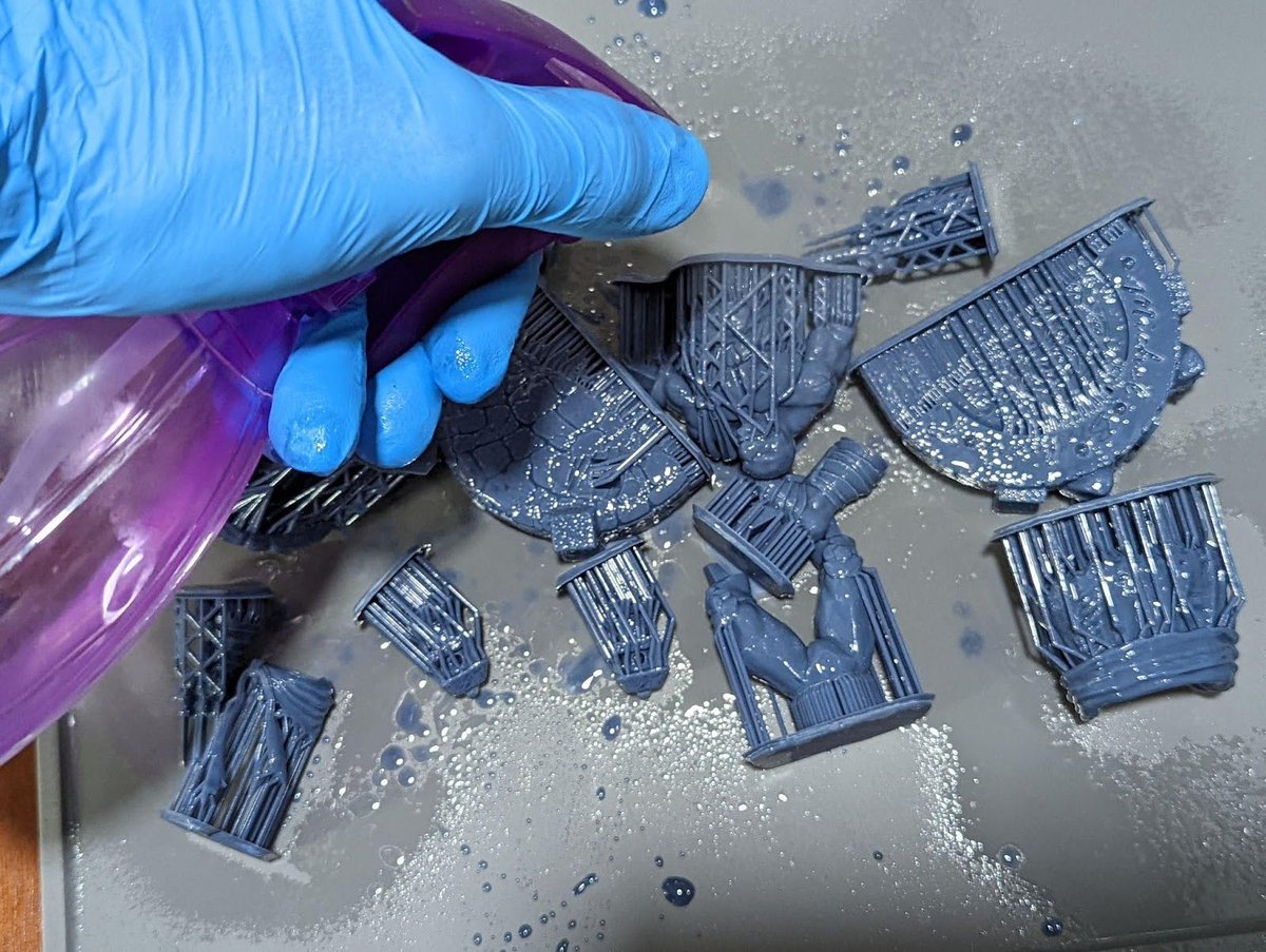
Second Clean
Dunk into a very dirty IPA, followed by another quick spray. Then I’ll lightly shake and knock off any extra fluid.
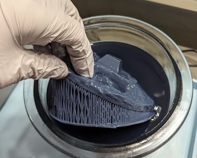
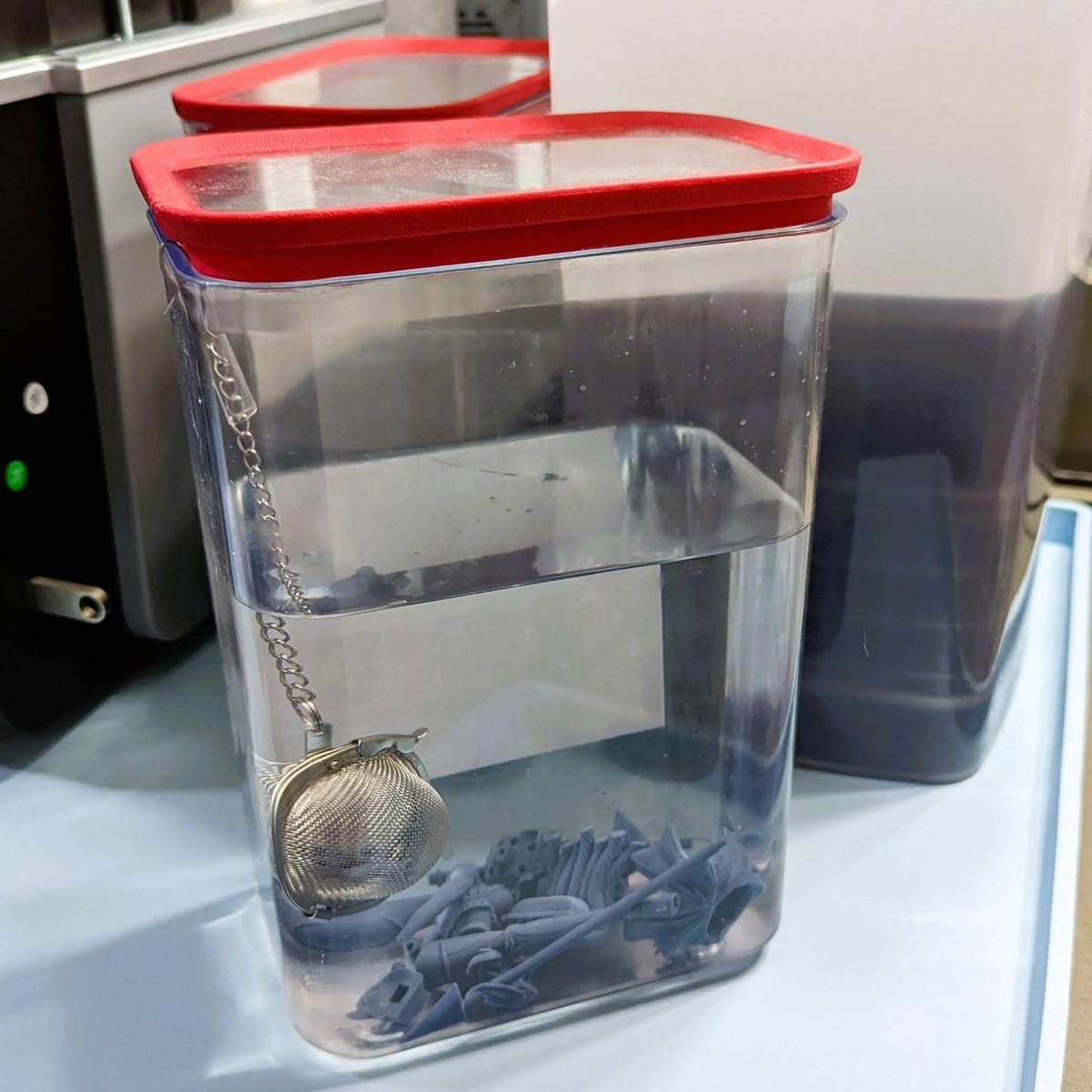
Third Clean
Now into the main IPA tank, where they will sit for 5-10 minutes. I no longer turn on the motor as I found it damages the models by banging them around and suturing in old IPA particles.
Instead, I let them sit, then at the end I’ll swish them in the upper layers of the tank.
Support Removal
I highly recommend you heat up the supports, then quickly remove them while they are hot. If you choose to do this using a heat source, you must wear a mask.
Hot Water Method
Put the print in a bucket of hot water and let it sit for about 30 seconds, then remove the supports. The result is pretty good, however, I don’t use or go into detail on this method as it has some major drawbacks.
- Some resins react with the water, especially if you leave them in there for too long.
- Heating the water adds time and more equipment as you don’t want to mix this process with your kitchen.
- Disposable of the now contaminated water. It cannot be dumped in the drain. Leave it in the sun and allow it to evaporate before dumping the build-up resin.
- Models wet with water take 6 times longer to dry than wet with IPA, even longer if hollow.
Heat Source Method
Here’s why I recommend the heat source method:
If the resin smokes, you overheated it. This will not ruin the model as by now you have removed 99% of all extra resin, but it will create toxic smoke.
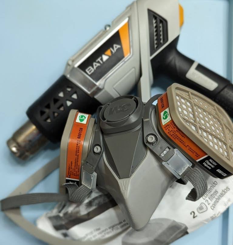
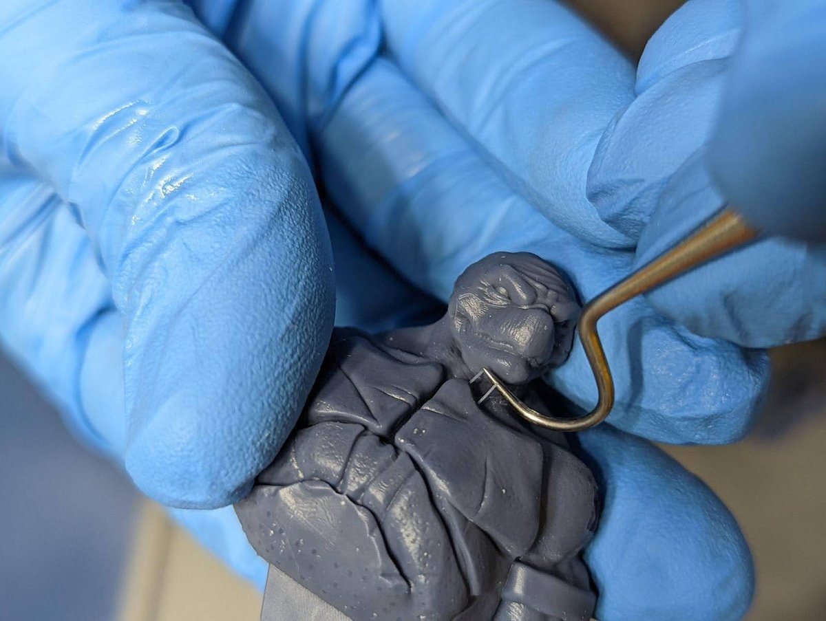
Remove any leftover supports using precision tools, I use this set of dental tools.
Final Steps
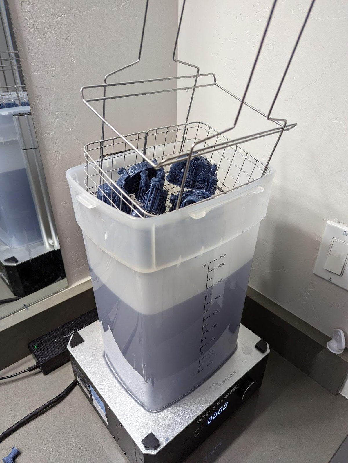
Fourth Clean
After the supports are removed, I run them for a final clean. This is not always necessary, but it can make a noticeable impact.
You can use an ultrasonic cleaner, All3DP recommends the Uniformation Ultrasonic Resin Cleaner.
Note: If you use an ultrasonic cleaner not intended for resin, do not use a heat function. Heated IPA must be in a very well-ventilated room, or users risk serious bodily harm.
The safer and cheaper method is to have another bucket with very clean IPA for the final dunk and wash. I’ll let my print sit in this for about 3 min.
Final Dry
Make sure your models are 1000000% dry before you cure. Let them sit for a very long time or use a mechanical tool like a heat gun to dry them off. Wear a mask when using heat guns around resin.
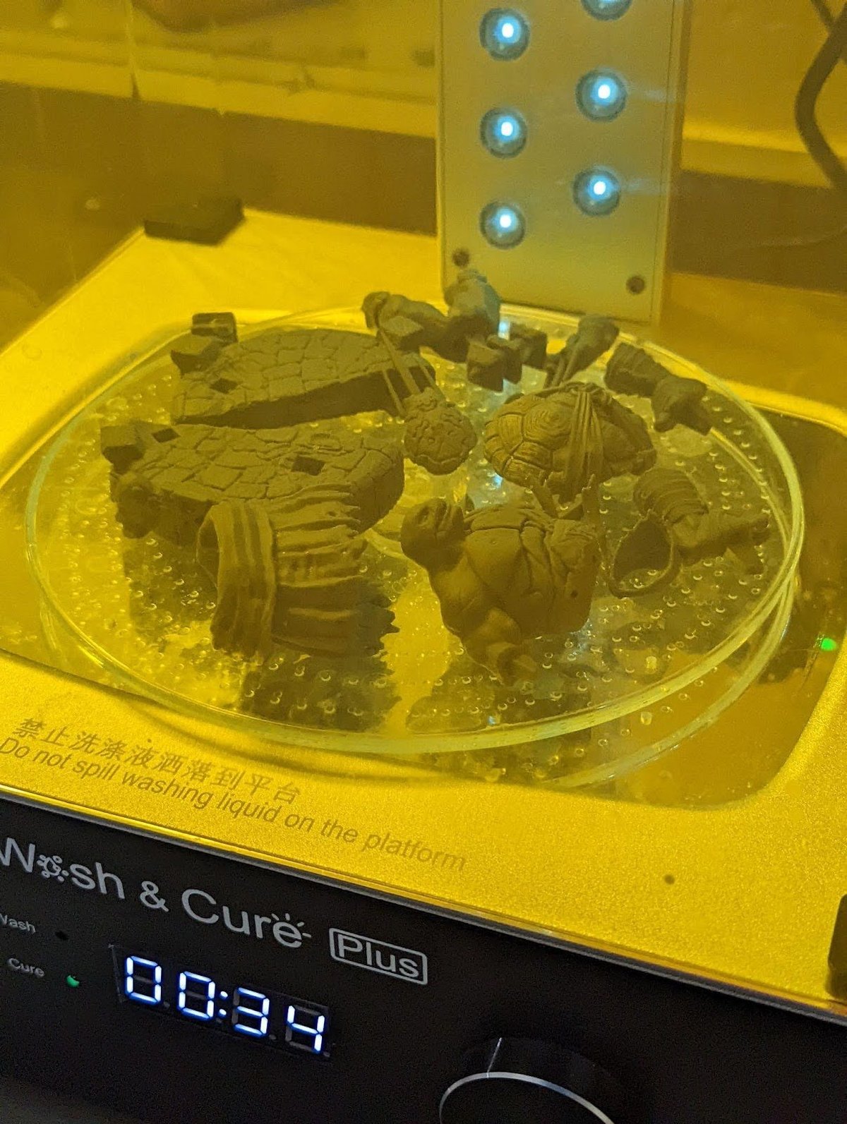
Final Cure
Do a quick 30 seconds then check for any dripping resin. Especially from hollowed models. Flip the models and do 3min, repeat till your resin is fully cured.
Can you over cure resin 3D prints?
No, but also yes.
Fast ABS like “hard” resins, the UV reaction will continue till there are no more binders to react to the UV light. At this point the resin is fully cured & more UV will have no effect.
Flexible, clear or Cast resins, you can over cure them. But in post curing, and when printing. Be careful using a calibration part that could lead to overcuring. These need to be cured in a way that preserves the color, flexibility or burn out. It’s best to follow the manufactures post cure processes.
Wear a mask and UV glasses when using a UV light. When using a cure station, leave the room. This will create toxic fumes.
If you don’t have a cure station I recommend the Beast UV Flashlight. Remember always wear UV glasses, or you can go blind, your choice.
Cleanup and Disposal
Trash
Make sure you cure all your supports, used paper, used gloves and any resin waste.
I throw them into the trash and use my UV flashlight to cure them all at the end of each print. You may also choose to throw everything into a small clear container and cure it using a flashlight or your cure station before you dispose.
Cleaning your FEP
See my video on how to properly clean your FEP below:
Do this after every print – unless you use the silicone spatula method to stir and check your FEP before every print. Most 3D printers have a tank clean option; see your manual to find this function.
Keep a stash of tall supports that you can use as handles to easily remove the cured resin from the tank clean process.
- Place one of the saved supports near the edge or corner. Lightly press the Raft of the support against your FEP.
- Run your Tank Clean Option normally for 10 seconds. In some printers it’s called exposure.
- Pull on the support towards the center of the VAT. This should peel the cured resin off of the FEP along with any trash from previous prints.
- Move the cured sheet of resin away from your printer and cure it the rest of the way before disposable.
Emptying and Removing The Vat
I highly recommend buying a large syringe to suck the resin out and run it through a paint filter back into your resin bottle. Find the link at the bottom.
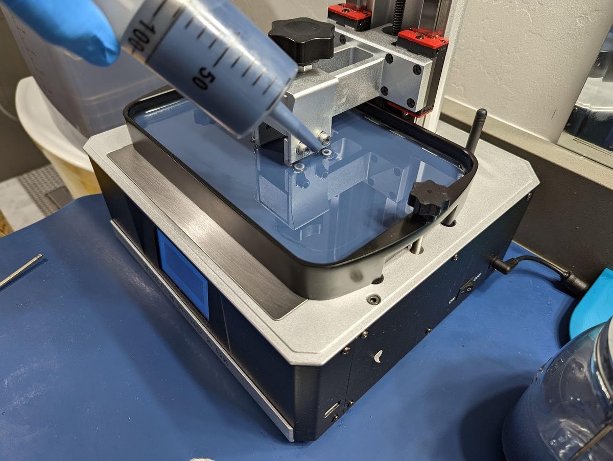
Once your VAT is mostly empty it’s much easier to pour the remainder into the filter by hand.
Every time you remove your VAT, you expose your LCD to dust, hair, falling objects like build plates and resin. This is just one of the reasons to level in the VAT.
- First remove your build plate, you DON’T want it to drip resin down on your exposed screen.
- Remove the VAT
- Remove the resin using IPA, even water washable.
- Dry it using clean paper towels.
- Buff streaks out using a lint free cloth.
- Blue painters tape to remove any dust and hair.
Clean your LCD
- Clean the LCD using IPA.
- Dry it using clean paper towels .
- Buff streaks out using a lint free cloth.
- Blue painters tape to remove any dust and hair.
- Reinstall the VAT as soon as you can to protect your LCD from getting damaged/dirty.
- Make sure the VAT is secured down fully.
- There is no need to re-level your 3D printer after this.
Troubleshooting Print Failures
Layer Lines

Layer lines can be very frustrating, potentially ruining a perfect print when in the wrong place. Here is a list of potential causes.
- Not enough supports to keep the object solid on all three axis.
- To fast lift speed
- Low temps
- Hollowing with no suction release.
- No rest time (Light off Delay)
- Temperature changes during the print
- Pausing the print
- Adding resin during a print.
- Power delivery issues during the print.
- A dirty printer causing the rails or screw to catch.
Volcanoes
If you ever see these large bumps on your 3D print it could mean a few things:
- Not enough supports and/or your support tips are oversized.
- The weight of your model is creating too much surface tension.
- Massive peel force, caused by large cross-sections.
- Resin flow causing cross-curing
As volcanoes can be caused by multiple things there can be different ways to resolve it:
- Add a LOT more supports with ~0.4 mm tips
- Reduce the weight by using hollowing
- Reduce the cross-section by hollowing or different orientations on the plate. But not forgetting the skyscraper method.
- If you have the skill, slice the model into smaller parts. This resolves issues 1-2. You can even place the supports in sections that will be internal, completely hiding support damage in the final product.
- If the model is too flat, the resin won’t drain between layers. The UV light will penetrate several layers and cure trapped resin around the supports.
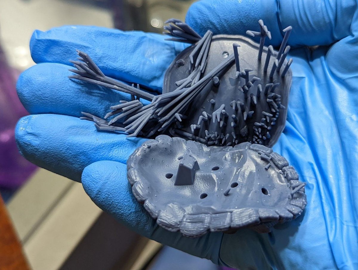
Just the Supports
Not enough support.
But why would I say this is most likely the cause? What do we know:
- The rafts are not lifted in any of the corners but are secure to the build plate, this means;
- Burn in layers are correct.
- The build plate is level.
- The supports are fully formed down to the tips, this means;
- It’s not an issue with under exposure. Please STOP adding UV exposure time to resolve an under supported model.
- The USB drive is in good condition.
- The models do not have bad geometry. This would cause some parts to fail and others to print.
- The pulling force (Bed raise speed) is probably not an issue.
- The supports are different showing multiple models of different heights and size, this means;
- It’s not an issue with room temperature changing, as this would cause failures at different places on different models.
- It’s not a suction issued caused by a larger model
- It’s not a weight issue caused by a large cross section.
After eliminating a lot of things, what’s left? Well, not enough support.
The fix: Increase support contact with the model.
- If you have Lychee Pro, see this video. If you don’t have Lychee Pro, keep reading.
- Add 4-times the supports, and yes I do mean 4-times at minimum.
- Make sure you’re using the correct support sizes.
- Medium support tip of 0.40 mm is the correct size to anchor any models of any size if you have enough.
- Light supports, like the ones you see in this example are ONLY used to keep small details.
- Do not attempt to use lightsupports in any quantity to keep a model to the plate.
Split-Rafts
- The quantity of burn in layers including transition layers are too many. Causing them to bleed into the support shafts. Or your raft is too thin. You want a 1.0 mm raft min.
- This can also cause an issue of hard-cured resin next to soft-cured resin, causing raft separation.
- Your burn-in layer UV exposure is fine but your supports shafts are undersized.
- Your lift speed is too fast.
- You have bad resin. Bad resin could mean, not mixed well, a bad batch or ECO resin.
- Energy supply inconsistent
- This kind of error could also be caused by an inconsistent energy supply from your network. Try moving your machine to another outlet which you know is not within the same electrical line.
Supports Not Printing or Stop Printing
Problem: Z-offset is off causing layer compression.
This means that the very first layer being printed is too close to the LCD and there is not enough room for all the layers to be correctly printed. This is mostly an issue when printing the raft due to the larger cross section and extra heat generated by curing the raft.
Why does it affect the supports?
I believe it’s because the FEP is pushed into the LCD with too much force causing very bad things to happen:
- The rest is pushed out of the way making for a bad cure.
- The FEP being pushed against the LCD will stick causing it not to release correctly creating a stuck layer that will cause a failure.
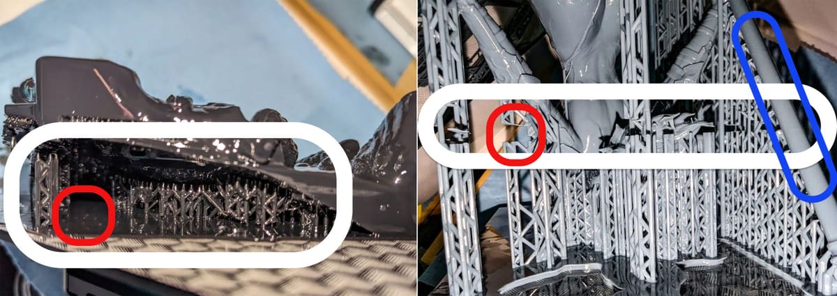
- Supports are more likely to have this issue due to their cradle nature when compared to a thicker object like a model. See the BLUE area.
- This will decrease the life of your FEP, SCREW and LCD due to the extra pressure.
Fix: See Build Plate Calibration in this guide for the instruction to set your Z-offset and check your level.
Nothing on the Build Plate
- Make sure that your resin is mixed well, including squeegee the FEP to pull in the layer that separates from the resin.
- Print above 20 ºC, preferred 25-30 ºC.
- Be sure your Build Plate is properly leveled, see Supports Not Printing or Stop Printing.
- A FEP free from excessive damage.
- A clean LCD free from any fibers or streaks.
- 4-6 burn in layers, 3-6 transition layers.
- Increase burn in time by + or – 4.0/s till the model sticks but is still easy to remove.
- What works for one size of object, may not work for another. Use the Small, Medium and Large method I talk about in this guide to calibrate for each.
- You need more Light off delay (Waite Before Print).
- Your Retract Speeds are too fast. Try to keep them under 100mm/m. If your printer supports TSMC, slow down to under 60mm/m for the final 1-2 mm.
Missing Prints on Half the Build Plate
Your build plate is not level.
Prints on one side of the build plate are successful. However, prints on, the opposing side are hanging off or failed completely. See Build Plate Calibration.
Cross Curing (Z-Blooming)
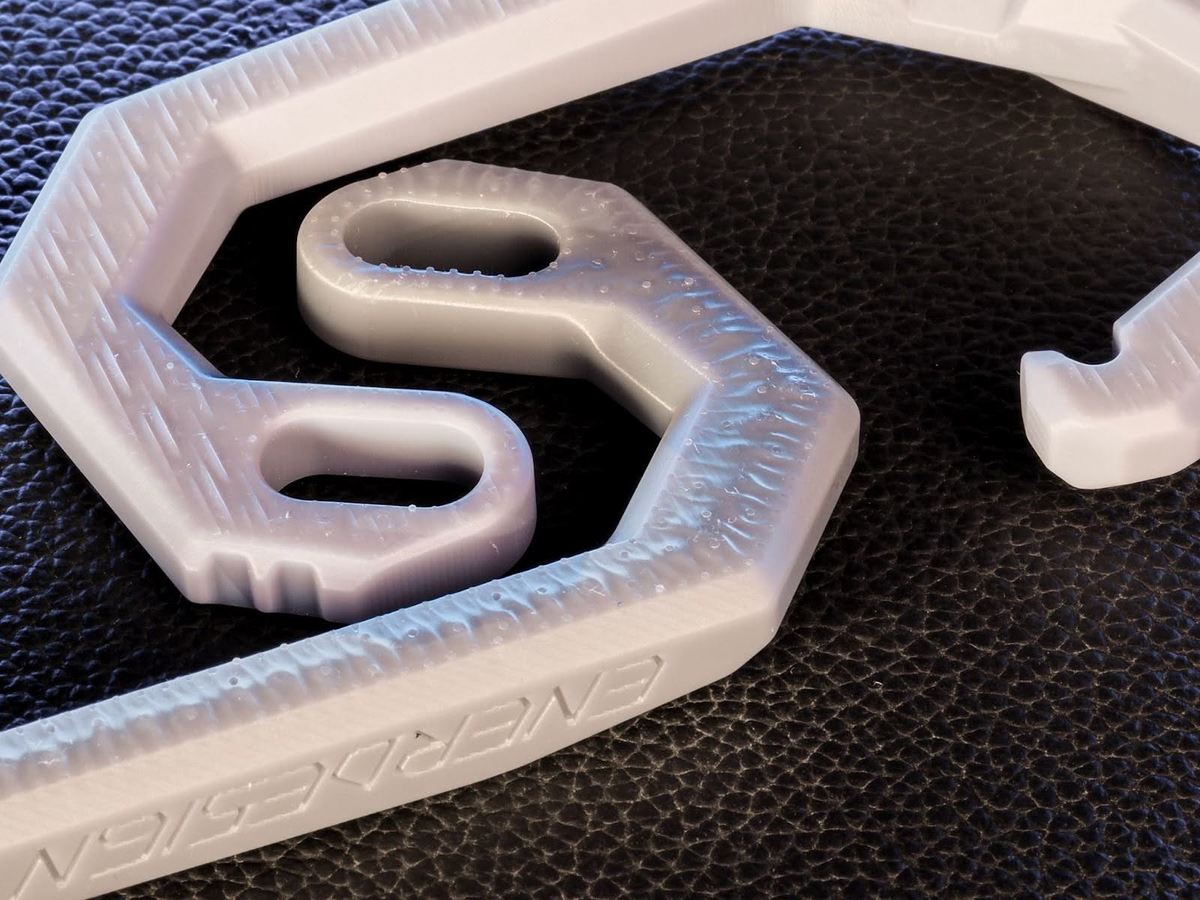
When more resin is cured than expected on X and Y, we call that blooming. On the Z or Height, we call that cross Cross Curing, Z-Blooming.
In the example of Cross Curing above, the bracket on the top was printed with a very accurate resin greatly reducing the pillowing effect found on the bottom bracket. You will even notice that the damage caused by supports is significantly reduced. Despite both prints using the same support settings and both resins perfectly calibrated for dimensional accuracy.
If you’re using a resin, like clear or flexible, that’s not as accurate what can you do?
- Make sure that the surfaces facing the build plate are not parallel to the build plate. The more angled they are the less opportunity for cross curing. However, don’t go crazy with this. Remember the three objectives listed on Model Orientation.
- Calibrating to Dimensional Accuracy.
- Printing thicker layers 50um
- Printing at medium temperatures, below 26 ºC but not colder than 20 ºC.
- Turning down the UV power of your printer to 65% if supported and then calibrating to Dimensional Accuracy for this application.
Multi Cure Calibration (M.C.C)
M.C.C is designed to help you get “close” to the target UV exposure time. (Only available on some 3D printers)Can also be used as a stand alone Calibration method.
Download here
For any Concepts3D Printer there is no need to download as this Calibration print is included on the printer.
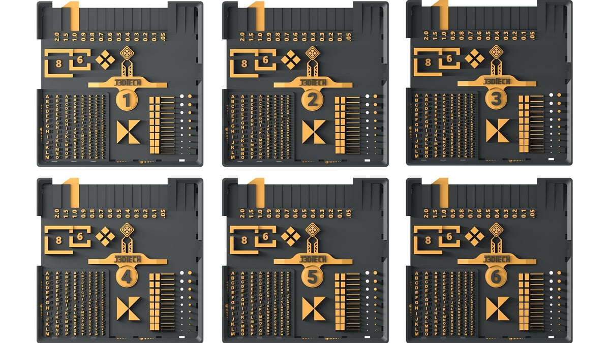
Eight unique 3D files are available. Each is labeled 1-8 in the center to be easily identified after being removed from the build plate.
How does it work?
Each plate is cured at a slightly different UV exposure time. Allowing you to test 4, 6 or 8 (Depending on your printer) UV exposure times in a 30 min or less print!
Should be followed up with Boxes of Calibration for the final and best calibration you can ever get!
How to read the Multi Cure Calibration print?
Pins and Holes
Goal: Get as many pins as you can to print, while also still being able to visibly see the smallest holes measuring only 0.2mm. Use the larger Pins and Holes to help guide you through the Calibration process.
Results: All pins should print, and the smallest hole should be visible.
Gaps and Walls

Not all resins will be able to 100% pass this test. On the right you’re trying to get thin sheets of resin to print and stay standing. On the right very thin gaps you’re trying to not allow to fill in with cured resin.
Goal: Achieve both standing walls and clear gaps as far down the test print as possible.
Result: Better results mean better resin/printer and calibration.
Right Side: Aim for thin, standing walls.
Left Side: Aim for clear, unfilled gaps.
Adjust: Tweak UV exposure time and wait time.
The Tablet
We all know what basic text should look like, hopefully? (This is a visual accuracy test.)
Goal: The raised and indented text should be legible.
Result: Better results mean better resin/printer and calibration.
Three Triangles or is it 6?

Very similar to the infinity symbol this are 3 points that almost touch (This is a visual accuracy test.)
Goal: Get all three points to just barely touch while not filling in the 3 empty triangles (Empty space).
Result: Better results mean better resin/printer and calibration.
Dimensional Accuracy Check

You can use Digital Calipers or even the Boxes from Boxes of Calibration to check Dimensional Accuracy.
Goal: Get each measurement to measure within 0.02mm for high accuracy resins 0.04mm for softer resins.
Result: A best way to objectively identify how much blooming your resin has on XY.
4mm: The 4 posts will measure 4mm on the outside. The space between the 4 posts is 1mm, this can be used as a Raft thickness check.
6mm: is 4mm on the inside, 6mm on the outside.
8mm: is 6mm on the inside, 8mm on the outside.
Using the Raft you may measure the distance between the test and the edges.
2mm: left of the 8mm to the edge of the raft.
18MM: The total length of the test.
24mm: From the 4 posts to the left of the raft.
Z offset and Level
Why not do more than one thing at a time?
While you’re calibrating your normal layers, you can also make sure that your printer is Level and that your Z offset is correct!
Goal – When printing only one: The 1.0mm check point should read between 0.7mm and 1.1mm. The closer to 1mm the better. Saying within 0.04mm is the goal.
Goal – When printing multiple for M.C.C: The difference between the thinnest raft and the thickest raft should be no greater than 0.04mm. All rafts should not measure under 0.7mm or over 1.1mm.
Result: In a perfect world all rafts would measure 1mm. This would mean a perfectly flat build plate, a perfectly level printer with a perfectly set Z offset. Because we don’t live in a perfect world.
Use Digital Calipers to measure either check point marked 1mm to check for Z-offset.
Additionally using the 0.05mm – 2.0mm check points you can find out how your printer progresses though the Z-offset issues over the first 2mm.
Due to the physical size of this calibration part, you will want to make sure that you’re using extra Light off Delay or Wait Before Print on the bottom layers. Or this will most likely measure 0.2 – 0.4mm too thick.
This can be used to troubleshoot prints failing to hold onto the build plate, or split rafts. To learn more watch this video!
Labels and Notes
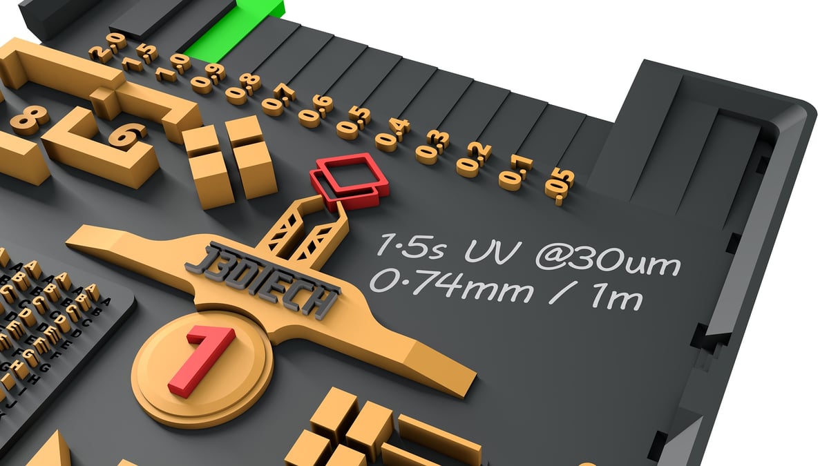
This spot is reserved for wiring down whatever you like.
In this example 32s for the bottom UV exposure time and 1.5s for normal UV exposure time.
The 1.0mm raft thickness check point measured 0.74mm.