Sheet Metal Design with Designcenter Solid Edge from Siemens: 5 Best Practices You Wish You Knew Earlier
Discover five essential practices that will help you achieve "first-pass-right" sheet metal designs, avoid costly rework, and streamline your fabrication process.
Getting sheet metal right starts before the laser fires or press brake starts. A single bend radius mismatch, a missing relief, or a K-factor set by gut feel rather than gauge table can turn a clean design into a costly rework loop. The designers who avoid that loop aren’t necessarily more experienced. They are, however, working within a system built to catch errors before they reach the shop floor.
We’ve been working for many years with Designcenter Solid Edge as our 3D CAD solution for designing HVAC systems for on-road and off-road vehicles. We especially appreciate its sheet metal capabilities, as they allow us to streamline complex geometries, reduce development time, and ensure a smooth transition from design to manufacturing.
– Jan Rennies, Project Engineer at SANZ Dreiha GmbH
Here are five practices that separate first-pass-right designs from the ones that come back from fabrication, and how Designcenter Solid Edge portfolio of product development tools for mechanical and electrical design can help you more easily achieve them.
1. Lock Your Parameters Before Geometry
If material thickness, bend radius, and bend allowance aren’t defined before geometry begins, nothing downstream is reliable. It’s a common shortcut: rough out the shape and “clean up the data later.” That shortcut quietly multiplies rework.
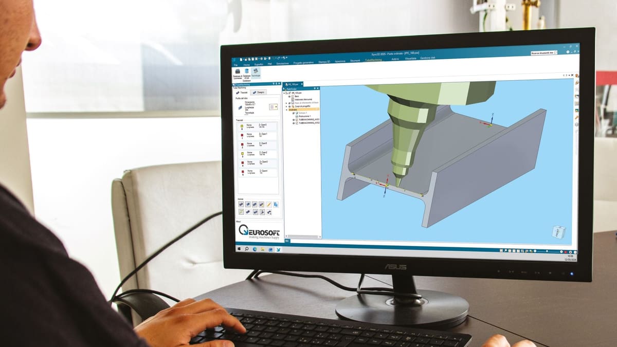
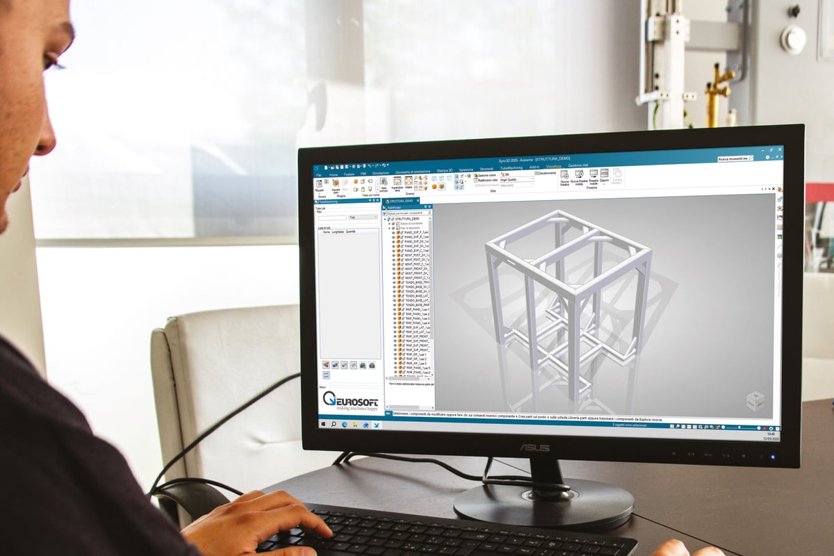
Eurosoft has built its software Sync3D on the proven mechanical CAD foundation of Designcenter Solid Edge OEM from Siemens. What truly sets it apart for us and our customers is the comprehensive sheet metal design environment, seamlessly integrated with core modeling and documentation capabilities. This enables our customers to deliver highly specialized solutions that streamline workflows and ensure precise, production-ready results.
– Gianluca Medini, Technical Director, Eurosoft spa
The fix is standardization, using, for example, Excel-based gauge tables that centralize bend data across your entire team. Designcenter Solid Edge enables this at the platform level by using shared parameters that enforce consistency across product families, so you are never manually guessing a K-factor mid-project. You’ll define it once, then apply it everywhere.
2. Use Features That Think Like a Fabricator
General solid modeling tools are geometry-blind when it comes to fabrication. An extruded cut doesn’t know it’s crossing a bend zone, just as a pushed surface doesn’t understand grain direction.
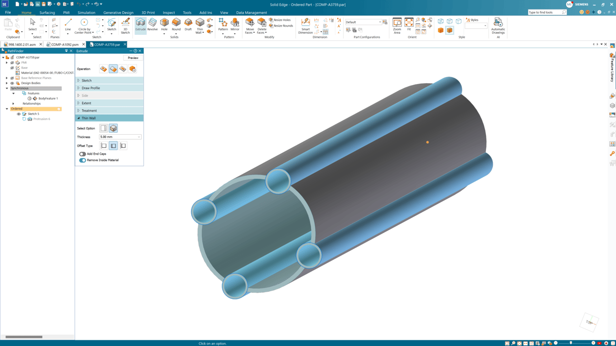
Dedicated sheet metal features, such as Contour Flange, Normal Cutout, and Lofted Flange, embed manufacturing intelligence directly into the model. When Designcenter Solid Edge generates a flat pattern from these features, it uses real bend calculations rather than geometric approximations. That distinction is the difference between a part that fits and one that ends up in the scrap bin.
3. Treat the Flat Pattern as a Real-Time Validation Tool
Most designers treat the flat pattern as a final export step. The smarter approach is to use it as continuous feedback throughout the design process. Folding and unfolding the model as you add features lets you verify bend reliefs and corner conditions in real time.
Solid Edge can cover all the different requirements of freeform surfaces for endless screws all the way to sheet metal unfolding, piping and cabling. It is ideally suited for plant construction.
– Florian Sondermeier, Team lead Design, HECHT Technologie GmbH
Designcenter Solid Edge maintains an associative link between the folded model and the flat pattern. A bad corner relief caught on the third bend is a 30-second fix. The same error caught during nesting halts production and requires a complete redesign, meaning the association is both a convenience and a cost-control mechanism.
4. Design for the Revision That’s Coming
Sheet metal parts are rarely static. Manufacturing provides tooling feedback, engineering revises flange lengths, and customers change requirements. Rigid feature trees turn those normal changes into hours of rebuild work.
Designcenter Solid Edge’s Synchronous Technology addresses this directly. It allows direct edits to faces, angles, and cutout positions without navigating feature history. For design-to-order environments where iterations are constant, like complex textile machinery with large-scale sheet metal assemblies, that flexibility means a 5 mm change remains a five-minute task.
5. Encode Manufacturing Constraints Into the Model
Drawing notes are the weakest link in fabrication communication. If an operator misses a note about minimum flange length or grain direction, the part is ruined. The stronger approach is to encode those constraints directly into the 3D geometry, where they cannot be overlooked.
For more than 25 years, we have relied on Solid Edge as our 3D CAD system for the design of specialized machines used in precision surface finishing and grinding. In particular, the Synchronous Technology for sheet metal design stands out as exceptionally powerful.
– Markus Müller, Senior Project Lead Design, Team Lead CAD/PLM, Supfina Grieshaber GmbH & Co. KG
This is Design for Manufacturability in its most practical form. Designcenter Solid Edge supports it through a combination of parametric controls and manufacturing-aware features that reflect real shop capabilities from the first sketch. The result is a first-time-right approach that reduces the back-and-forth between design and production that quietly destroys project schedules.
Such an approach isn’t achieved by luck. Instead, it relies on the right infrastructure. Designcenter Solid Edge gives you the automation, rule-driven edits, and clean flat pattern generation to build that infrastructure into every project. Ready to eliminate fabrication rework?
To discover what’s new in Designcenter Solid Edge Sheet Metal, please watch this Expert Community Talk, read this whitepaper, and participate in this upcoming webinar.