Stop Wasting Filament: Master 3D Print Infill Patterns for Stronger, Lighter Parts

Get infill density and pattern wrong and your print wastes filament, snaps, or takes forever to print. Read on to learn how to get it right.
Stop relying on your slicer’s default infill pattern. The secret to balancing print speed, overall part strength, and material usage is dialing in the best infill density and pattern for your project’s unique mechanical demands.
Unlike most traditional manufacturing techniques, 3D printing allows you to carefully control two of the most important features of a part: exterior walls (or perimeters) and infill. The walls, however thick, form the outermost regions of the part, while the infill is whatever exists within them. Walls offer limited control, but infill is far more dynamic, and plays a major role in a part’s strength, weight, structure, buoyancy, and more.
In 3D printing, these characteristics are governed by parameters set in your slicer program. The two most important of these parameters are infill density (0% to 100%) and infill pattern (usually a choice of more than 20 designs).
Unlike milling or injection molding, where you have the choice of solid or empty as your infill, 3D printing provides the freedom to create complex geometries inside the part that are nearly impossible or too expensive to make with traditional manufacturing. Sometimes the infill pattern can make the part even stronger than solid and, when it comes to flexible parts, like shoes, you can alter the flexibility of sections of the same part by adjusting the infill.
Let’s take a look at your options and how to apply them to your 3D printed parts.
What is Infill Density?
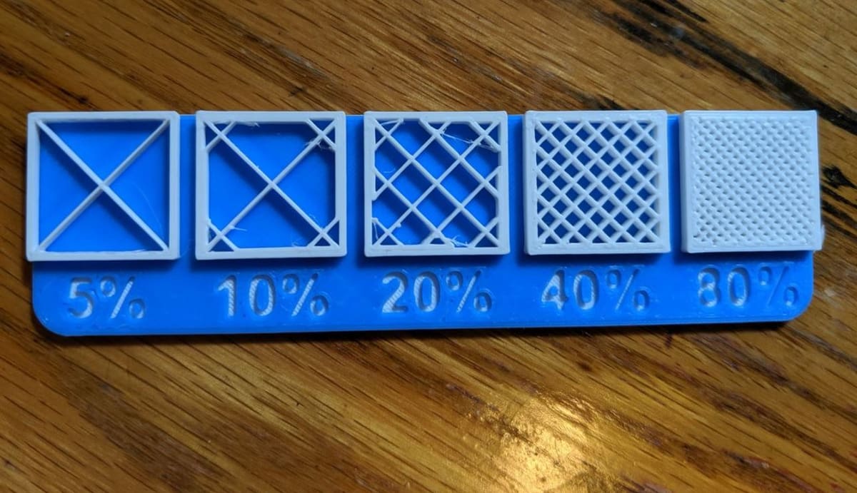
Infill density is the “fullness” of a part’s interior. Slicers define it as a percentage between 0 and 100, with 0% leaves a part hollow, 100% makes it completely solid. As you can imagine, this greatly impacts a part’s weight, but solid isn’t always strongest.
A part’s strength is a combination of its design, materials, layer height, and other factors, but infill plays a big part. We actually have an entire article dedicated to infill strength linked below:

Spoiler: In a nutshell, for maximum strength parts, you'll want a cubic, gyroid, or triangles infill at 15% - 25%.
Density also affects print time, material consumption, and even buoyancy.
Some slicers allow density to vary within a single part, known as “variable infill density,” where different zones can be reinforced only where needed, without adding weight everywhere. We’ll cover this variable infill approach later in this article.
What Percentage Should I Use?
Choosing an infill density comes down to what the part needs to do, but the percentage alone doesn’t determine strength. Material, print orientation, wall thickness, infill pattern, and the direction and type of load can all be just as important.
For ordinary models and lightly loaded parts, around 10%-25% infill is a useful starting point, keeping print time, weight, and filament consumption relatively low. Functional parts that need additional stiffness or strength may benefit from roughly 25%-50%, although adding more walls can often be a more efficient way to reinforce a part.
Densities above 50% are best reserved for parts with unusually high strength, stiffness, or compression requirements. A full 100% infill provides the most internal material, but it substantially increases print time and filament use and is rarely necessary. Rather than automatically making an entire part solid, it can be more efficient to reinforce highly loaded areas with additional walls or local infill modifiers.
Display models such as figurines can usually use relatively sparse infill, around 5%-15%. Completely hollow, 0% infill can work for suitable geometries, but top surfaces and shallow slopes may need internal support to print cleanly.
Lithophanes are a special case because the image area needs to transmit light consistently, so it is commonly printed nearly or completely solid; enough closely spaced walls can accomplish the same goal in some models. Threaded or fastened parts may also need extra material around holes and bosses, but that does not necessarily require 100% infill throughout the whole model.
With flexible filaments such as TPU, infill becomes another way to tune the feel of the finished part. Lower densities generally allow greater deformation, while increasing the infill density makes the part stiffer and more resistant to compression. Wall count, infill pattern, and the hardness of the TPU itself also have a major effect, so there is no single percentage that suits every flexible print.
Slicer Presets
Most modern slicers now offer built-in density presets that are tailored to different print needs. These presets help users quickly choose the right characteristics for a good print without manually needing to adjust each setting.
For example, in Bambu Studio the infill density’s percentage is set under “sparse infill density”. The software also holds some predefined print modes, such as “Standard”, “Strong”, and “Draft”, which often come paired with recommended infill patterns, which are ideal when slicing speed is a priority. These modes indirectly influence the density and print strength by changing various settings.
Meanwhile, UltiMaker Cura offers intent-based profiles, such as “Visual”, “Engineering”, or “Draft”, which automatically adjust the infill density and related parameters based on the intended function of the print, while withholding strength where it’s needed most, especially near the outer walls. However, it’s worth noting that the intent-based profiles are available only for UltiMaker S series printers.
20+ Infill Patterns: How to Choose
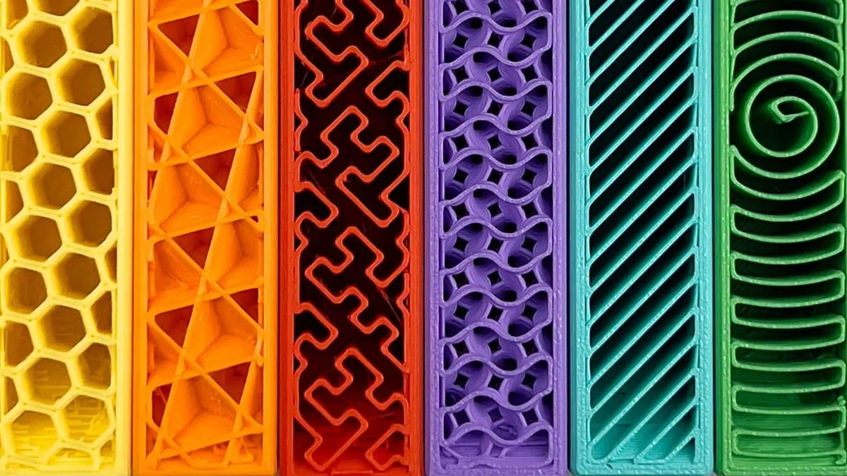
Infill pattern is the structure and shape of the material inside of a part. Ranging from simple lines to more complex geometric shapes, infill patterns affect a part’s strength, weight, print time, and even flexibility.
Like infill density, some patterns are better than others for certain functions. For example, the gyroid pattern connects walls in three dimensions, providing more overall strength. As a result, this pattern takes up more material in comparison to patterns such as lines. And then, across different slicer programs, there are many different infill patterns. For example, Cura (5.13) has a selection of 16 infill patterns, while PrusaSlicer (3.0) has 18 and Bambu Studio has 22.
So, Which Pattern Should I Choose?
To help you choose a pattern that best suits the needs of your part, here’s an overview of 15 common options, based on their comparative strength (and the number of planes of directed strength – 2D or 3D), material efficiency, print time, and common uses.
Infill Patterns for Figurine & Display Prints
Figurine and Display Prints
- Lines: The lines infill pattern contains lines printed in one direction (either along the X- or Y-axis) on every other layer. This infill pattern provides strength in only two dimensions and is good for quick prints but is among the weakest patterns. The lines pattern doesn’t use too much material and keeps weight pretty light. This pattern is best suited for early-stage prototypes or form-check prints, such as a quick phone stand or a draft version of a part. It’s fast to print, but lacks structural strength.
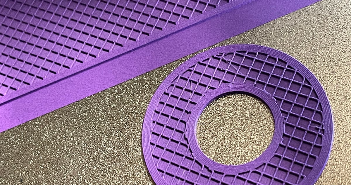
- Grid: The grid infill pattern is typically default. It is similar in look to lines, but instead of one-directional lines every other layer, it contains two-dimensional lines every layer, with twice as much space in between lines. The grid pattern consumes an average amount of material and takes a middling time to complete. This pattern is commonly used in parts such as mounts, be it for a wall or camera or any housing purpose, since this pattern provides two-dimensional strength and yet strong, making printing easier.
- Lightning: This pattern is designed to act as internal support by focusing material only where its structurally required – primarily beneath the top layers or overhangs. The resulting tree-like structure looks like lightning bolts, hence its name. The selective density approach significantly reduces print time and material usage, therefore making it well-suited for fast and economical prints. It’s ideal for prototypes, decorative models, or shell-only designs that don’t require high internal strength.
- Voronoi: This is a geometric structure that divides space into regions based on the proximity to a set of points, resulting in organic shapes that resemble natural formations like a honeycomb or a bone structure. Unlike other patterns, though, it’s not available directly in slicers but rather needs to be implemented in other programs; the method involves modifying the geometry to incorporate the pattern before slicing.
Infill Patterns for Standard Prints
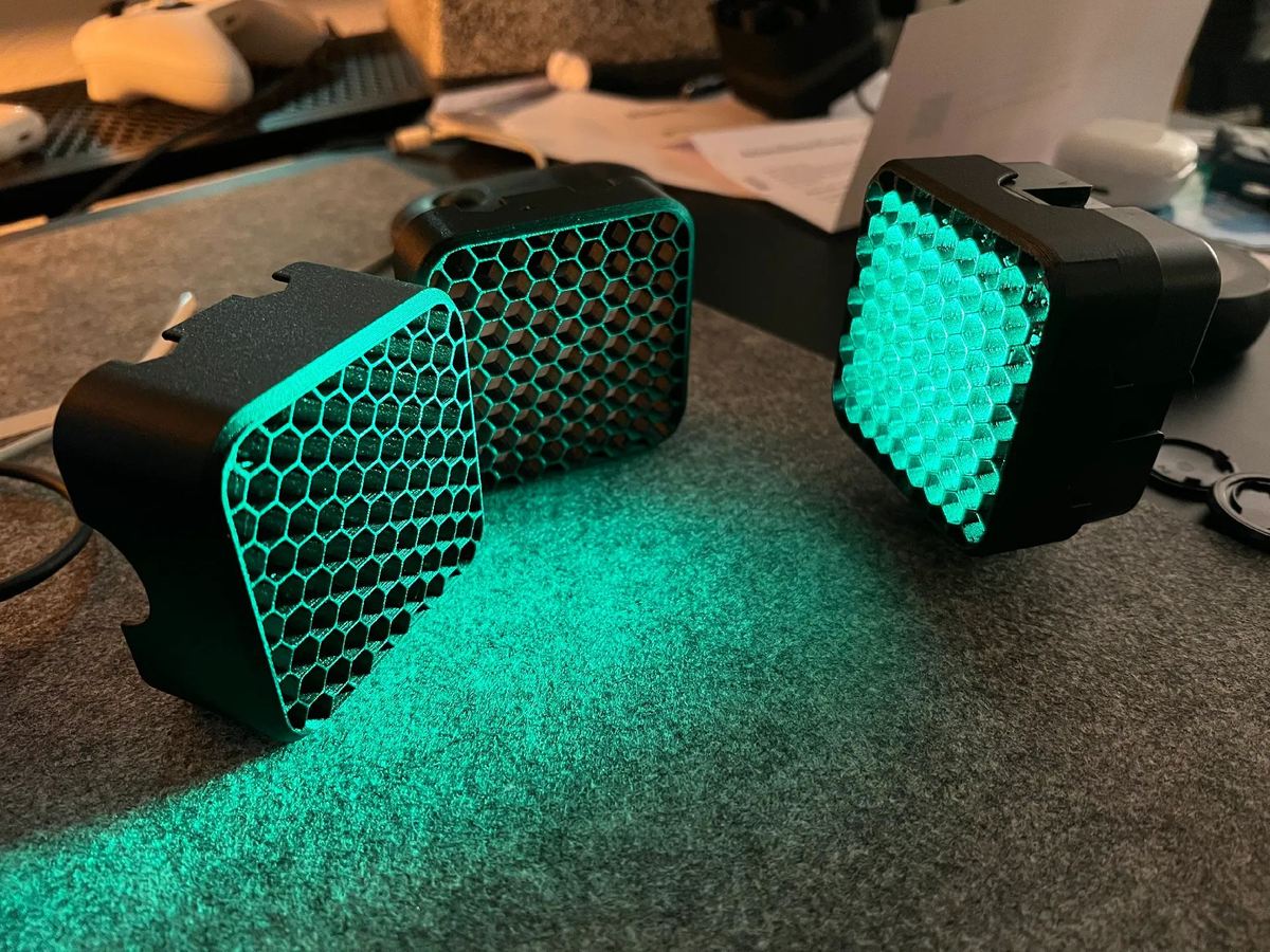
- Honeycomb: As the name implies, this pattern produces a honeycomb structure, making for an appealing visual. This infill pattern is well-suited for semi-fast prints that require moderate strength, and shouldn’t consume too much material. It is particularly useful for prints that need consistent rigidity without too much added mass. Some use cases can be for drone bodies, durable components for a skateboard, or structural panels that require critical strength. This is because the honeycomb’s hexagonal pattern distributes force evenly, which makes it great for such parts that maybe subjected to vibration or impact.
- Grid: Same as in the section above for less supported models, but if you boost the density it becomes a universal choice.
- Triangles: The triangles pattern looks like overlapping triangular lines, with lines going in three directions in the XY-plane. This infill pattern provides strength only in two dimensions but still works for prints that need to be strong. This type of pattern is great for flat objects requiring rigidity, such as flat covers used for enclosures, especially non-load-bearing mechanical covers.
Infill Patterns for Functional Prints
- Tri-hexagon: The tri-hexagon infill pattern contains an assortment of lines going in three directions in the XY-plane, creating hexagonal patterns with triangles in-between. This infill pattern provides strength in two dimensions and is pretty decent for strong prints, and it can also yield a cool aesthetic look. It can be suitable for speaker grills, decorative tech covers, and so on.
- Cubic: This pattern produces stacked cubes, but because they’re tilted by 45 degrees around both the X- and Y-axes, they appear more like triangles in any one moment. The pattern provides excellent strength in three dimensions but takes a little more material and time than others. It’s ideal for mechanical parts that take stress from multiple directions, such as drone arms, structural joints, and connectors.
- Cubic Subdivision: Essentially the smart version of the cubic pattern, this one uses less material to help increase print speed without sacrificing strength. The pattern is composed of cubes of different sizes, with the larger cubes placed at the center of the part; it increases density near the perimeters while reducing the infill in the center. Keep in mind that cubic subdivision can have longer slicing times. This pattern is referred to as Adaptive Cubic in slicers like Bambu Studio and PrusaSlicer. The option is ideal for printing enclosures and large parts with thick walls, such as tool case lids.
- Quarter Cubic: This pattern features tetrahedrons and truncated tetrahedrons, resulting in strong infill that can distribute heavy loads well. It’s suited for thin functional parts such as robotic shells or component spacers that require strength. However, the surface quality may be affected by the bridging distance, and it’s worth keeping in mind that this pattern uses less material than full cubic infill.
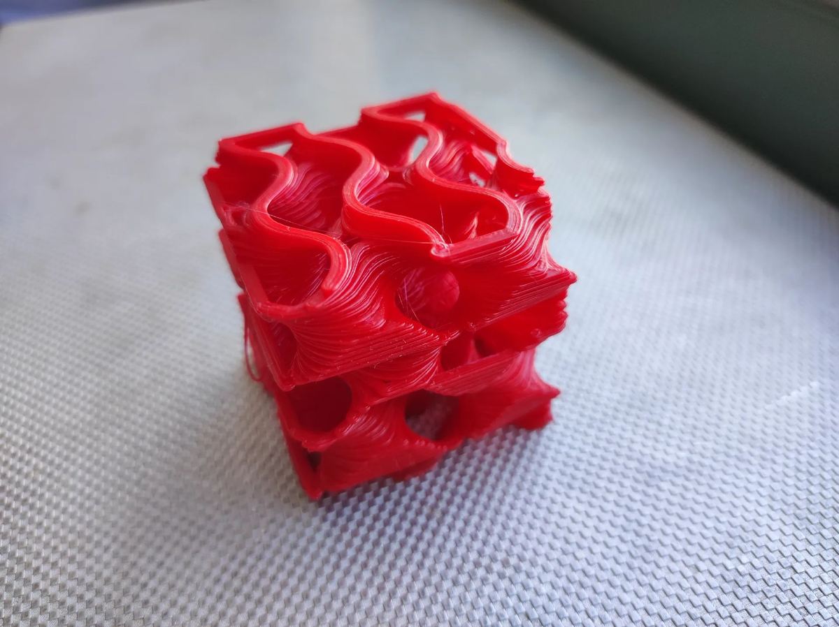
- Gyroid: The gyroid infill pattern may perhaps look the coolest, but it’s also arguably one of the strongest infill patterns. The gyroid pattern connects walls in three dimensions, providing more overall strength, but as a result, it takes up more material in comparison to other patterns. It includes concaving irregular curvatures that eventually cross paths. It’s meant to strike an optimal balance between strength, material, and print time. The uses cases are plenty, such as prosthetic limbs, bike handle grips, and wind-tunnel structures.
- Octet: The octet infill pattern is similar to the cubic pattern, but instead of increasing sloped triangles, the pattern materializes as squares. This infill pattern is a three-dimensional pattern that not only looks really great but is also useful for parts that require strength. This pattern is preferred for engineering-grade components such as motor mounts, 3D printer parts, and jigs and fixtures for your workshop.
Infill Patterns for Flexible Prints
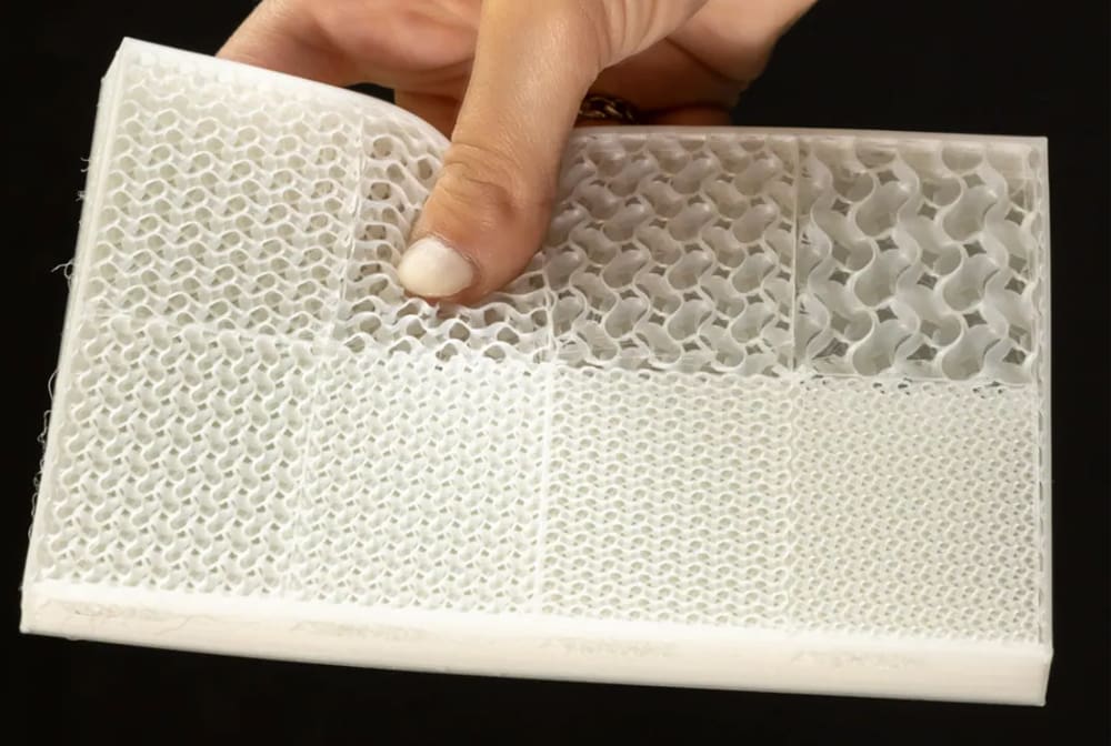
- Concentric: The concentric infill pattern is an internal structure composed of concentric lines that match a part’s outline (i.e. its perimeters). This design is quick to print, and consumes significantly less material than most patterns. This pattern follows the contour of the model and typically used in TPU gaskets, shock absorbers, or even wearable bands.
- Cross: Ideal for flexible filaments, this infill pattern creates crosses within the part. Since there are no long, straight lines, it allows for bending and twisting. However, the strength along the Z-axis makes it less flexible vertically. The cross pattern is commonly used for ergonomic grips, flexible mobile phone cases, or certain fidget devices like squeezable buttons.
- Cross 3D: To get rid of the vertical strength in the cross pattern, opt for cross 3D. The 3D version is soft and flexible in all directions. The only downside is that it has longer slicing times. As with cross, retraction isn’t required, which prevents the oozing of flexible filaments. For visually striking but strong prints, Cross 3D pattern is a good choice. This can be used in artistic light lamps or decorative vases where the print’s form matters more than the function itself.
Infill Troubleshooting
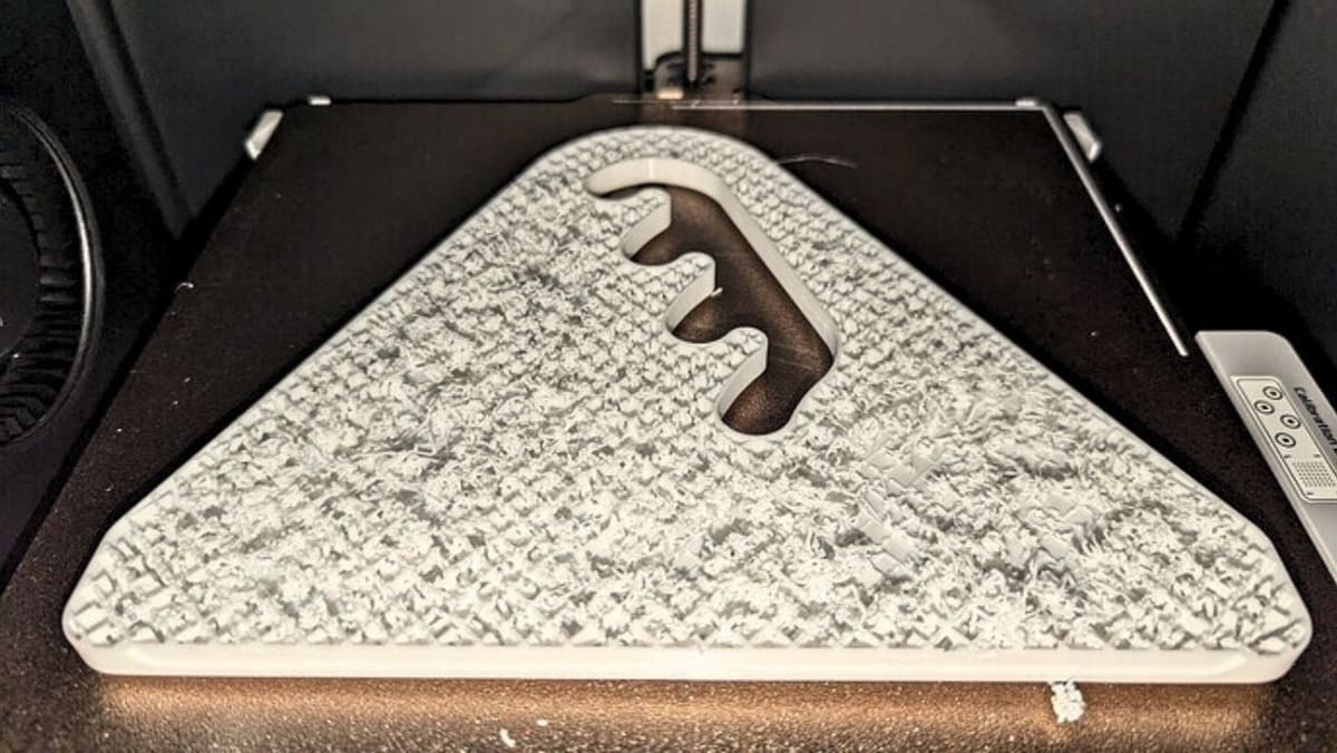
While infill patterns and densities are useful to add strength, they can sometime cause trouble if not set up properly. Let’s look at some common problems and how to fix them:
- Sparse infill collapse: If the infill density is too low, the 3D printed structure might not properly support the top layers, which might lead to uneven surfaces, sagging, or pillowing. The best way to fix this issue is to set the infill density and, if the part is too uneven once printed, increase the percentage for a new print. Inserting solid layers at regular interval can also help, such as can be found on PrusaSlicer under “Solid Infill every X layers”.
- Under-extrusion within infill: This occurs when there are weak, broken, or incomplete infill lines, resulting from under-extrusion. This might happen because slicers print the infill faster and with thinner extrusion lines compared to the perimeters. The first solution is to reduce the infill print speeds to no more than 80 mm/s; as a general rule, reducing it by 15-20% compared to perimeter speeds should work. Alternatively, increasing the infill extrusion width about 120% wider than the nozzle diameter can help get better coverage. It might also be useful to check the PTFE tubes for clogging.
- Gaps between the infill and walls: When the infill doesn’t bond properly with the perimeters due to slicer settings that prevent or limit overlap, the part is internally weaker. A solution is to increase the wall/infill overlap setting on the slicer from, in the case of Bambu Studio, the 15% default to around 20%; it can also be measured to around 0.2 mm. Keep in mind that increasing it too much can lead to visual defects. Reducing infill speed slightly can also help for a better fusion.
- Inappropriate infill pattern: Using a fast but weak pattern, such as lines or lightning, for load-bearing components can lead to failure of the structure, even if the quality of the print is up to par. Sometimes, these issues can be fixed by just choosing the appropriate infill pattern, like cubic or gyroid for strength-based parts; some slicers offer specific settings, such as PrusaSlicer’s “Infill Density Gradient”, for a denser infill near the external walls, which improves the strength without hindering print time.
- Misaligned infill: There are times when the infill doesn’t line up layer by layer or it looks like it’s drifting across the print. This can occur due to hardware issues such as loose belts, pulley issues, or even slicer settings that push the printer’s speed limit. Fixes for this are straightforward because the issue is identified in the hardware and must be rectified there by ensuring that the belts are properly tightened. Slicers like Cura have an acceleration control setting, which shouldn’t be too high, for example beyond 1,000 mm/s2, otherwise the jerk to the printer can destabilize and misalign the infill.
It’s important to fine-tune these infill settings on the slicer and regularly check the hardware of the printer. This improves the quality of the print and extends the functional lifespan of the part.
Variable Infill Settings
Besides pattern and density, there are two other noteworthy infill settings that are worth knowing. While they might not be the first you’ll be looking into in your 3D printing journey, they can come in handy depending on the specifics of the model and its use case.
Variable Settings
Infill doesn’t have to remain uniform throughout a model. Several slicers allow settings such as infill density and wall count to be changed over selected regions, letting you put additional material where it’s useful without increasing the density of the entire print.
Bambu Studio offers two useful ways to do this. A Height Range Modifier can override settings such as sparse infill density over a selected vertical range of the model. For example, you could use 10% infill through the lower portion of a print and increase it to 50% above a chosen height.
For more localized reinforcement, Bambu Studio also allows modifier volumes to be added to a model. Shapes such as cubes can be positioned over a mounting point, screw boss, or other selected area, and settings including sparse infill density and wall count can then be changed only where the modifier intersects the model. This makes it possible to reinforce a relatively small stress zone without adding the same amount of material everywhere else.
Bambu Studio also includes Adaptive Cubic infill, which automatically varies the size of its cubic structure, producing denser infill closer to the model’s geometry and sparser infill farther inside. Support Cubic follows a related principle but is primarily intended to provide increasingly dense support beneath internal top surfaces. These patterns can reduce material use, but they aren’t substitutes for deliberately positioned modifiers when a particular area needs mechanical reinforcement.
PrusaSlicer offers similar control through Height Range Modifiers for changes over particular Z intervals and Modifier Meshes for localized changes, such as adding denser infill or extra perimeters around a highly loaded area.
PrusaSlicer’s Adaptive Cubic infill offers another automatic approach. Its cells become denser near the model’s surfaces and larger toward the center, reducing material use while maintaining support for upper layers. It should not, however, be considered a substitute for deliberately placed reinforcement.
In Cura, modifier meshes can also apply different settings to selected regions. One way to create them is to add a support blocker and change its Per Model Settings to modify settings where it overlaps the model. This can be used to change properties such as local infill density.
Cura also offers Gradual Infill, which reduces infill density in steps as the distance below a top surface increases. This can save material and print time while retaining denser support immediately underneath top layers. The solid top skin itself is still controlled by Cura’s top-layer settings.
Infill Layer Thickness & Angle
Some slicers can print infill at a different layer thickness from the model’s walls. Increasing the infill layer thickness can allow several infill layers to be combined and printed less frequently, reducing print time. Keeping it equal to the normal layer height produces infill on every layer. The effect on mechanical performance depends on the material, pattern, geometry, and loading, so changing this setting shouldn’t be treated as a universal way to increase strength.
Infill orientation can also affect mechanical properties. Alternating directions such as +45° and −45° are commonly used to provide relatively balanced behavior in the XY plane, and can perform well under complex or changing loads. They aren’t universally the strongest choice, however. If the main load direction is known, orienting extrusion paths more closely with that load can produce greater strength in that direction. Part orientation and perimeter layout should therefore be considered alongside the infill angle when designing functional prints.
Artistic Infill
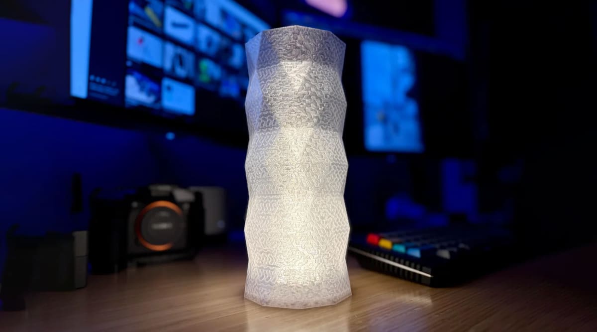
Infill can also become part of a print’s appearance rather than remaining hidden inside it. Patterns such as gyroid, triangles, honeycomb, or other geometric structures can produce decorative lattices for jewelry, ornaments, and display pieces.
Setting the number of top or bottom solid layers to zero can expose the infill on those faces, while reducing the wall or perimeter count can reveal it around the sides. Not every pattern remains self-supporting when its surrounding shell is removed, so checking the slicer’s preview before printing is particularly important.
A smaller nozzle can reproduce finer lattice details when the design requires them, but there is no single nozzle size or filament color that works best for infill art. Pattern, density, orientation, material color and translucency, and the surrounding shell can all be adjusted to produce different visual effects.
License: The text of "Stop Wasting Filament: Master 3D Print Infill Patterns for Stronger, Lighter Parts" by All3DP is licensed under a Creative Commons Attribution 4.0 International License.