
Reverse Engineering Parts With 3D Scanners & Software
Learn how to reverse-engineer physical parts into digital design models with the top software options for your 3D scan data.
Re-creating a part or product when there’s no schematic drawing or digital design file used to be a daunting task. Before 3D scanning technology was widely available, reverse engineering was done by hand by taking precise measurements of an object to produce a drawing.
That’s all changed now with affordable 3D scanning technology, easier-to-use software, and 3D printers to quickly produce models, prototypes, and, in many cases, the final parts.

What is Reverse Engineering?
On a broad level, reverse engineering is the act of dismantling an object to see how it works. On a practical level, reverse engineering is measuring a physical object and then reconstructing it as a digital 3D model, which can then be 3D printed or manufactured another way.
In this article, we’ll go over the step-by-step process of going from a physical part and ending up with a digital model, demonstrating the key steps and top tool options along the way.
But first, let’s look at what reverse engineering is used for today.
Applications of Reverse Engineering
Recreating spare parts and tools that are no longer manufactured is the obvious use of reverse engineering, but there’s so much more.
Improve Legacy Parts & Products
Many companies today still use decades-old molds to fabricate parts where the original designs and design decisions are lost to time. With digital models, you can improve on legacy parts, make them stronger or lighter weight. Perhaps the original design was developed before today’s sophisticated simulation and generative engineering software that can virtually test for stress response and use AI to offer improvements.
Aftermarket Customization
Especially in the automotive industry, offering products and accessories that perfectly fit your new car is big business. For this, manufacturers need exact measurements and 3D scanning is the fastest way. You may not always manufacture these models, but 3D printing prototypes for fit and assembly testing is common.
Digitize Hand-Crafted Prototypes
Artists, designers, and car makers still model concepts in clay, but once the style is approved it’s time to put these products into production, starting with the digital model. Once scanned and digitized, these models can still be changed and put through stress simulations.

Preserving Antiquities
3D scanners have become standard equipment at the world’s top museums in an effort to preserve cultural heritage. Vast digital libraries house masterworks of art and artifacts, some of which are displayed virtually online to broad audiences, while others are carefully reproduced for display, which allows the original to be safely stored.
Jewelry & Art Reproduction
Reproducing family heirloom jewelry or sentimental objects is vastly more accessible today. Scan originals and scale to the desired size or scan to archive in the event of fire or loss.
Product Investigation
Companies often reverse engineer a competitor’s product to uncover how it was made, find its strengths and weaknesses, and learn from its innovations. Recreating the product, of course, comes with copyright, trademark, and intellectual property limits. Reverse engineering is also used to investigate how an event, such as a car crash, may have happened by 3D scanning the crashed car and comparing the digital model to that of a new car.
3 Main Steps in Reverse Engineering
The process of reverse engineering follows a standard workflow that can vary slightly depending on the specific tools used and the desired outcome. Generally, the process is as follows:
- Data acquisition: There are various ways to collect dimensional data. The most common method today is through 3D scanning, which we’ll cover in detail next.
- Data processing: The data obtained from the 3D scanner is processed into a digital model. The raw 3D model usually requires some work to correct and refine certain regions that might not have been adequately captured during the scan.
- Model Building: The exact actions taken here are determined by the desired outcome of reverse engineering. If the goal is only reproduction, then the part can be ready for manufacturing. If fixes and additions are required, the digital model is manipulated in computer-aided design software.

Data Acquisition via 3D Scanning
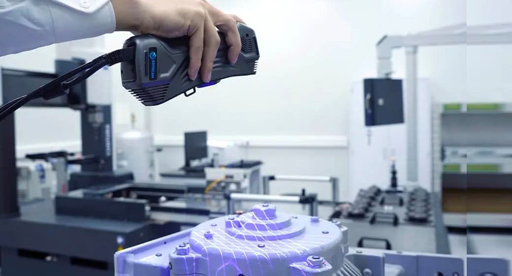
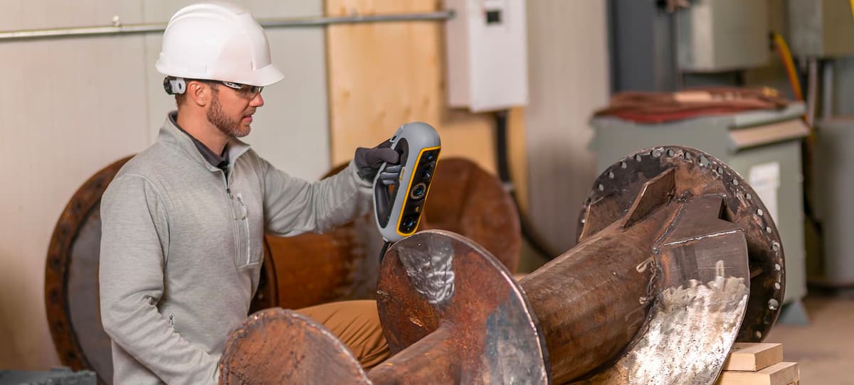
Different types of 3D scanning technologies make use of different methods for capturing data. They vary greatly in size and price, from hand-held devices to stationary bulkier systems. Each technology has its pros and cons and should be selected according to the size and type of object being scanned.
Reverse engineering is typically accomplished with optical-based 3D scanning using either structured light or laser beams. These scanners use triangulation with light and sensors to gather the reflection angle of the laser light. With the knowledge of the distance of the scanner from the object, the scanning hardware can map the object’s surface and record points to form a 3D scan. 3D scanning can capture the precise location of millions of points on the part per second, resulting in a massive amount of data.
These optical-based 3D scanners are famously accurate; the resolution ranges in the tens of micrometers. On the flip side, their range can be limited to only a few meters.
For detailed information in the best 3D scanners on the market, be sure to check out our round-up of products and related technology in the guide linked below.

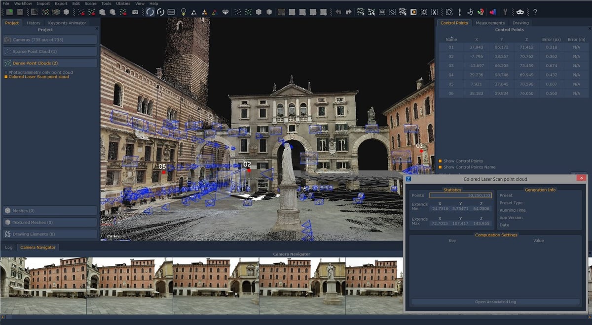
Photogrammetry is another 3D scanning technique where photos from different angles are stitched together to form a three-dimensional object. This technique relies heavily on software, which does all the hard work of processing hundreds of photographs to generate a 3D model. Photogrammetry has become more popular as smartphones have become more powerful since both photographing and processing can be performed right in your hands.
Although this newly accessible technology is great for producing digital color 3D models for viewing online, such as product images, the quality of data you’ll get from a smartphone app isn’t robust enough for true reverse engineering because the amount of data is too small or you’ll need to do substantially more work in your CAD program. If you’re keen to try smartphone scanning and low-cost photogrammetry, check out this guide linked below.

Data Processing for Reverse Engineering
Now that you’ve selected the best scanner for your application and budget and scanned your object, what’s next?
Unfortunately, 3D scanners collect data points about a physical object; they don’t create a digital model that you’d be able to directly fabricate. It’s a common misconception that optical 3D scanners output digital models. There’s another software step between scan data and the manufacturable model.
In fact, popular CAD programs, such as Autodesk’s Fusion 360 or Dassault Systèmes’ Solidworks, can’t read the raw data directly from a 3D scanner – it has to be converted into a model these CAD systems recognize and can process. (Sure, Solidworks has a feature called ScanTo3D, but it’s limited to working with low-resolution 3D scan data and is not applicable to reverse engineering.) Let’s explain.
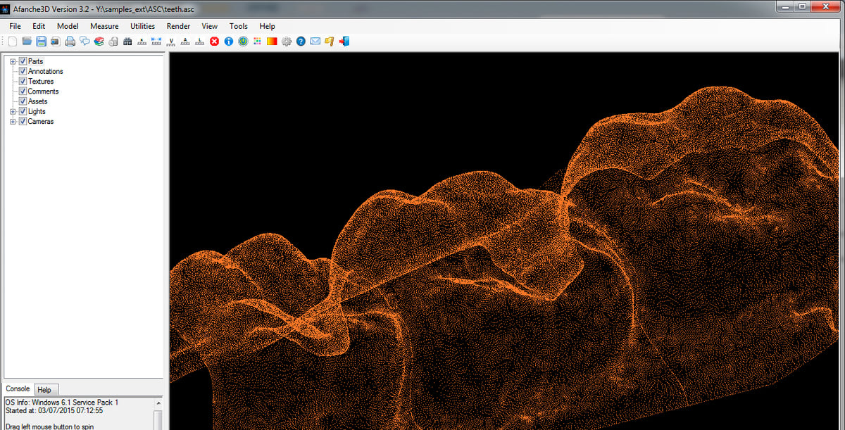
The more points in your “point cloud,” as raw scan data is called, the more accurate your model will be. (See the dental scan point cloud pictured below.) Accurate scan data saves a lot of time in the CAD step. Low-resolution data can give you a general outline to trace, but you’re basically recreating the part. On the other hand, you may not need all of those points for your application.
According to Mike Spray, owner of Laser Abilities, an equipment sales and 3D scanning service provider in Portage, Mich., “There’s always options for reducing the size of the point cloud by reducing the spacing between the points in the scanner’s software.”
The software that comes with your scanner is the first place to start editing the data, he says. Once you pare down your point cloud, the scanner software can then translate the point cloud to a model — or a 3D mesh as it’s called, which is made up of thousands to millions of tiny triangles or other polygons.
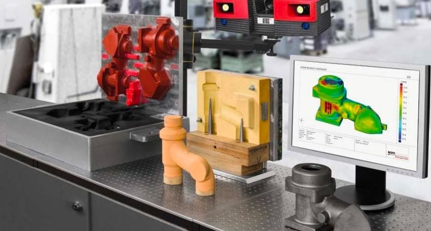
The software uses algorithms to “interpret” the point data and, in many cases, fill in the blanks from where the scanner didn’t capture enough data about the object, such as when a surface was too shiny and interfered with the scanner light. This is the point is where software vendors boast about the power of their property algorithms and other “smart” features designed to fix any anomalies in the point cloud data. Take a look at the image below of scan data versus the “cleaned up” model processed with the Artec Studio software from 3D scanner maker Artec 3D.

Some 3D scanner makers, such as Artec, Evixscan, Faro, and Zeiss, have developed sophisticated software companions to their hardware that, while not completely replacing CAD software, so a long way towards translating scan data to a CAD model. Other scanner makers, such as Evatronix, leave the interpreting step to third-party programs like the popular Geomagic. We cover all of these in the sections below.
“From the full or ‘water-tight’ mesh is where you can then go in different directions,” says Spray. “The mesh can be exported directly to your 3D printer’s slicer software as an STL file. The mesh doesn’t have an actual thickness, but that can be applied in the slicer.” From here, you simply hit print.
This mesh-to-slicer process is used to make an exact physical copy of an object. You might use this method to print products that are used as models to test fit into another assembly, for example.
For most reverse engineering, however, there are more steps because the product scanned may need to be repaired or modified for manufacturing. Depending on how well the data acquisition went or how precise your scanner is, the model might require corrections, cleanups, refinement, or even some minor surface tweaking.
To create a piece of tooling, for example, alterations are made to account for the manufacturing method. “If you’re casting or injection molding, you need to add draft so that the part can release,” says Spray. “So you might want to add three or five degrees of draft to the part. Your scan data would not have that in it.” Likewise, some metal 3D printing methods require you to account for shrinkage in the manufacturing process.
Matching your reverse engineering objective to your software isn’t always easy. Often, the software that comes with your 3D scanner will do. Sometimes you’ll save a lot of time in your CAD program by using a program between your scanner and your CAD program that is specially created to edit scan data. We cover the top options and their prices below.
3D Scanner Software
When selecting a 3D scanner, also consider the two kinds of software that are available with it. In fact, owning a good 3D scanner is only half the battle. The ability to properly capture a physical object is equally affected by the software used to process the scan as you’re scanning. This is the first type of scanning software you’ll use, and it’s a feature of your scanner not an option. It essentially determines how easy your scanning process will be. Not only does it guide you through the scanning workflow, but it also provides real-time feedback on your movement of the device, letting you know if you need to rescan a section.
The second, and often optional software, is for after you’ve collected the scan data. It aids in converting it to a digital model. This type is often offered as an optional subscription by your scanner maker.
If your preferred workflow is to have the scanner software do most of the scan data manipulation with a host of easy-to-use automated tools, there are options from most of the major scanner brands, including Artec, Faro, Shining3D, Evatronix, and Zeiss.
Although 3D scanner software isn’t intended to replace a full CAD system, it can accomplish most of the work toward converting scan data to a manufacturable model. For example, they can not only generate data to fix gaps or holes based on adjacent areas, but these programs can impose basic geometric features (planes, columns, cylinders, spheres) to your mesh model.
If you’d prefer that your scanner simply output robust data that you’ll edit in your favorite CAD or scan-to-CAD software, most scanners will do that, and then you can use stand-alone products such as Geomagic, Autodesk Meshmixer, the free version of GOM Inspect, and plug-ins to Solidworks or other CAD programs.
Artec Studio
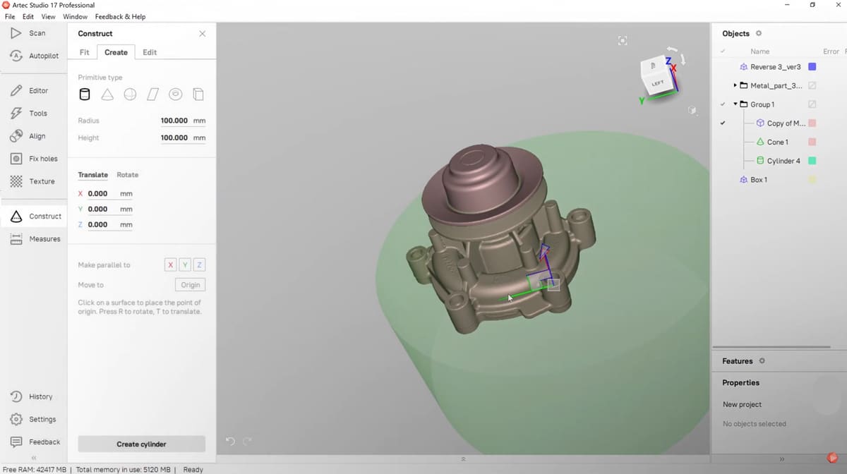
Artec Studio is the software from 3D scanner maker Artec3D and is definitely an example of software that brings more functionality to the table. Over the years Artec Studio, currently on version 17 with 18 due out this year, has advanced its automatic processing of scan data and its AI features that make scan-to-mesh almost a point-and-shot operation.
The autopilot function selects the most effective 3D algorithms for the data at hand after you input a few basic perimeters. The AI function captures hard-to-reach areas, sharp edges, and small and thin elements in high resolution.
Artec Studio comes with some handy and unique features, such as the Radar mode that lets you know if you’re holding the scanner at an optimal distance, and the Smart Base Removal that recognizes the base your object is standing on and automatically eliminates it from the scan, even if that surface is curved.
For pros, Artec Studio offers a wide range of tools for you to process your 3D scans manually, giving you full control over your data. There are hole-filling tools, texture applications, and tools that enable you to inspect, compare, and measure your models. You can speed up your workflow by performing key reverse engineering operations right in Artec Studio, such as applying primitives (basic shapes) to save key geometrical data, and fitting surface patches onto your mesh model to create a CAD surface body in one click.
- Platform: Windows
- Subscription Cost: €800 /year
Zeiss GOM Inspect (free)
GOM Inspect software is a versatile program capable of quickly processing simple or complex 3D scan data tasks from capturing the original part with a Zeiss to GOM scanner, processing the mesh, and repairing for CAD import.
There’s a Pro version of GOM Inspect and a handy free version. With the free version, you can import data from almost any brand of 3D scanner (and CT scanners) to be processed. GOM Inspect Pro is also scanner agnostic.
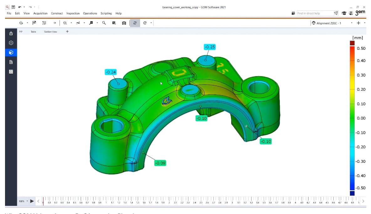
As you can guess by the name, Inspect is designed for inspection tasks, in other words evaluating a part to ensure that it was manufactured exactly to specification. Just like reverse engineering, this entails scanning the part, converting the point cloud data to a mesh and comparing the model to the original CAD model. The Pro version includes a host of inspection-specific tasks, such as traceable evaluation and reporting, that you wouldn’t necessarily need with reverse engineering, but the free version is nicely robust.
GOM Inspect free includes all of the mesh processing in the Pro version, including tools for smoothing and refining polygon meshes, filling holes, and extracting curves, all with a live preview of each step before executing. Neutral CAD formats such as IGES, JT Open, and STEP can be imported into free GOM Inspect.
You can also apply free-form surfaces and primitives to your meshes, such as lines, planes, circles, or cylinders. Even the free version enables you to carry out geometric dimensioning and tolerancing (GD&T) analysis focusing on the functional aspect of a part. The software conforms to ASME and ISO standards and allows extensive GD&T analysis, including planarity, parallelism and cylindricity, two-point distances, maximum material conditions, as well as position tolerance in local and global coordinate systems.
- Platform: Windows
- Subscription Cost: Free
Geomagic Design X
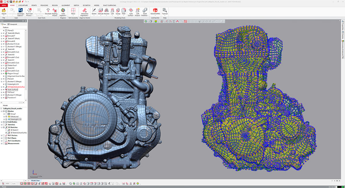
Geomagic Design X from Oqton creates CAD models from 3D scan data, and claims to be the fastest at processing large scan data sets with millions than any other reverse-engineering software.
Geomagic Design X is marketed as a reverse engineering platform. It supports all major 3D scanners, imports all raw data capture, and works with all file formats. In fact, it’s one of the only direct 3D scan data to CAD software programs available, enabling you to bypass even the software that comes with your 3D scanner, which is handy if you have a variety of scanners at your business and want one platform to run them all.
The post-processing is also done entirely within the same environment, with tools created for this sole purpose, but if you’d rather work within your Solidworks platform, you can use the special Geomagic for Solidworks version that plugs directly into your Solidworks environment, giving you advanced capabilities to make tools, point clouds, and polygons more usable in your design process. Geomagic Design X also connects directly to other CAD software, including Siemens NX, Solid Edge, Autodesk Inventor, and PTC Creo, and with 3D scanner software, such as Artec Studio.
Using the LiveTransfer technology, Design X transfers complete models, including feature trees, so you can quickly create solid and surface models from 3D scans.
One of the most powerful capabilities of Geomagic, lies in the mesh-to-solid conversion. It uses a combination of automatic and guided tools to streamline this time-consuming process as much as possible. This also includes many CAD features that will shorten your workflow significantly, such as mesh repair tools for hole filling, smoothing, optimizing, re-wrapping, and polishing.
With all of these features, it’s no wonder Geomagic Design X is one of the pricier options. A lower-cost version of Geomagic with fewer features is available as a Solidworks plug-in.
- Platform: Windows 7+ (64-bit Edition)
- Price: $20,000
FARO RevEng
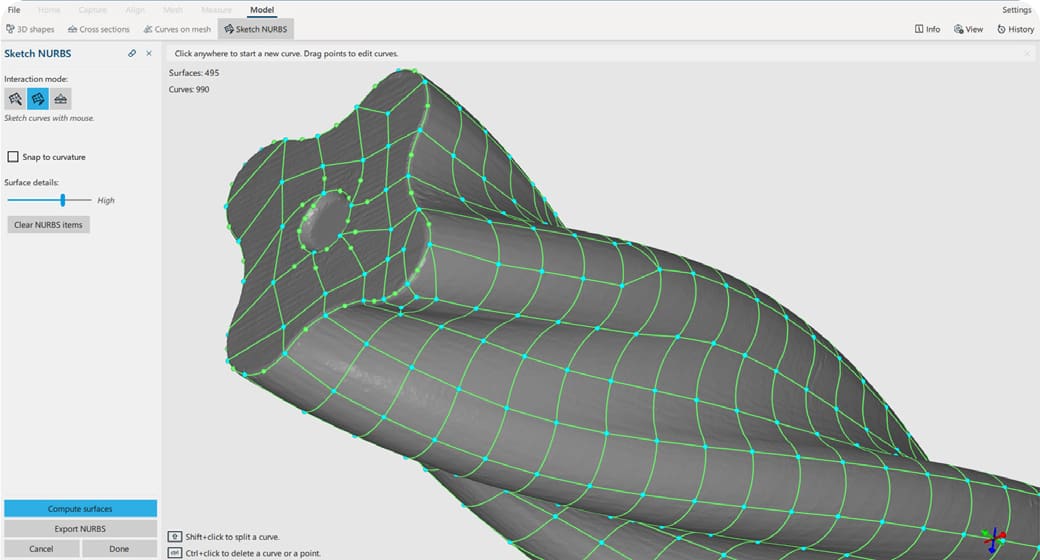
3D scanner maker FARO offers its RevEng Software platform designed for reverse-engineering applications. It helps you create and edit high-quality meshes and CAD surfaces from 3D point clouds then use these mesh models for further design or direct 3D printing.
The editing tools include mesh fixing, advanced repair and adjustment tools, and enhanced smoothing. You can also export watertight meshes and create CAD-ready surfaces including automatic NURBS (non-uniform rational B-spline). Data ranging from high-resolution color point clouds to simple mesh files can be transformed into detailed meshes, providing more insight into the design, composition and visual differentiation between materials and textures. RevEng’s user interface visually displays all the tools within a single screen. This facilitates the easy manipulation and customization of a 3D object to meet specific design requirements, improving workflow productivity to provide users with a competitive advantage.
- Platform: Windows 10 64-bit
- Price: unknown
Polyga XTract3D (for Solidworks)
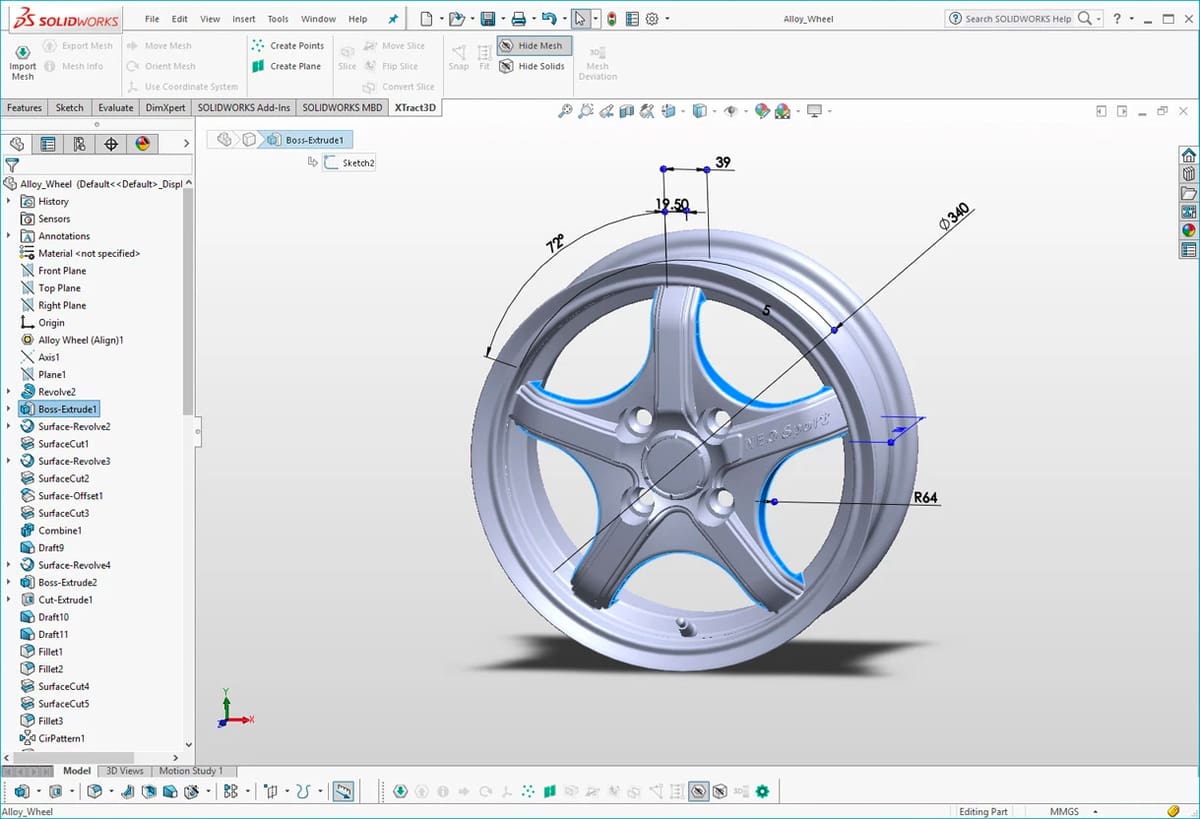
Already have SolidWorks, there’s an add-on called XTract3D from 3D scanner maker Polyga that’s designed specifically for reverse engineering applications and aims to facilitate the conversion from mesh to solid CAD models.
With XTract3D, you can either import the mesh file or even the point cloud data from your scan directly into SolidWorks. The wide array of tools allows for the proper tracing of even the most complex and organic shapes. XTract3D focuses on providing a basic yet powerful set of tools to manually extract features, sketch, and create CAD data using the 3D scan data as a template for design.
Once that’s completed, the model is ready to be worked on in one of the most professionally-used CAD programs out there.
- Platform: Windows 10 (requires a SolidWorks subscription)
- Cost: $1,000 for a lifetime subscription
Mesh2Surface (for Solidworks / Rhinoceros)
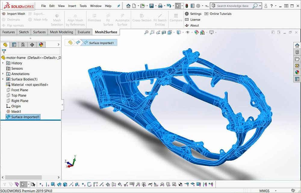
As you know by now, your scanner exports a 3D model mesh, but a mesh isn’t exactly smooth so you need to convert the mesh polygons to a surface. Ideally, you’d want a minimum number of polygons to get a smooth surface. Software like the aptly named Mesh2Surface can interpret your mesh and extract the smooth surfaces that you can then refine and manipulate in your CAD software.
Mesh2Surface is a plug-in for CAD program Solidworks or Rhinoceros. It provides the core features and functions required to create CAD data from meshed scan data from right inside your existing CAD software.
To start, you can use any 3D scanner which can generate good-quality STL meshes and import them with the plug-in. The makers of Mesh2Surface say they want to keep the plug-in simple and low cost so you won’t find all the bells and whistles of more robust solutions.
If you’re not using Solidworks or Rhino, you can use the Mesh2Surface stand-alone solution called Quicksurface. Its a cost-effective tool ($4,000) for CAD creation from 3D scan data for the majority of standard needs. There’s also an option to use it with Autodesk Inventor.
- Platform: Windows
- Cost: $3,000 Mesh2Surface (Solidworks)
- Cost: $1,300 Mesh2Surface (Rhino)
Autodesk Meshmixer (free)
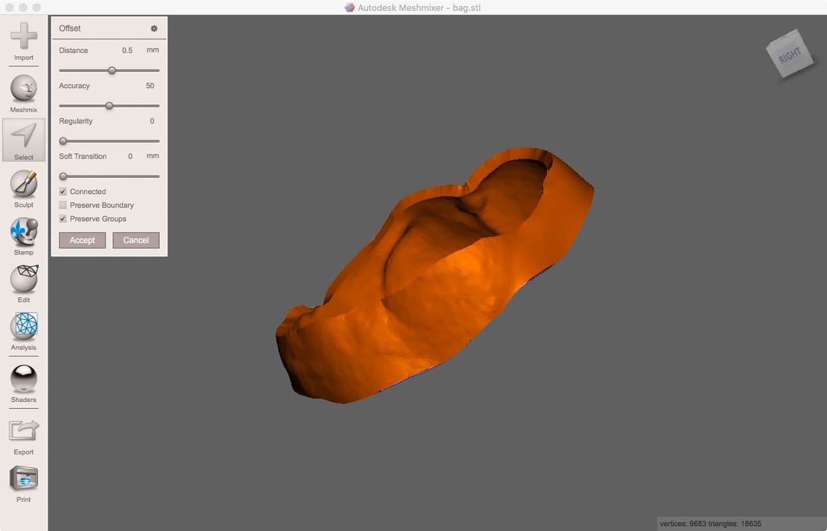
Autodesk Meshmixer is a tool for editing and measuring 3D scan mesh data. Since late 2021, it’s no longer supported or developed by Autodesk since the company moved several of its features to inside its other CAD software, but it still has a loyal following and it’s completely free. It has a great selection of tools that allow you to not only manipulate a model but also design it from the ground up.
Meshmixer is user-friendly and quite easy to navigate, with plenty of tutorials available online. The automated analysis and correction features come in handy for 3D scanning, and the program even provides some 3D printing model preparation, like custom supports.

- Platforms: Windows, MacOS
- Cost: Free
Model Building via 3D Printing
You now have your final model ready for manufacturing. 3D printing is the fastest and often cheapest way. You can simply upload your digital model to 3D printing service providers, like Craftcloud, select your material, and receive your print in a matter of days, sometimes faster.
If you’re keen to 3D print your model yourself, there are several different kinds of 3D printing technologies, countless materials, and thousands of printers to select from. Here at All3DP, we have thousands of guides on these topics and more.
License: The text of "Reverse Engineering Parts With 3D Scanners & Software" by All3DP Pro is licensed under a Creative Commons Attribution 4.0 International License.