The OBJ File Format – Simply Explained

The OBJ file format and 3D printing go hand in hand. Find out all you need about the OBJ file format for CAD and 3D printing.
OBJ is one of the more important file formats in 3D printing and 3D graphics applications. It’s the preferred format for multicolor 3D printing and is widely used as a neutral interchange format for non-animated 3D models.
In this article, we discuss the OBJ file format in detail and will go over how the format is different from other formats that are frequently used in 3D printing and graphics applications. For the hardcore readers, we’ll cover the full specifications so that you can read, understand, and tweak the files manually.
We’ll also go through the different features offered by the OBJ file format and provide tips on how you can use these features to improve your 3D models. For 3D printing hobbyists, we’ll answer some commonly asked questions on using the OBJ file format in 3D printing applications.
Let’s get to it.
What Is It?
Very simply, the OBJ file format stores information about 3D models. It was created by Wavefront Technologies for its Advanced Visualizer application to store geometric objects composed of lines, polygons, and freeform curves and surfaces. As such, OBJs can encode the surface geometry of a 3D model but can also store color and texture information. However, the format stores no scene information (such as light position) or animations.
An OBJ file is usually generated by computer aided design (CAD) software as an end product of the 3D modeling process. The file extension corresponding to the OBJ file format is “.obj”.
The file format is open source and neutral. It’s often used for sharing 3D models in graphics applications because it enjoys comprehensive import and export support from almost all CAD software. In recent years, it’s also become popular as a file format for multicolor 3D printing, since the otherwise standard 3D printing format, STL, doesn’t contain color and texture information.
Formats Compared
As mentioned, there’s a distinction to be made between 3D printing applications and graphics applications.
3D Printing
The most dominant file format in the world of 3D printing is STL. However, STL is an old file format that, though very popular, hasn’t kept up with the times.
3D printing has seen multicolor printing become more prevalent in recent years, which STL doesn’t support. The increasing accuracy of printers has also posed additional challenges for the STL format. For example, it can’t handle high resolutions very well, since a higher resolution design in the format comes with a significantly increased file size.
On the other hand, OBJs can approximate surface geometry as precisely as required without blowing up the file size. This is possible using Bezier curves and a method called NURBS, which we’ll get to later in this article. Furthermore, the OBJ file format has native support for multiple colors and textures within the same model.
So, the OBJ file format has a substantial advantage over STL if you need precise, multicolor models. As time goes on, it’s pretty likely to become increasingly popular because of this.
Despite that, the OBJ file format isn’t as universal as the STL format. Almost all 3D printers support STL, but the same can’t be said for OBJ – though it also enjoys reasonable adoption and support. Therefore, the STL format is still preferable if you’re 3D printing a monocolor model with a standard printer.
Both OBJ and STL formats have a very mature ecosystem with a large, invested user base and plenty of third-party tooling. There are other 3D printing file format contenders, like VRML, AMF, and 3MF, but they don’t have comparable support and, at this point, aren’t serious alternatives to the STL and the OBJ file formats.

3D Graphics Applications
The most commonly used file formats in 3D graphics applications are OBJ, FBX, and COLLADA.
Differences Between OBJ, FBX, & Collada
The most crucial difference between the OBJ file format and the others is the support for scene information (such as light sources) and animations. OBJ doesn’t support scene information or animations, while FBX and COLLADA do. Therefore, if you need animations for your game or movie, you’re better off using the FBX and COLLADA formats.
Advantages of OBJ
The OBJ file format is a simple and open format with wide export and import support among CAD software. This means if you share your 3D model as an OBJ file, it’s highly likely that other CAD software will interpret it correctly and consistently. The same can’t be said of the FBX or the COLLADA formats. The COLLADA format is also open source but is quite complicated, leading various CAD software to interpret it differently, leading to inconsistencies.
The FBX format is a closed and proprietary format that offers a software development kit (SDK) for converting existing formats into FBX (Export). However, it’s not so easy to go the other way – converting an FBX file into another format (Import). Developers of non-Autodesk CAD software typically have to hack their way into implementing a plausible FBX import, leading to inconsistencies.
Aside from broad compatibility, OBJ files are much more lightweight than FBX or COLLADA files of the same 3D model. This is due to the comparative simplicity of the OBJ file format and its native binary encoding.
If you don’t need the entire scene or animations and care about support and consistent interpretation between CAD software, OBJ is the right file format. In almost all other cases, FBX is the optimal format for 3D graphics applications.
FBX is the most progressive format, offering plenty of cutting-edge features with regular updates and improvements. The OBJ file format comes second in features, while the COLLADA format is considered slow to adapt.
Features
Having gone, in general terms, over how an OBJ file differs from other formats, let’s take a closer look at its features.
Geometry
The primary purpose of the OBJ file format is to encode the surface geometry of a 3D object, and it’s quite versatile in this respect. It allows several choices for encoding surface geometry: Tessellation with polygonal Faces, freeform curves, and freeform surfaces. We’re going to explore the advantages and disadvantages of each of these before moving on to the specification of the file itself.
Tessellation with Polygonal Faces
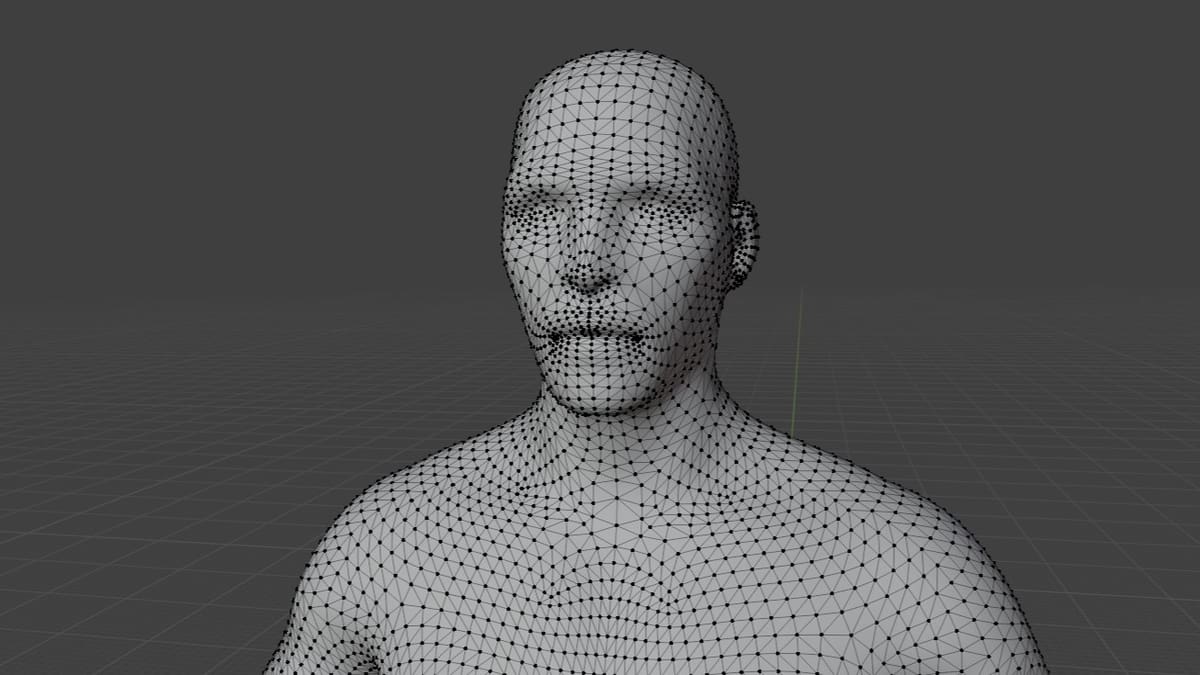
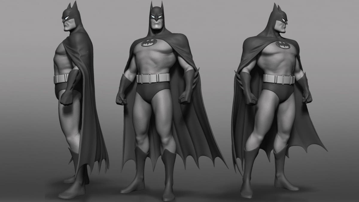
In its simplest form, the OBJ file format allows the user to tessellate (tile) the surface of the 3D model with simple geometric shapes like triangles, quadrilaterals, or more complex polygons. The vertices of the polygons and the normal to each polygon are then stored in a file to encode the surface geometry of the model. To illustrate this, above is an image showing how a 3D model of a male base mesh can be tessellated with tiny triangles.
Tessellations with polygonal faces have advantages and disadvantages. Polygons are simple geometric shapes; this method is the simplest way to describe surface geometry. However, approximating a curved surface with polygons introduces coarseness and geometric deviation from the model.
In the case of 3D printing, models will print with the same coarseness as specified by the file. Of course, by making the triangles smaller and smaller, the approximation can be made better and better, resulting in good-quality prints. However, as you decrease the triangle size, the number of triangles needed to cover the surface increases. This can lead to gigantic file sizes, which 3D printing slicers struggle to handle. Sharing or uploading huge files like that is also a real pain.
It’s therefore vital to find the right balance between file size and print quality. But reducing the size of your model’s triangles to the absolute extreme doesn’t make sense. At some point, you’ll get diminishing returns as the limiting factor will be both your printer’s and your eye’s resolution.
Freeform Curves
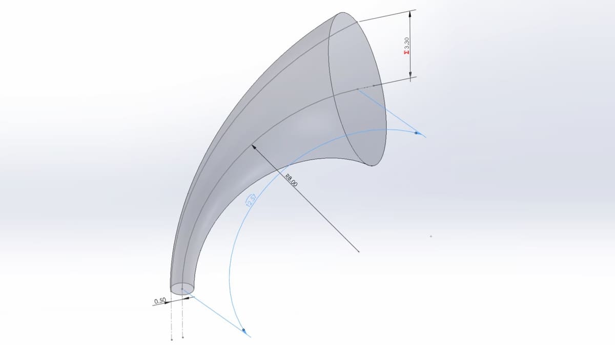
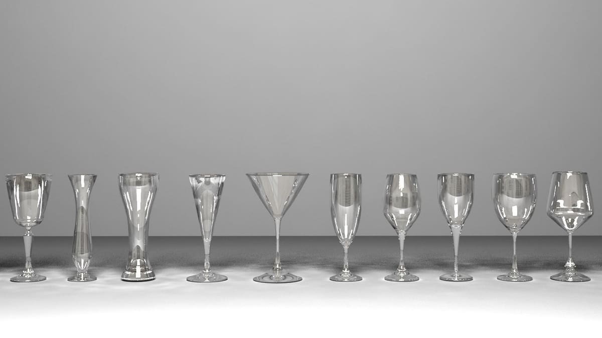
The OBJ file format also allows for specifying the surface geometry of a model using freeform curves. The basic idea is that the user defines a collection of freeform curves (cardinal Splines, Bezier curves, etc.) that run along the surface of the model. The surface is then approximated from this collection of curves. Above is an example illustrating a freeform curve on the surface of a 3D model.
As you can see, freeform curves are definitely more complicated than polygonal faces. But by sacrificing simplicity, we also gain a lot. Since freeform curves can describe curved lines exactly using a few mathematical parameters, they require fewer data to describe the same surface when compared to an approximate method like polygonal tessellations. Therefore, we can create a high-quality encoding of any 3D model using freeform curves without blowing up the file size.
Freeform Surfaces
With the OBJ file format, you can also specify the surface geometry by tiling the surface with freeform surface patches instead of simple polygons. This kind of surface patch is handy for describing surfaces that aren’t like planes, spheres, cylinders, or cones – surfaces that don’t have a rigid radial dimension. Examples of such surfaces include a car body, an airplane wing, or a boat hull.
The most common freeform surface is called NURBS (Non-Uniform Rational B Spline), and the OBJ file format supports it.
The advantages of freeform surfaces are somewhat similar to those of freeform curves – they’re more precise and lead to smaller file sizes at higher precision. In fact, one could argue that freeform surfaces are more precise than freeform curves, since they encode the surface exactly, as opposed to approximating the surface using curves. This is why freeform curves are often used in industries that demand absolute precision, such as aerospace, automotive design, and engineering.
Color & Texture

In many applications, the appearance of 3D models is of great importance. A racing video game with dull, colorless cars wouldn’t be much fun. They need to look like the real deal – and the same goes for just about everything you can see in a game that might add some sparkle. The color and shine of a car, a passersby’s shoes, and even ice cream are examples of appearance-related properties. In simple terms, appearance describes surface properties such as material type, texture, color, and more, which decide how a model looks when rendered.
Though the OBJ file format won’t let you store color and texture information itself, it makes up for this by allowing the storage of this information in a companion file format called Material Template Library (MTL). It’s possible to render a multicolor textured model by using these two files together.
MTL files contain ASCII text that defines the light-reflecting properties of a surface according to the Phong reflection model. One can define material properties like ambient color, diffuse color, specular color, transparency, and more. We’ll discuss the MTL file specifications in more detail in the next section.
In addition to supporting these material properties, the MTL format also supports texture maps, which is a more convenient method of specifying colors and textures. In texture mapping, every point in the 3D model’s surface (or the polygonal mesh) is mapped to a 2-dimensional image. The coordinates of the 2D image have attributes like color and texture. When rendering the 3D model, every surface point is assigned a coordinate in this 2-dimensional image. The vertices of the mesh are mapped first. The other points are then assigned coordinates by interpolating between the coordinates of the vertices.

The Specification, Simplified
We’ve discussed a lot about what the OBJ file format can and cannot do, but how does the OBJ file format encode information about the geometry and material properties in a file? What would you see if you were to open an OBJ file with a text editor?
Next, we’ll go through the basics of the OBJ file specification to examine how it works. After going through the information, you’ll understand and appreciate what each line of an OBJ file stores. This knowledge is indispensable if you are a programmer and want to create a parser.
OBJ Specification
The OBJ file format is an ASCII file format. If you’re really hardcore, you can edit the files in a text editor.
The original specification doesn’t state the end of line character, so some software use carriage-returns while others use line feeds. You might have to convert the end-of-line characters if your text editor or software fails to read the file.
The first character of each line is essential. It specifies the type of command. If the first character is ‘#’, that line is a comment, and everything else in that line is ignored. Blank lines are also ignored.
Below we list all the typical commands. The first character is always a command type followed by arguments. Everything shown in square brackets is optional.
The Comment Command
# a comment line
As mentioned, the ‘#’ character indicates that the line is a comment and should be ignored. The first line is usually a comment specifying which program produced the file.
The Vertex Command
v x y z
This is the vertex command. In this simplified version of the specification, we’ll only cover polygonal faces. Therefore, the vertex command can be used to specify the polygon’s vertices. When using freeform surfaces and curves, a similar command (‘vp’) can be used to specify control points of the surface or curve.
The ‘v’ command specifies a vertex by its three cartesian coordinates: X, Y, and Z. The vertex is automatically assigned a name depending on the order in which it’s found in the file. The first vertex in the file gets the name ‘1’, the second ‘2’, the third ‘3’, and so on.
The Vertex Normal Command
vn x y z
This is the vertex standard command. It specifies the normal vector to the surface, where ‘x’, ‘y’, and ‘z’ are the components of the normal vector. Note that this normal vector isn’t yet associated with any vertex point. We’ll have to associate it with a vertex later with another command called the ‘f’ command.
The vertex normal command is omitted in a lot of files because when we group vertices into polygonal faces with the ‘f’ command, it will automatically determine the normal vector from the vertex coordinates and the order in which the vertices appear.
The Vertex Texture Command
vt u v [w]
The vertex texture command specifies a point in the texture map, which we covered in an earlier section. The ‘u’ and ‘v’ are the X and Y coordinates in the texture map. These will be floating point numbers between 0 and 1. They really don’t tell you anything by themselves, they must be grouped with a vertex in an ‘f’ face command, just like the vertex normals.
The Face Command
f v1[/vt1][/vn1] v2[/vt2][/vn2] v3[/vt3][/vn3] ...
The face command is probably the most important command, as it specifies a polygonal face made from the vertices that came before this line.
To reference a vertex, you follow the implicit numbering system of the vertices. For example, f 23 24 25 27 means a polygonal face built from vertices 23, 24, 25, and 27 in order.
For each vertex, you may associate a ‘vn’ command, which then associates that vertex normal to the corresponding vertex. Similarly, you can associate a ‘vt’ command with a vertex, which will determine the texture mapping to use at this point.
If you specify a ‘vt’ or ‘vn’ for a vertex, you must specify it for all of them.
The Group Command
g name
The group name command specifies a sub-object grouping. All ‘f’ face commands that follow will be in the same group. This is useful if we want to reuse a particular type of information, such as material type, for a select part of an object.
The Use Material Command
usemtl name
The use material command lets you name a material to use. All following ‘f’ face commands will use the same material until another ‘usemtl’ command appears.
Putting It All Together
Putting all of this together, here is a rough outline of a simple OBJ file.
# comment about what application generated this file.
# all the 'v' commands are listed
v x y z
v ...
# all the 'vn' commands are listed
vn ...
# all the 'vt' commands are listed
vt x y z
vt ...
# a group is defined and the material for the group is set
g object
usemtl material
# all the 'f' commands are listed
f 1/1 2/2 3/3 4/4
f ....
MTL Specification
The accompanying MTL file specifies the color and texture of the model. This MTL file is referenced by using the command mtlib name, where the name is the name of the MTL file.
Since the materials are specified in the MTL file, the ‘mtlib’ command must precede the ‘usemtl’ command.
An MTL file may specify many materials. Materials are defined with the ‘newmtl’ command.
newmtl name
The properties of the material are defined subsequently. Here are some commands that define properties.
Ambient Color Command
Ka R G B
For example, this command defines the ambient color of the material. ‘R’, ‘G’, and ‘B’ are the red, green, and blue channels. Each can take a value from 0 to 1.
Diffuse Color Command
Kd R G B
Similarly, ‘Kd’ is the diffuse color.
Transparency Command
d value
This command specifies the transparency of the material. Values can be from 0 (totally transparent) to 1 (totally opaque).
Illumination Mode Command
illum value
This command specifies the illumination mode. Multiple choices are available, which are listed below:
0. Color on and Ambient off
1. Color on and Ambient on
2. Highlight on
3. Reflection on and Ray trace on
4. Transparency: Glass on, Reflection: Ray trace on
5. Reflection: Fresnel on and Ray trace on
6. Transparency: Refraction on, Reflection: Fresnel off and Ray trace on
7. Transparency: Refraction on, Reflection: Fresnel on and Ray trace on
8. Reflection on and Ray trace off
9. Transparency: Glass on, Reflection: Ray trace off
10. Casts shadows onto invisible surfaces
Texture Mapping Command
Finally, all of these properties can also be declared in a texture map. For example, if you want to declare the ambient color using a texture map, use the following command:
map_Ka square.tga # the ambient texture map
Here, the texture map is specified in a separate texture file with the extension “.TGA”.
Putting Everything Together
Here is an actual data file for a simple textured 2×2 square. It references an MTL file called “master.mtl”. This MTL file defines the material properties using a 1×1 texture map.
# A 2 x 2 square mapped with a 1 x 1 square
# texture stretched to fit the square exactly.
mtllib master.mtl
v  0.000000 2.000000 0.000000
v  0.000000 0.000000 0.000000
v  2.000000 0.000000 0.000000
v  2.000000 2.000000 0.000000
vt 0.000000 1.000000
vt 0.000000 0.000000
vt 1.000000 0.000000
vt 1.000000 1.000000
# 4 vertices
usemtl wood
# The first number is the point, then the slash, and the second is the texture point
f 1/1 2/2 3/3 4/4
# 1 element
Resources
Next, we’ll go over a few resources for downloading, viewing, editing, and repairing OBJ files.
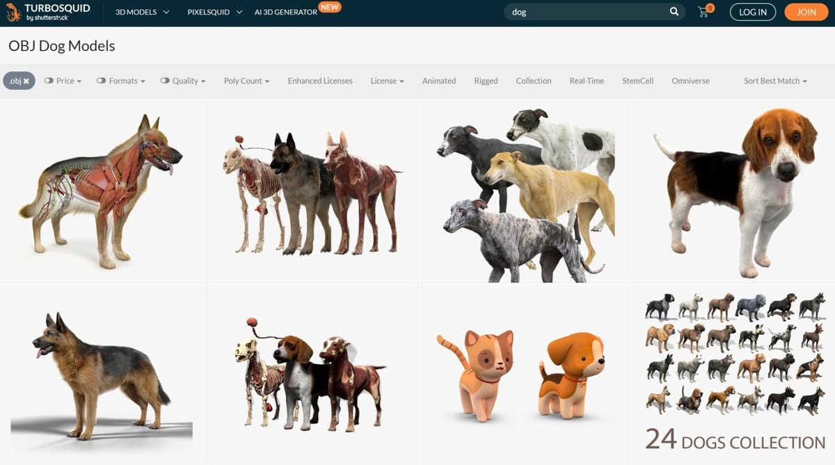
Downloading
There are many repositories, marketplaces, and search engines on the web with hundreds of thousands of free files for you to 3D print. Some major hubs for downloading OBJ files are TurboSquid, Free3D, CGTrader, Clara, and The Free 3D Models, among many others.
Opening & Viewing
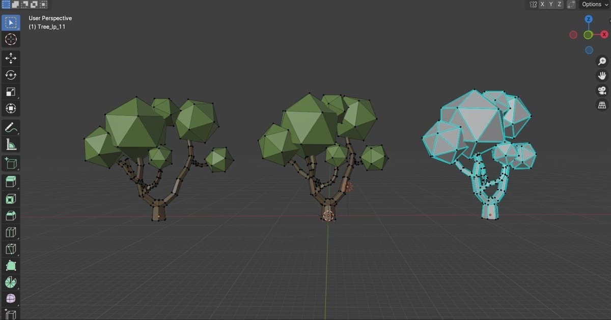
Fortunately, opening an OBJ file isn’t too complicated. Most CAD programs can handle the OBJ file format and will let you view it. Solidworks, Fusion 360, Blender, Rhino, Cinema4D, and Unity all have good reputations.
You can also view the files online without the hassle of downloading and installing software on your machine. Autodesk360Viewer, 3DViewerOnline, or 3D-Tool are some online 3D model viewers that support the OBJ file format.
Repairing
There are several programs that can help repair broken OBJ files. Meshmixer and Meshlab are great tools for repairing the most common printing problems, though the former is no longer being developed but is still available for download.
FAQs
Lastly, we’ll go over some pretty common questions about the OBJ file format and 3D printing.
Can I Do Full-Color 3D Printing Using an OBJ File?
Theoretically, you could use the OBJ file format to create a full-color 3D print. There is a problem, though. Unfortunately, this technology seems to be some way off from being accessible for now. At the time of writing (winter 2023/24), the only existing full-color 3D printers you might want to consider work with either material or binder jetting technology and carry a hefty price tag. There has been an attempt at desktop full-color 3D printing in the past, but the product line is now discontinued and turned out to be pretty awful machines.
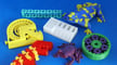
The OBJ file format absolutely supports multicolor 3D printing. As mentioned, the standard 3D printing STL format doesn’t support colors, and the other formats like AMF and VRML are still too fringe to consider for mainstream use. 3MF, on the other hand, is gaining traction in this arena, with many industry players backing it to become the new file standard. And while full-color printing still seems to be some way off, multicolor printing has taken center stage. Prusa Research’s XL printer with up to five extruders and Bambu Lab’s automatic material system (AMS) for the X1 and P1P, which supports up to 16 different colors in one print, show that multicolor printing is achievable and, more importantly, affordable.
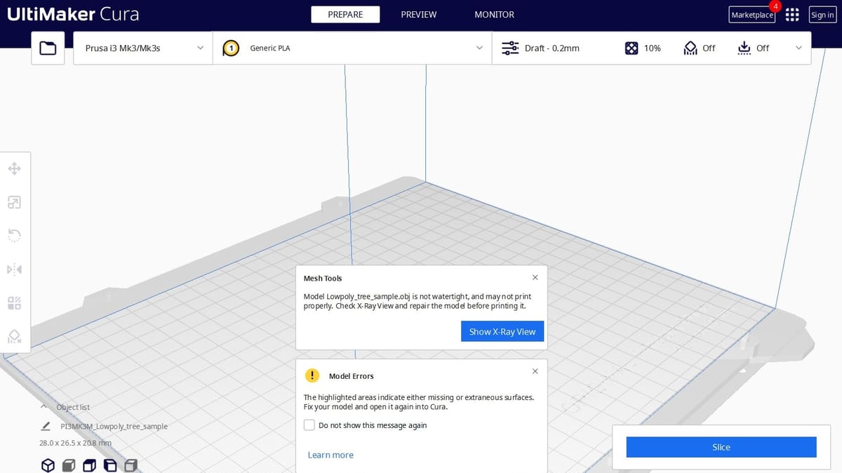
How Is It 3D Printed?
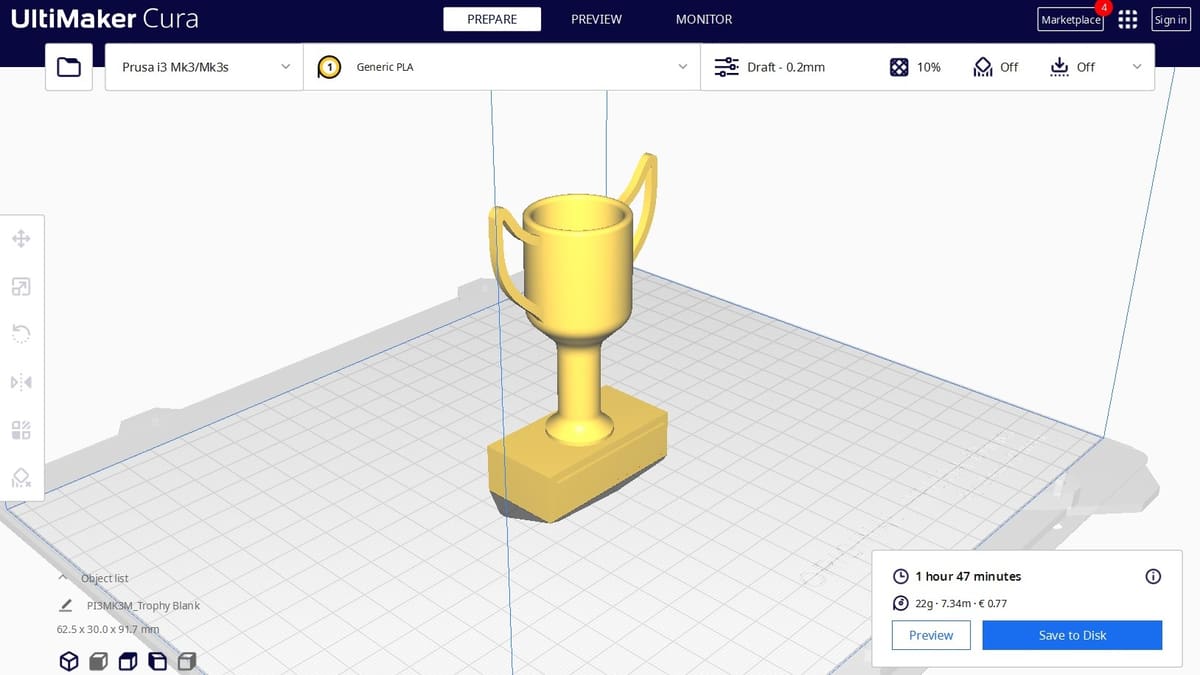
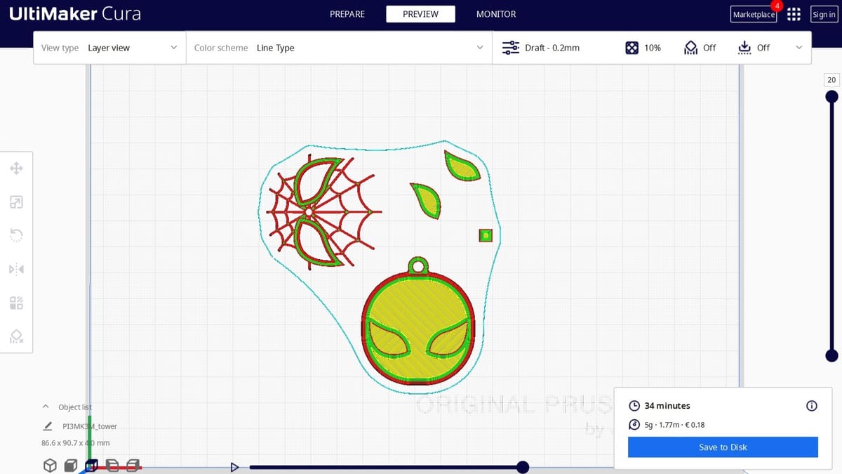
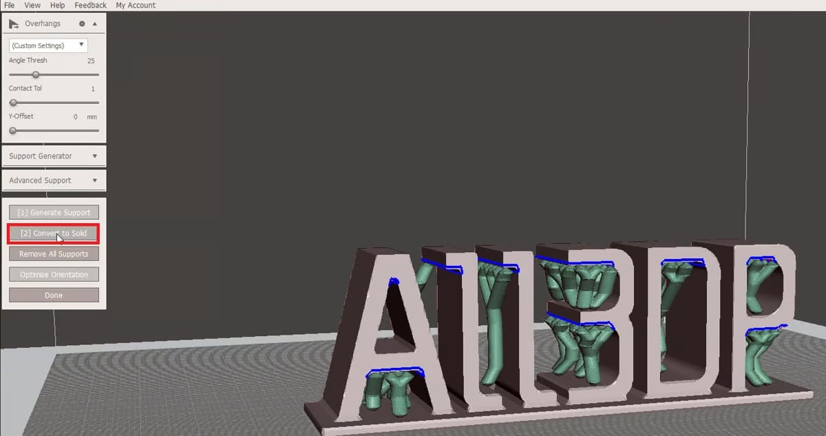
For 3D printing, file types like OBJ need to be loaded into a dedicated slicer like Cura. A slicer is a piece of 3D printing software that converts digital 3D models into printing instructions for your 3D printer to create an object.
The slicer chops up your OBJ file into hundreds (sometimes thousands) of flat horizontal layers based on the settings you choose and calculates a tool path to follow that will physically render your model, layer by layer. This process also calculates estimates for how much material your printer will need to extrude and how long the printing will take.
All of this information is then bundled up into a G-code file, the native language of your 3D printer. Slicer settings impact the quality of your print, so it’s important to have the right software and settings to achieve the best print quality. It’s also important to check if your slicer supports OBJ files and, if so, which features it supports. Some slicers might support simple polygonal meshes but fail if you use freeform curves or surfaces in your encoding.
Are All OBJ Files 3D Printable?
Unfortunately not. Only a 3D design that’s specifically made for 3D printing is 3D printable. The OBJ file is just the container for the data, not a guarantee that something is printable. Keep in mind that OBJ files are also used as an interchange format for 3D graphics applications, a use case that has nothing to do with 3D printing.
3D models suitable for 3D printing need to have a minimum wall thickness and a “watertight” surface geometry to be 3D printable. Even if it’s visible on a computer screen, printing something with a wall thickness of zero is impossible. When downloading a file you didn’t create yourself, it’s worth verifying that it is indeed 3D printable. This will save you a lot of time, frustration, and wasted filament.
License: The text of "The OBJ File Format – Simply Explained" by All3DP is licensed under a Creative Commons Attribution 4.0 International License.