Meshmixer Tutorial for Beginners

Meshmixer is a powerful program for working with meshes. Check out our Meshmixer tutorial to get started with this software!
Meshmixer is a free Autodesk program, compatible with both Windows and MacOS, that’s aimed at working with 3D meshes. As of September 2021, Autodesk stated that they will no longer develop or support the program – but it’s still usable. However, if you need more backing, many of the features can still be found in the capable and powerful Fusion 360, and more mesh features have been promised.
In contrast to the customarily solid CAD models, polygon mesh 3D models are represented by faces, edges, and vertices that, together, define the spatial shape of the object. Such mesh representations may already be familiar to 3D printing enthusiasts: The STL format is a triangular mesh representation, and 3D scans also use polygonal mesh forms to represent objects.
These particular representations can’t be easily worked on in traditional CAD software, and this is when Meshmixer comes in handy. It has tools and features that allow for more or less the same editing capabilities as CAD programs. Further, Meshmixer was developed specifically for 3D printing applications.
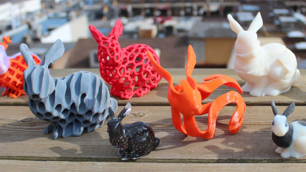
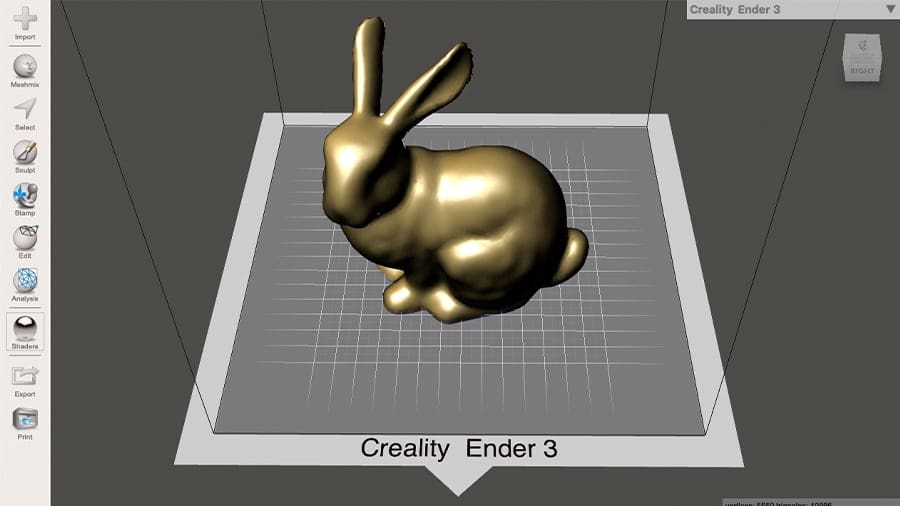
With beginners in mind, this article will walk through the initial steps in editing and correcting a mesh file, taking you all the way to making the final adjustments for 3D printing. This tutorial will use the “Stanford Bunny,” a Meshmixer standard model from a 3D scan of a ceramic figurine, as our example.
Let’s get started!
Getting Started
In this section, we’ll go over the first steps for using this great tool. These steps include importing an external model, learning the UI basics, and viewing modes.
But first things first, download and install Autodesk Meshmixer if you haven’t done so yet.
Step 1: Importing a Mesh
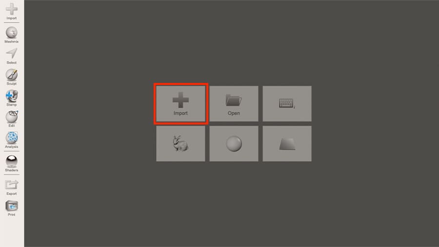
Once you’ve properly installed and opened Meshmixer, you’ll be greeted by the opening screen with some starting action buttons.
The Import button will bring into Meshmixer an external mesh file of your choice. All of the most common mesh formats are supported (STL, OBJ, PLY, AMF, 3MF, OFF, and MIX).
You can also simply drag-and-drop the mesh files into the edit space and either replace the current object or append to the model.
Step 2: Adjusting the XYZ Orientation
By default, Meshmixer uses a somewhat different XYZ orientation than what we’re used to with 3D printers: The axis responsible for the model height is the Y while the ground plane is the XZ. (In the 3D printing world, the Z-axis is usually the build direction.)
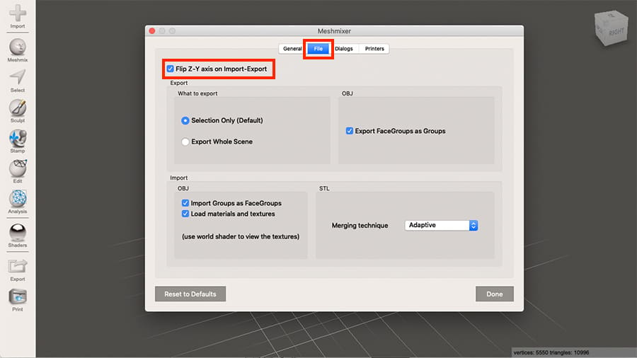
Since most Meshmixer applications involve 3D printing at some point, it would be nice to have the same XYZ orientation as 3D slicers. While we can’t change Meshmixer’s environment orientation, we can change the model’s default orientation during file export. This will ensure that the model, once imported into the 3D slicing software, has the same orientation as the slicer.
- Select “Preferences” from the File menu.
- Select the File tab in the newly opened window.
- Enable “Flip Z-Y axis on Import-Export”.
- Click “Done”, and you’re all set for now.
Step 3: Understanding Camera Controls
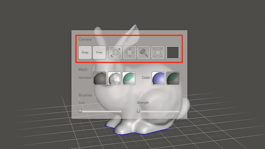
Be it CAD software or 3D printing slicers, every 3D environment offers a set of functions to adjust the user’s “camera” view. For Meshmixer, the options include the following:
- Pan: Hold the center mouse button while moving the mouse to pan across the current plane.
- Zoom: Use the mouse’s wheel to zoom in and out, or press Alt (Option for Mac) + the right mouse button and move up and down.
- Orbit: Hold down Alt + left mouse button, or only the right mouse button to orbit around the center of the coordinate system. Another option is to hold Shift + the middle mouse button.
You can also access all these tools by holding down the space bar. A menu appears, and the desired tool can be selected from the camera options: Click the desired tool and hold down with the left mouse button to select it.
If you end up losing your model in the vast 3D environment, which happens from time to time, select “Recenter View” from the View menu to focus on the center of the coordinate system once again.
Step 4: Positioning & Scaling a Model
There are two ways you can position and scale the model in Meshmixer: the Transform tool panel or the 3D transform widget.
Transform Tool Panel
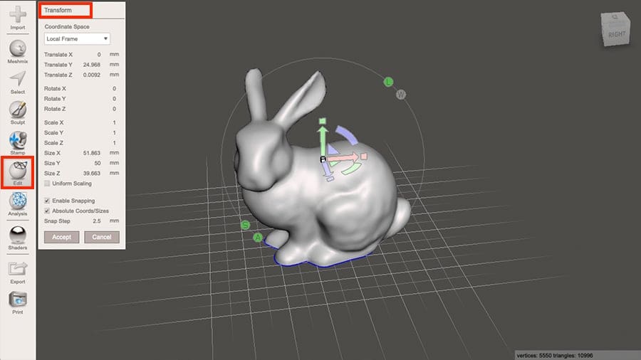
- Press the Edit button on the left side panel and select “Transform” from the menu. A small side window, the Transform tool panel, will pop-up with all translation and scaling tools.
- Choose between “World Frame” or “Local Frame” coordinate spaces. (All positioning will be in relation to the referenced coordinate system selected here.) The “World Frame” is defined by the center of the coordinate system in the build space, while the “Local Frame” has the model rotation referenced by the coordinate system of the object selected.
- Enter the values for the desired transformation directly in this window for precise transformation. Options include translation, rotation, scaling, and sizing, for any given axis.
3D Transform Widget
Rather than entering values in the Transform tool panel, you can use the mouse to click and drag on the colored icons via the 3D transform widget that appears on the model.
- Press the Edit button on the left side panel and select “Transform” from the menu. The 3D transform widget should appear on the model.
- Use the widget’s handles to transform the model as desired.
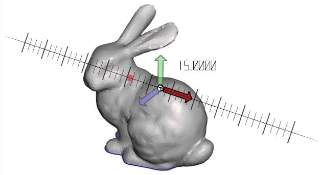
- Click and drag one of the arrows to move the position of the object alongside that axis.
- Click and drag the colored arcs to rotate the object.
- Click and drag the white cube in the center to scale the model uniformly, or, to stretch the model in a given direction, click and drag the colored square at the end of each arrow.
- Click and drag the colored triangles to shift the model alongside a plane.
Checking “Enable Snapping” at the bottom of the Transform tool panel allows you to control these transformations in incremental “Snap Steps”, which can be pre-defined by entering a value based on whatever level of accuracy you need.
Step 5: Selecting Shaders
Meshmixer offers different object view modes, called Shaders, that control the appearance of the 3D models.
- Click on the Shaders icon on the left panel to open the small window with all the Shader options. The options appear as globes in the menu.
- To apply a Shader to an object, select and drag it from the menu onto the desired object.
Useful Shaders for 3D Printing
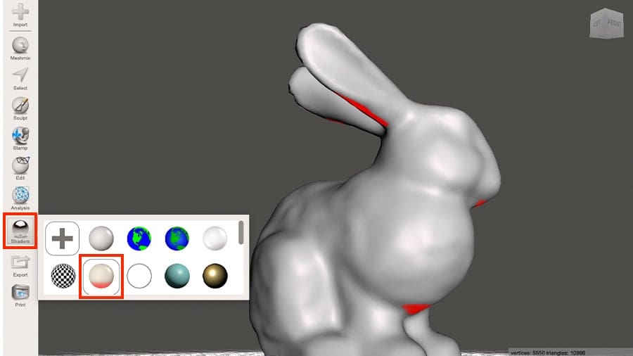
The default and Overhang Shaders are particularly useful for 3D printing.
- Default: This Shader is the first option in the menu, and it displays the model’s inside surfaces in a light reddish color. This is very helpful for spotting non-manifold areas, which need to be corrected prior to any 3D printing.
- Overhang: This Shader is represented by the sphere with the red bottom. When using it, the regions of the model that might require supports during 3D printing will be highlighted in red.
Step 6: Customizing the Print Space
In Meshmixer, the 3D environment can be customized to match the build platform of specific 3D printers. This is especially useful when handling multiple objects that will be printed in one job.
You can see the printer bed in the 3D environment by checking “Show Printer Bed” in the View menu. To disable the display of the print space, simply uncheck this option in the View menu.
Setting up a customized print space can be done in two ways, either by selecting a pre-defined printer in Meshmixer or adding a new one manually.
Pre-defined Printer
You can browse through the printer selection widget to check if your 3D printer is pre-programmed in Meshmixer.
- On the top right corner, click on the downward arrow to open the list of common 3D printers.
- Browse through the manufacturers and select the 3D printer model by simply clicking on it.
The 3D environment will be updated, and the build plate size will be adjusted accordingly.
Adding a Printer
In case your 3D printer isn’t on the list, you can manually input the print volume dimensions.
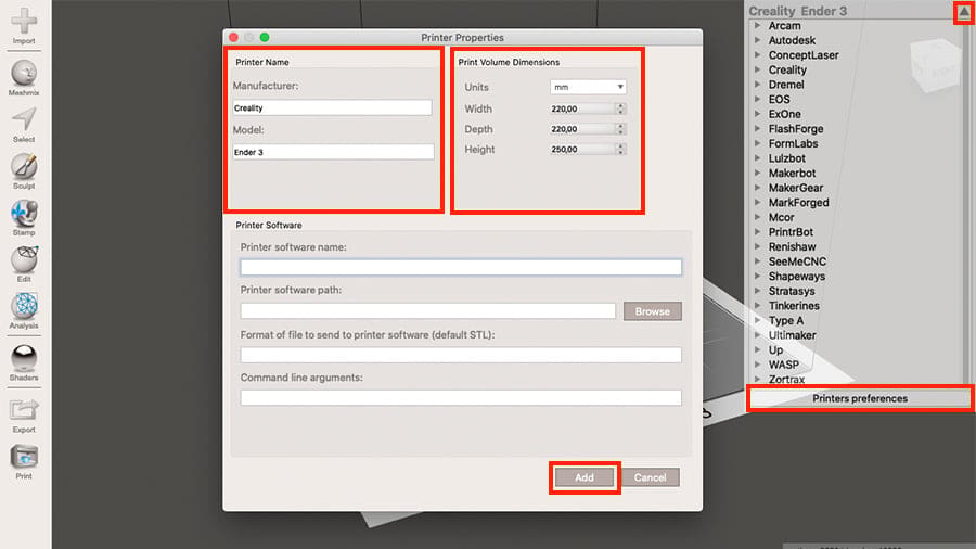
- Select “Printer Preferences” at the bottom of the drop-down 3D printer list. The Printers tab will open.
- Click on “Add”.
- Fill in the “Manufacturer” and “Model” fields on the top left.
- Adjust the build volume size under the “Print Volume Dimensions” section on the top right.
- Click on “Add”, and the print space should be updated. The newly added printer will also be added to the drop-down list of 3D printers.
Working the Model
Now that we’re acquainted with Meshmixer’s basics, let’s go over the main tools and features for working on the model and getting it ready for 3D printing.
One of the program’s most popular capabilities is that it can analyze and correct defective meshes, but also noteworthy is the ability to add escape holes and create customized tree supports.
Step 7: Finding & Repairing Mesh Defects
3D models from websites such as Thingiverse and MyMiniFactory are usually created by the user community and sometimes come with defects. It’s also very common to find defects in 3D scanned data. These mesh issues must be dealt with prior to even thinking about 3D printing.
Meshmixer offers both automated and manual tools for correcting mesh tears and holes. Let’s start by looking at the automated way.
The Inspector Tool
One simple way to locate and correct defects is to use the Inspector tool.
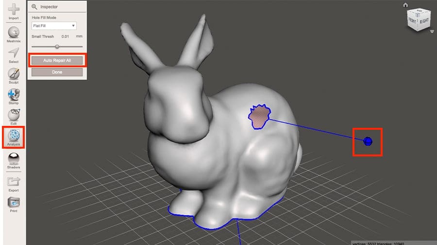
Press the Analysis button on the left panel and select the Inspector tool from the menu. The analysis will run automatically on the selected model(s). Once computed, any mesh issues will be highlighted in different colors pointing out potential holes and gaps.
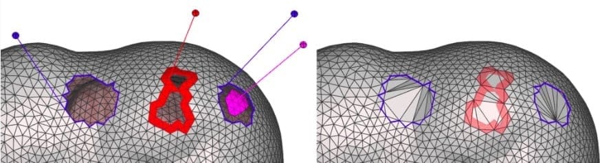
The colors symbolize the overall severity of the issue:
- Blue indicates a minor error, which can easily be patched.
- Red stands for larger defects.
- Pink indicates an island, a completely separate body that will be removed during the first step of repairing.
Meshmixer usually does a good job fixing all found issues regardless of the severity. Click on a single ball sign to fix errors individually, or click on “Auto Repair All” in the Inspector tool panel to do it automatically.
It’s always a good idea to check the repaired areas after the process and even to run the Inspector tool a second time.
Step 8: Creating a Flat Surface
Some models, especially those obtained via 3D scanning, might not display a good flat surface. Good bed adhesion is critical for successful 3D printing, and it’s fairly simple to accomplish in Meshmixer.
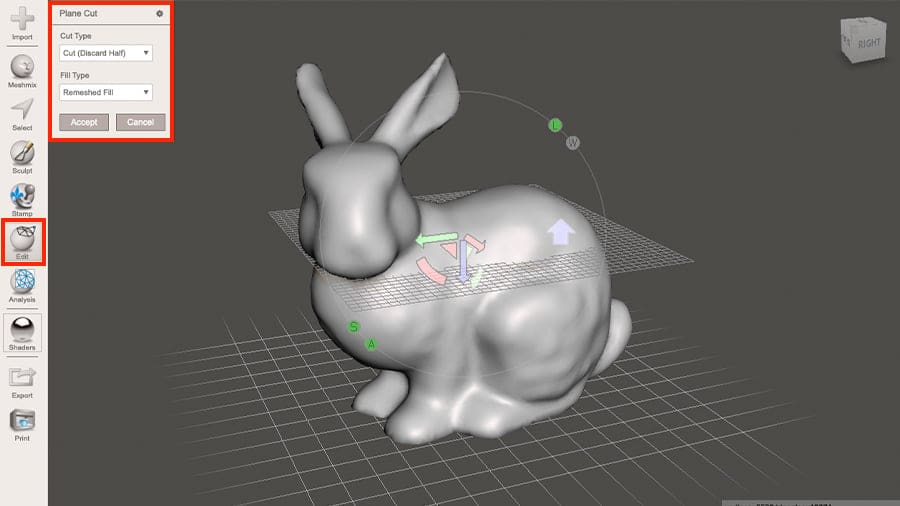
The Plane Cut is a fast tool that can be used to create a smooth and stable surface to print on.
- Press the Edit button on the left side panel and select “Plane Cut” from the menu. Once selected, a plane is displayed in the model along with moving icons similar to the 3D transform widgets.
- Move and rotate the plane around in relation to the object and position it where the flat surface is desired. The wider blue arrow indicates the direction of the part that’s being cut out.
- If desired, click on this arrow to switch the direction of the cut.
- Once the plane is properly placed, click “Accept” in the Plane Cut tool panel, and the surface will be created accordingly.
Step 9: Hollowing & Holing
Sometimes it can be a good idea to hollow 3D models in order to save time and material when 3D printing. This is a popular strategy with resin printing since the feedstock material can be quite expensive. For these processes, the unused liquid resin will remain inside the model unless we create escape holes.
Folks at Autodesk are aware of this, and Meshmixer has a special tool designed for doing both things:
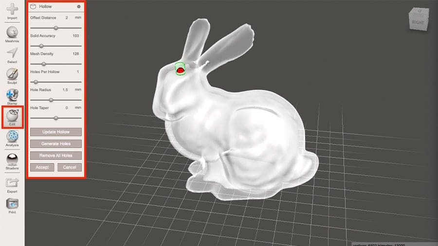
- Press the Edit button on the left side panel and select the Hollow tool from the menu. After processing, the object may be see-through so as to represent the hollowed-out area.
- Adjust the tool’s settings as desired, which include the following:
- Offset Distance: This will determine the wall thickness of the final model. We recommend that you adjust the thickness according to the slicer properties of your 3D printer.
- Solid Accuracy and Mesh Density: These settings will improve the smoothness and accuracy of the internal surface. Both of these settings are set according to 8-bit, meaning that 256 is somewhat equivalent to 100% accuracy. Note that the higher you set these values, the longer processing will take.
- Holes Per Hollow, Hole Radius, and Hole Taper: “Holes Per Hollow” will set the total number of escape holes in the model, with their sizes defined by “Hole Radius” and “Hole Taper” settings, in millimeters.
- Click “Generate Holes” to display the desired number of holes.
- Click and drag the spheres around the surface of the model to place the escape holes where desired.
- With all the above set, click “Accept”.
Step 10: Creating Automatic & Custom Supports
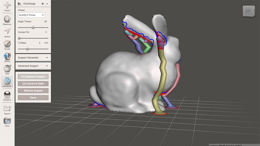
Meshmixer offers great tools for creating support structures for 3D printing. While most (if not all) 3D slicers offer the same capabilities, Meshmixer allows the creation of a different kind of structure: tree supports. These are not offered in all slicers, although you’ll find them in Cura and PrusaSlicer. In contrast to standard lattice structures, tree supports are desirable because they require less time to print and are an efficient way to use the materials.
The automatic support feature will create support structures for the areas highlighted by the Overhang Shader we mentioned earlier, and this can be a very good starting point for a more customized approach. This very rich feature has an in-depth review and tutorial of its own.
Preparing to 3D Print
With the model duly edited and ready for materialization, it’s time for the final checks that should make your life much easier during slicing and printing.
Step 11: Checking the Final Model's Placement
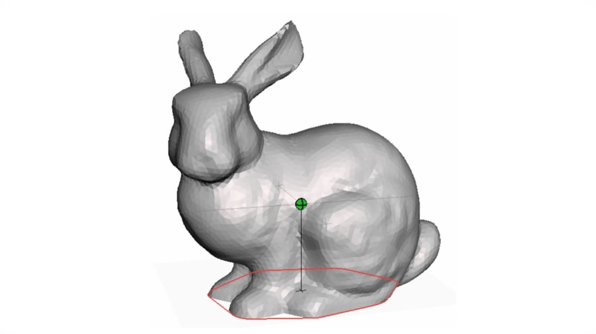
It might be a good idea to double-check whether the model is flat on the build table after all the transformations we did. Meshmixer’s Stability tool will calculate the total surface area, the volume of the object, and will also outline in red the contact area between the model and the ground plane.
Furthermore, Meshmixer will tell you whether this current position might tip the standing object. A red dot in the middle of your object will indicate an unstable position, meaning that the model needs to be repositioned in the build table. A green dot indicates a stable position.
To do the stability check, press the Analysis button on the left side panel and select “Stability” from the menu.
If your model’s unstable, there’s a great trick to place the model perfectly onto the ground plane without spending too much time with the Transform tools:
- With the model selected, press the Edit button on the left side panel and select “Create Pivot” from the menu.
- Set the “Placement Mode” drop-down menu to “Surface Point”.
- Set the “Coordinate Frame” drop-down to “Geometry Frame”.
- Click on the plane of the model you want to align with. This will place a pivot that functions as an independent coordinate system.
- Click on “Drop Pivot” to confirm the placement.
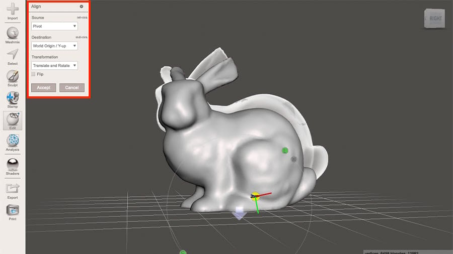
- Now press the Edit button on the left side panel and select the Align tool from the menu.
- Set the “Source” drop-down to “Pivot”.
- Set the “Destination” drop-down to one of the “World Origin” coordinate axes (“Y-up” is usually the one).
- Click on the pivot on the model you placed during step #5. The model will be updated to the new position.
- Click “Accept” in the Align tool panel to confirm the new position.
Check the placement of your model by using the Stability tool again. It should now be placed perfectly aligned with the ground plane.
Step 12: Checking Wall Thickness
In case the model has been hollowed out as shown in step #9, you might want to ensure that the object shell has an adequate uniform thickness for 3D printing. Although we’ve set the Offset Distance to define the wall thickness of the final model, in reality, that might not be consolidated. To check that, we’ll use the Thickness tool.
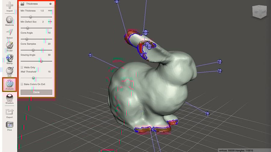
- Press the Analysis button on the left side panel and select “Thickness” from the menu.
- Set the “Minimum Thickness” according to your own requirements and 3D printing capabilities. Meshmixer will automatically highlight the areas thinner than specified.
In our example, the bunny has been hollowed with an Offset Distance of 2 mm. The Thickness analysis, however, shows in red the areas where the thickness measured less than 1.5 mm.
Depending on each model’s requirements, it might be a good idea to hollow the object with a thicker Offset Distance to ensure enough thickness across all areas of the model.
Step 13: Exporting & 3D Printing
Now the 3D model should be optimized for 3D printing. You can export the model by clicking the Export icon on the left panel. You have the option of several supported file formats, including the popular STL. Before you print the model, however, it still requires traditional slicing in any other program of your choice.
With that, you’ve completed your very first steps in Meshmixer. Congratulations!
In addition to the tools and features we reviewed in this tutorial, this powerful software offers many other capabilities, such as 3D modeling from scratch and manual editing tools.
License: The text of "Meshmixer Tutorial for Beginners" by All3DP is licensed under a Creative Commons Attribution 4.0 International License.