How to Set Up & Edit Marlin Firmware

You may want to want to use Marlin 2.1 on your 3D printer, CNC machine, or robot. Read on and learn how to edit Marlin firmware!
Every 3D printer, regardless if homespun or bought, has a microcontroller board. And residing in that board is a computer program that translates G-code into movements and extrusions, deals with various sensor inputs, and controls other aspects of the machine. This is the printer’s firmware. While we have a choice of other interesting open-source firmware options, like Klipper and RepRap, Marlin is an established favorite among makers.
Its popularity is partly due to the great community support that constantly improves Marlin with new features. Another reason is the fact that it’s deployable for a variety of different machines, such as CNC mills and lathes, laser cutters, and more. Upgrading to the latest version requires some knowledge, but even beginners should be able to accomplish it.
In this article, we’ll cover the latest stable version – Marlin 2.1 – released in June, 2022. In particular, we’ll go over important configuration points like using the correct motherboard, adjusting mechanical and thermal settings, and how to get started, demonstrated for a single-extruder CoreXY printer.
While you may have a different type of machine, there’s still plenty to learn about Marlin, so read on!

Why Upgrade?
As time goes on, 3D printer enthusiasts may want to tinker with the machine to open up more features, to speed it up, to improve the printing quality, or for a little bit of everything. With capable 32-bit hardware coming down in price and many users still operating the fairly old-fashioned Arduino Mega and Ramps 1.4 setup, or boards based on it, the temptation to throw out the old and get a nice new controller board grows.
Yet, understandably, it might cause some anxiety to move away from a company-branded and printer-customized firmware setup – a change that would most certainly invalidate warranty claims you may have if the printer is still new. Therefore it’s recommended to check such things before tinkering. While it’s unlikely that you’ll break something, you may want to consider how much support you’ll need to restore your firmware should something go wrong.
If you’re comfortable with moving forward, the future is bright. More processing power translates into a smoother experience, (potentially) more sensor inputs, and a printer that can more easily deal with added calculations, such as linear advance, bed mesh probing and fading, and more.
Know that, for every new addition, you’ll need to adjust your printer’s firmware. Meanwhile, having a basic understanding of the firmware will help you diagnose issues, improve hardware, and let you access new features.
Before we get to updating the firmware, though, let’s see what’s needed.
Basic Requirements
Before you install new firmware on a 3D printer, you need the following:
- A PC, mouse, keyboard, and USB cable
- A 3D printer with a Marlin-compatible motherboard
- Visual Studio Code with Platform IO and optionally Marlin Auto Build installed on your PC
- (For LPC-1768-based boards) A 32-GB SD card
We won’t cover how to set up your build environment here, but the links above should do the trick.
Since Marlin version 2.0, PlatformIO on Visual Studio Code (VSC) is the recommended build environment for all Atmel AVR 8-bit and 32-bit ARM microcontroller boards. While using Arduino IDE still works for AVR processor boards, users have reported problems with compiling the firmware. The older boards will still benefit from many bug fixes and improvements, but due to memory restrictions, they’re limited in terms of how many new features can be used with the latest Marlin release.
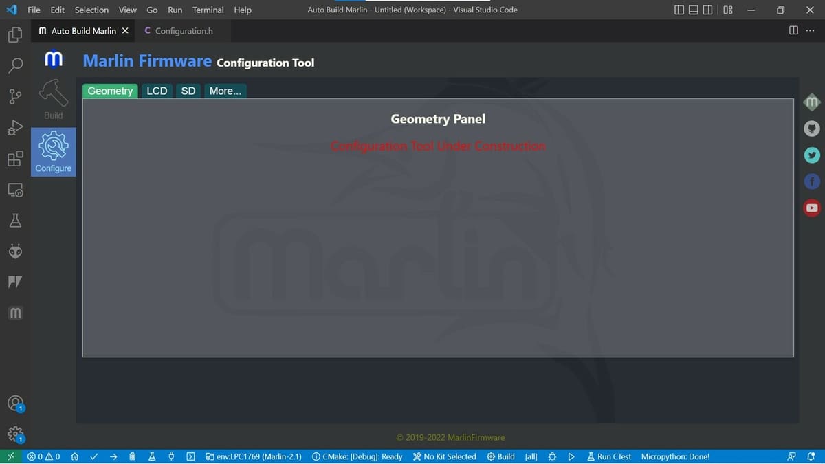
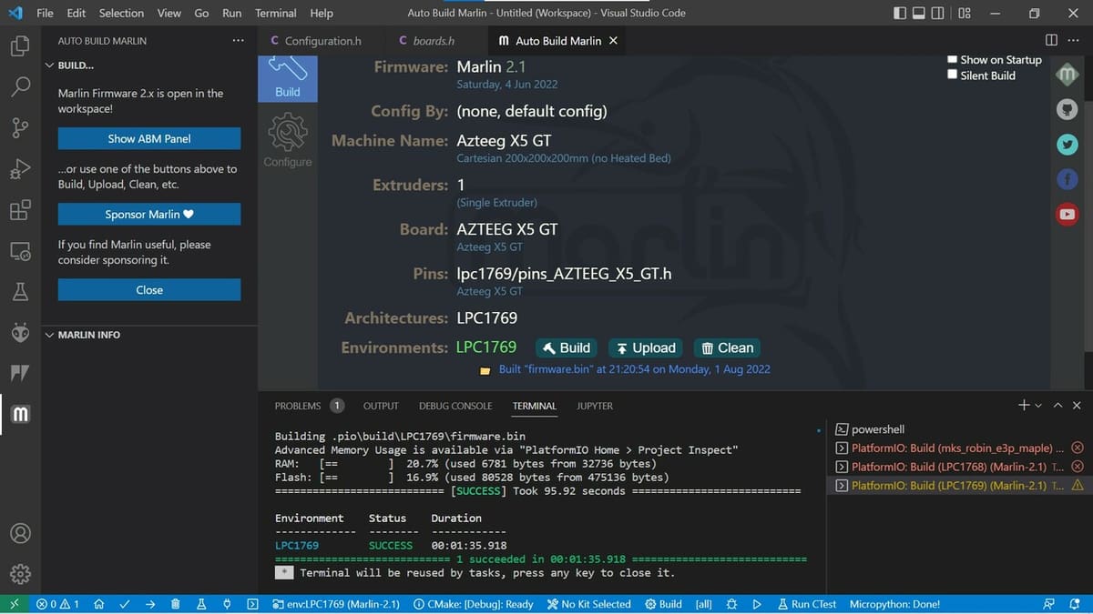
For those unfamiliar with VSC and PlatformIO, Marlin offers a few simple instructions, including a detailed guide on how to set up and use the Auto Build extension. This extension makes it a little easier to configure PlatformIO for building the firmware project. (See the tip in the next section).
Note that Auto Build extension may seem unfinished with respect to some of its functionality, such as the configuration option being under construction at time of writing. This is of course a shame, but building, uploading, and cleaning an existing configuration is still possible. With regard to uploading, there’s just one caveat, which is that many 32-bit boards require an SD card for uploading firmware and the upload button doesn’t really do anything.
A Simpler Way to Upgrade
For AVR and 32-bit ARM boards, the firmware can be upgraded as follows:
- Download Marlin.
- Edit the configuration files with your favorite text editor or Arduino IDE.
- Compile the Marlin firmware files into binary code using an integrated development environment (IDE), such as PlatformIO or Arduino IDE.
- Upload the code to the board.
For LPC-1768 based boards, follow the Re-ARM procedure. There are some extra steps to get the board to accept a new firmware upgrade, but the rest follows the above closely.
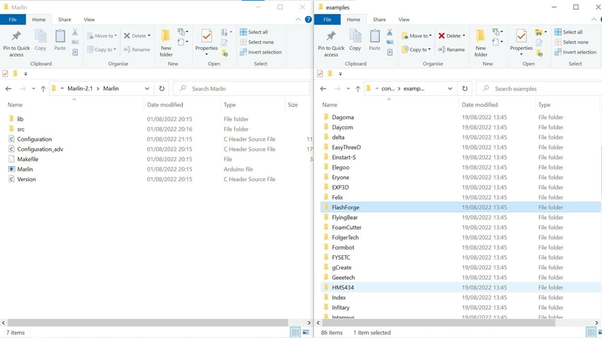
A note about the above: Extracting the Marlin 2.1 zip file reveals two configuration files in the Marlin subfolder: “Configuration.h” and “Configuration_adv.h”. These are the two files which have to be edited for most firmware upgrades. To make your life even easier, there are configuration examples available. Each provides versions of the two configuration files for a specific board. They can simply be copied and pasted into the Marlin subfolder.
Tip
It’s recommended to check if your device is already present as one of the configuration examples. If it is, make sure to copy both configuration files to the Marlin subfolder before opening them with PlatformIO. Marlin Auto Build automatically recognizes your configuration and allows you to choose from different processor versions if applicable. Push the Build button to check that all is well before editing anything. Try again if it fails the first time… It can happen.
After a successful trial build, open the configuration files in the text editor of your choice to check and eventually edit the settings for your printer as indicated in the rest of the article.
Getting Started
Before any firmware upgrade, it’s wise to collate all the information required. Knowing the exact bits and pieces of hardware in your machine is essential not only for upgrading but also for troubleshooting later.
Before you start tinkering with firmware, take note of what you have:
- Type of FDM printer: Cartesian, CoreXY, delta, robotic arm, etc.
- Type of controller board: Ramps 1.4, MKS SBASE, SKR Pro, etc.
- Type of drivers used: A4988, DRV8825, TMC2160, etc.
- Type of display used: Full Graphics Controller, LCD, etc.
- End stops: How many? On which axes? (Understand the maximum and minimum positions for your printer.)
- Thermal sensors: Type for heated bed and extruder
- Extruders: Type, number, etc.
- Type of probe
- Dimensions of your printer: Maximum travel in every axis, offsets between nozzle and probe, etc.
As mentioned, we’ll explain how to configure the basic settings of a single-extruder CoreXY printer because most will have a Cartesian printer, which will have most of the following settings by default. By checking out a CoreXY’s firmware update, we won’t be limited to fewer settings.
Importantly, we won’t look at every section of the configuration file, but anyone should be able to edit the file successfully with the general knowledge gained from the following. This will allow you to understand the structure and philosophy behind Marlin’s firmware configuration and thus allow you to adjust it to your needs.
Initial Configuration
When working with firmware, it’s important to keep track of the changes you make. Towards that end, the “info” section at the beginning of the code allows you to add any text you like within the double quotation marks. Entering the date and the type of changes made can help you keep track of your machine settings instead of having to go through the code again. Note that this doesn’t affect the code and won’t be displayed when the machine starts running.
Now, let’s enter the “machine” section. By default, the baud rate is set at the standard 250,000. This is the speed of communication between the computer and your controller board when connected via USB. It’s important to be aware of this value, as you’ll be prompted to choose a baud rate to connect to host software, such as PronterFace or Repetier Server. Some controller boards only accept certain baud rates for communication, such as the Ramps 1.4 and Mega combo, which only accepts up to 115,200.
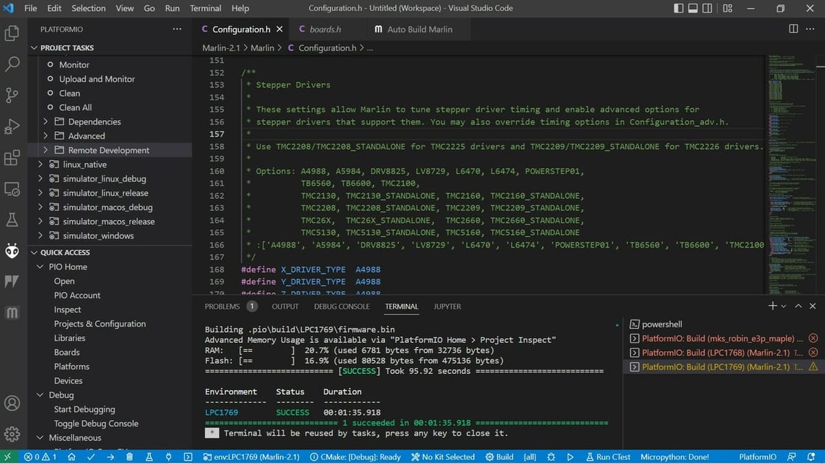
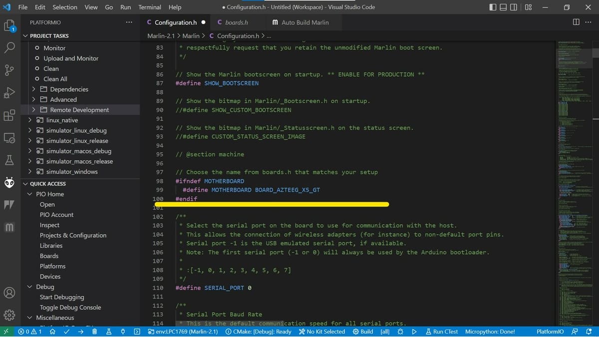
Next, you’ll have to select the controller board that you’re using. This is important, as it will decide the mapping of input and output (I/O) pins. The default is Ramps 1.4, with an extruder, a fan, and a heated bed as 12-V outputs. In PlatformIO, open the “src/core/board.h” file and find your board in the list. Importantly, if you followed our above tip about configuration examples, the motherboard should already be set correctly!
If you’re unable to see it immediately, scroll down. For example, if you’re using an Azteeg board, you can either copy the name of the board that follows “#define” or use the number directly. In this case, the number is 2501, like this:
#define MOTHERBOARD BOARD_AZTEEG_X5_GT
or
#define MOTHERBOARD 2501
Next, you’ll need to set the number of extruders. Since we’re using a single extruder, we enter 1 as the value:
#define EXTRUDERS 1
Finally, let’s indicate the filament diameter:
#define DEFAULT_NOMINAL_FILAMENT_DIA 1.75
Thermal Settings
FDM 3D printers extrude plastic by heating material to temperatures as high as 300 °C. For this reason, every heater comes with a thermistor or thermocouple, a device that measures the actual temperature values in real time and sends feedback to the controller, telling it when to turn the heat up or down. Poorly selected or malfunctioning thermistors can lead to incorrect temperature readings and thus heater malfunctions.
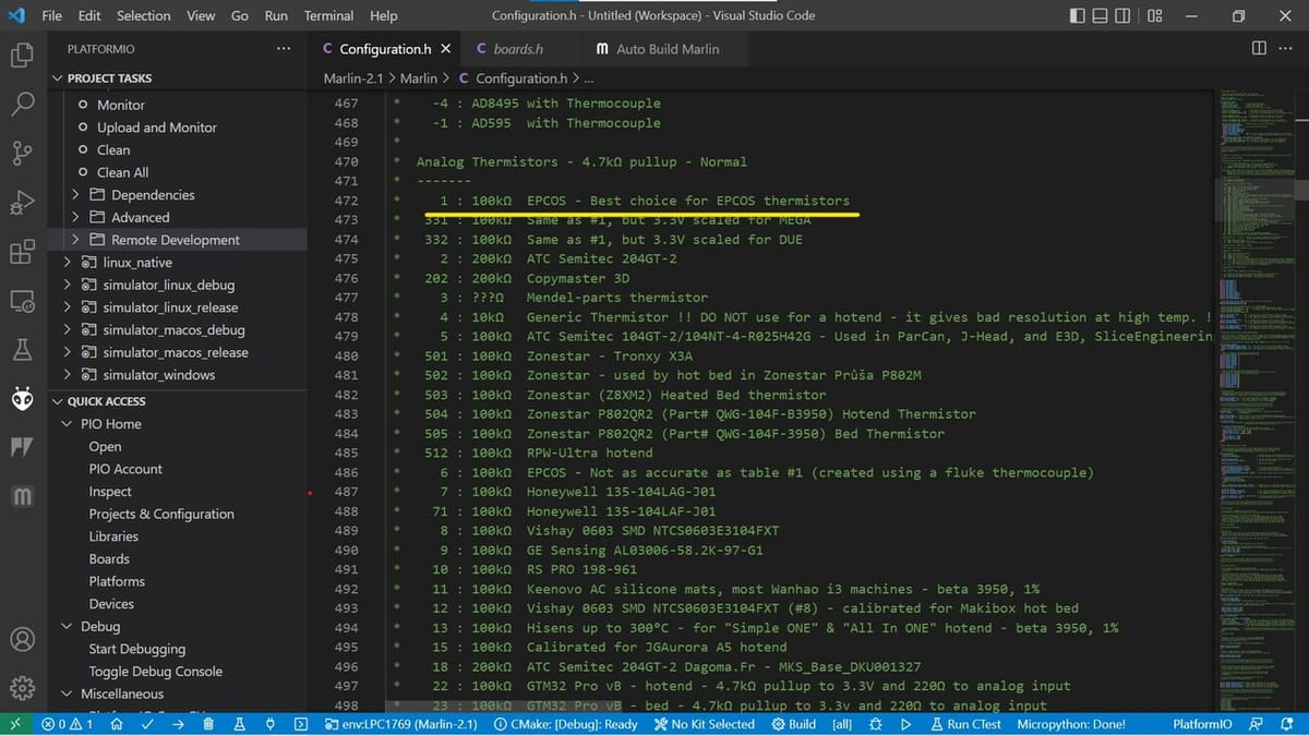
We need to select a thermistor from the list of thermistor types recognized by Marlin. Based on the type of thermistor being used, a corresponding value needs to be plugged in. Typically, the hot end manufacturer provides the specifications of the thermistor. The most common type is a 100-KΩ thermistor with a 4.7-KΩ pull-up, which leads to the corresponding value of 5:
#define TEMP_SENSOR_0 5
If you have a heated bed, select the thermistor for that, as well. Again, the most common thermistor value is 5:
#define TEMP_SENSOR_BED 5
We can skip the PID (proportional integrative derivative) settings, as these are well-calibrated and tuned by themselves.
Next, we come to thermal runaway. These two commands are activated by default, protecting your machine from accidental thermistor failures. To deactivate them, you can add two forward slashes in front. Only do this if you have a good reason to, such as for troubleshooting and verification purposes, and if you know what you’re doing. Never deactivate them and leave the printer alone; this creates a fire risk.
Mechanical Settings
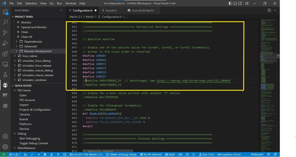
3D printers use motion mechanisms to move the hot end and print bed relative to each other. These mechanisms and their assemblies is what leads to names like “CoreXY” and “H-bot”. Different systems use different mathematical representations to define the motion of the machine. By default, Marlin assumes that you’re going ahead with a standard Cartesian-style 3D printer (also referred to as an XZ-head or i3-style printer).
If you’re using a CoreXY or H-bot system, make sure to activate the appropriate settings. To make life easier, you can download a preconfigured example from the configuration depository on GitHub. Just make sure to edit all of the basic items already mentioned above!
If you don’t find the right example, you can simply activate your configuration by removing the two forward slashes in front of your selection (and adding them to all others). “COREXY” and “COREYX” are most common for CoreXY and H-bot printers. They both share the same fundamental mathematical framework and, hence, a single setting works for either style.
Since we’re using a CoreXY mechanism, this is how our code will look:
#define COREXY
//#define COREXZ
//#define COREYZ
//#define COREYX
//#define COREZX
//#define COREZY
End Stops
The end stop settings let you choose where you want the homing position of your nozzle and bed to be. “XMIN” is the minimum position, which will be 0 in most cases, and “XMAX” will be the maximum position for the axis defined by you.bOnce again, you’ll need to manipulate the forward slashes:
#define USE_XMIN_PLUG
#define USE_YMIN_PLUG
#define USE_ZMIN_PLUG
//#define USE_XMAX_PLUG
//#define USE_YMAX_PLUG
//#define USE_ZMAX_PLUG
By uncommenting the “MIN” position for all axes, you you define all three axes to be homed at their minimum positions (0,0,0).
If you wanted ‘X’ to home at the minimum position, but ‘Y’ and ‘Z’ to home at their maximum positions, the code would look like this:
#define USE_XMIN_PLUG
//#define USE_YMIN_PLUG
//#define USE_ZMIN_PLUG
//#define USE_XMAX_PLUG
#define USE_YMAX_PLUG
#define USE_ZMAX_PLUG
Limit Switches
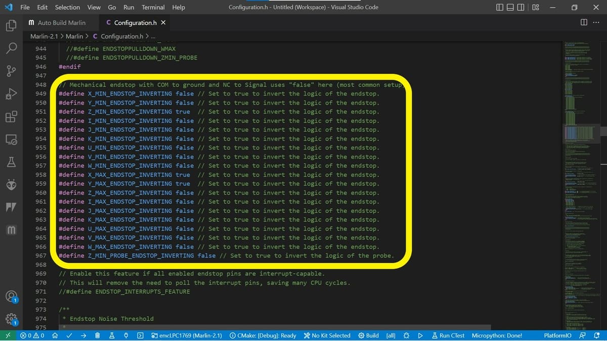
Most limit switches have two basic modes for letting the controller board know whether the switch is triggered or not. The first is “normally closed” (NC) and the other is “normally open” (NO). Depending on how the limit switch is wired, this can vary.
When a limit switch is pressed, it sends a signal to the board based on the type of sensor. Sometimes this signal is inverted, meaning the board assumes that the switch is open when the extruder has reached its home position. If you feel that your end stop isn’t being triggered properly, try inverting the signal:
#define X_MIN_ENDSTOP_INVERTING false // set to true to invert the logic of the end stop
Homing Settings
Scroll down further until you see the “HOME” settings. When an axis homes at the minimum position, the corresponding homing value needs to be -1.
// Direction of end stops when homing; 1=MAX, -1=MIN
#define X_HOME_DIR -1
#define Y_HOME_DIR -1
#define Z_HOME_DIR -1
Build Volume
You’ll also need to define the size of your build volume so as to not accidentally move an axis beyond its limits. These are also the maximum positions that the printer can move.
// The size of the print bed
#define X_BED_SIZE 200
#define Y_BED_SIZE 200

// Travel limits (mm) after homing, corresponding to end stop positions
#define X_MIN_POS 0
#define Y_MIN_POS 0
#define Z_MIN_POS 0
#define X_MAX_POS X_BED_SIZE
#define Y_MAX_POS Y_BED_SIZE
#define Z_MAX_POS 200
Movement Settings
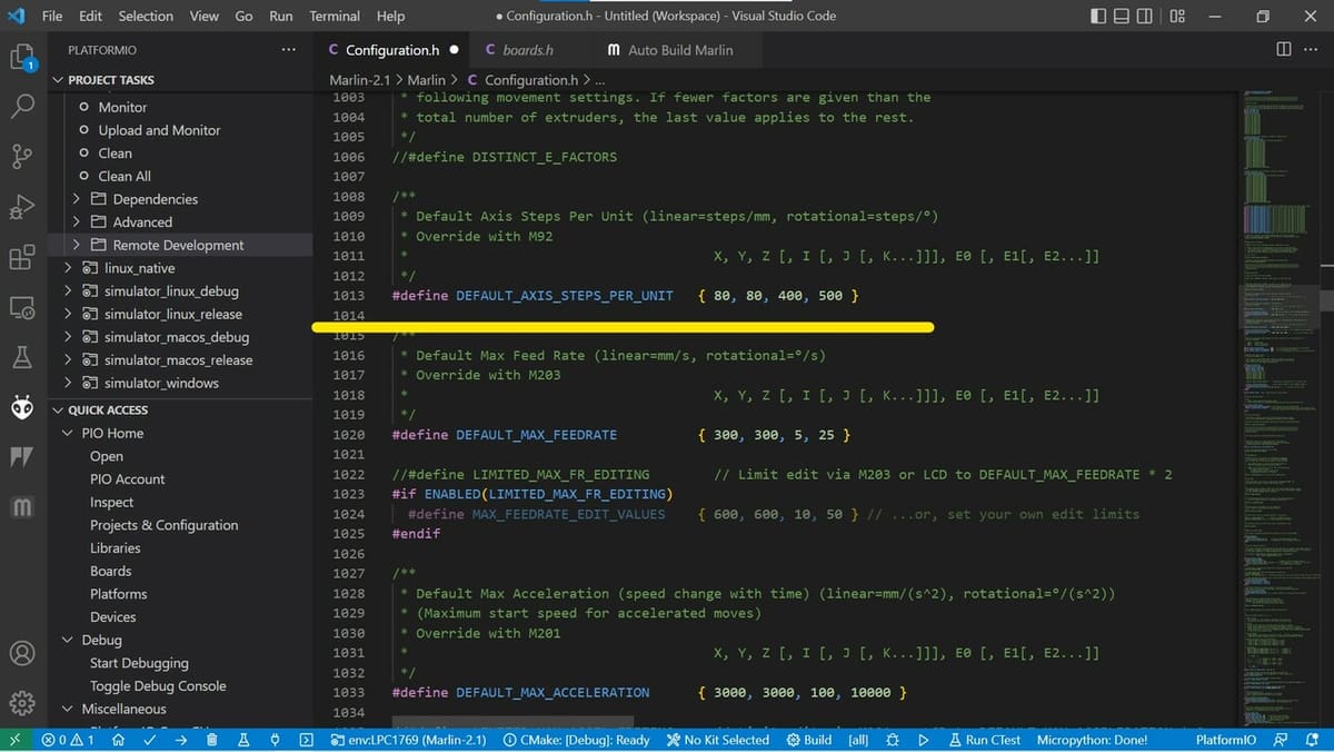
Steps per unit is the only setting that we will deal with in the “movement” section, but that doesn’t mean it’ll be easy… To ensure that your printer exactly moves the specified distance, we’ll need to calculate the “steps per mm” value for each axis.
Steps per mm means the number of steps a motor has to make for your machine to move by 1 mm along a particular axis. Thus, this value needs to be calculated for each of the X-, Y-, and Z-axes and for the extruder mechanism. This is the line of code that we will need to modify:
#define DEFAULT_AXIS_STEPS_PER_UNIT { 80, 80, 4000, 500 }Most machines use a belt for the X- and Y-axes and a lead screw to lift either the printhead or the print bed. Making things easier are online calculators, like the the Prusa calculator. Scroll down to the stepper motors section, which has a belt-driven section and a lead-screw-driven section.
Belts
For belts, there are four values you need to know to figure out the steps per mm:
- Motor step angle: For most NEMA 17 motors, this will be 1.8°. To be sure, check the documentation provided by the motor’s manufacturer.
- Driver micro-stepping: Most boards out there use 1/16th micro-stepping, but in general, this information will be provided by your board manufacturer. If you bought the stepper sticks separately, you can check with your supplier. Some stepper sticks can do 1/32, with others going down to 1/256. The higher the number in the denominator, the smoother and more precise your steppers are going to be. Make sure not to go above 1/16, as the motion gets jerky and rough.
- Belt pitch: If you’re using standard GT2 belts, then the pitch will be 2 mm. Otherwise, make sure to check the specifications.
- Pulley tooth count: GT2 pulleys come in a few varieties, with between 8 teeth and 20 teeth.
Once all values are entered, the final value is automatically calculated.
Lead Screws
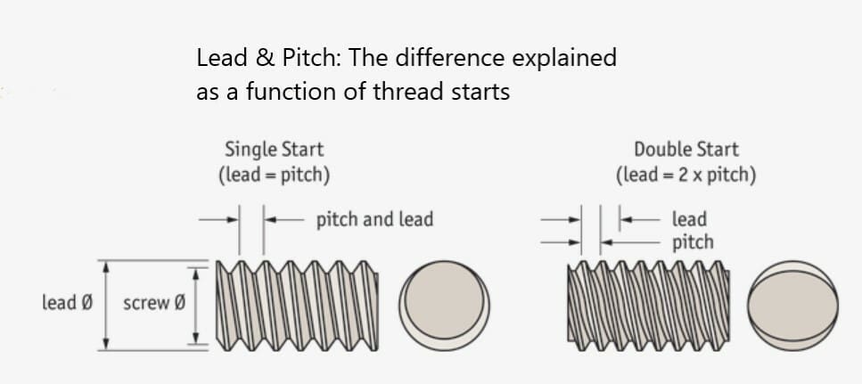
For the Z-axis with a lead screw, the motor step angle and the driver micro-stepping will be the same as with belts. What remains to be determined is the pitch of the lead screw, which can vary quite a bit, from 2 mm all the way up to 8 mm. (Pitch is the distance between two adjacent identical points in a thread.)
If you’re using gears to increase torque, you can also enter the gear ratio.
With this information, you should be able to calculate the steps per mm value of the Z-axis.
Extruder
Lastly, you’ll need to calculate the steps per mm for your extruder motor.
First, using an accurate caliper, measure the diameter of the toothed gear that drives the filament inside. Let’s call that value ‘d’. The formula is
(total number of steps for motor) * (micro-stepping value) / d * 3.14
As an example, let’s assume that we have a diameter of 10 mm and a micro-stepping value of 16. For a NEMA 17 stepper motor, the total number of steps would be 200 if the minimum step angle is 1.8°. Thus, we arrive at:
200 * 16 / 10 * 3.14 = 101.9 steps per mm
Once you have all your values dialed in, the previous line of code should look like this:
#define DEFAULT_AXIS_STEPS_PER_UNIT { 80, 80, 400, 101.9 }Remember that the values must be in the order ‘X’, ‘Y’, ‘Z’, and ‘E’, and you may still have to calibrate these values.
The rest of the settings in the “movement” section can be left as they are.
LCD & SD Card Support
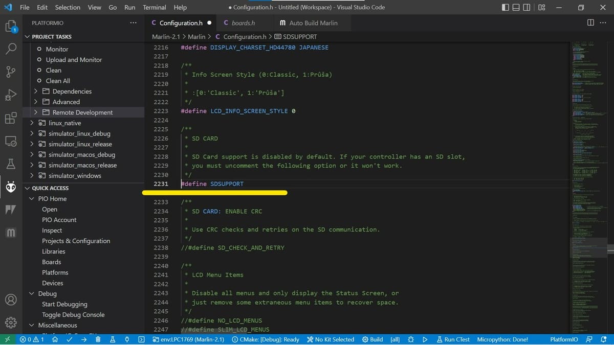
Having an SD card reader and LCD screen makes 3D printing a lot more convenient and also frees up your computer. Scroll down to the LCD and SD support section, which is towards the end of “configuration.h”.
SD card support is disabled by default. To activate it, simply remove the forward slashes:
#define SDSUPPORT
For LCD support, you’ll need to know what type of LCD you’re using. Scroll down to the LCD controller section and search for the type of LCD you have. We’ll assume a “Full Graphic Smart” controller as an example. Once again, remove the slashes:
#define REPRAP_DISCOUNT_FULL_GRAPHIC_SMART_CONTROLLER
You’ll also need to install the u8glib library. To do this, first download the u8glib library from GitHub. Then, Arduino and PlatformIO provide instructions to help you integrate the library into your IDE.
Uploading the Code
As a general guide, we recommend keeping good track of what you’re editing. Do only one or two edits at a time and check if the project compiles. In case of any errors, read the first lines of the error codes to get a clue of what went wrong. Then, rectify the error and try again. If too many edits are made at a time, it can be challenging to track down all the errors. In the worst case scenario, start again from a clean config file.
When you’re satisfied that everything compiles and you’ve done all the changes you want to make, you can upload the compiled binary file. To do this, connect your PC to your controller board with a USB cable or write the .bin file to a SDcard and insert it into your board’s SD card slot.
In PlatformIO, you can compile and upload with the tick symbol followed by the right arrow symbol in the bottom taskbar. Alternatively, you can open the Marlin project in PlatformIO (if edited elsewhere), adjust the build environment, open Marlin Auto Build, and click “Upload”.
In Configuration_adv.h you’ll find the more advanced features and the fun can really begin. Get adventurous and try to improve print quality by using linear advance, for example.
License: The text of "How to Set Up & Edit Marlin Firmware" by All3DP is licensed under a Creative Commons Attribution 4.0 International License.