Klipper: Input Shaping – Simply Explained

Klipper Input Shaping improves print quality by exorcising the ghosts caused by vibrations and resonances. Read on to learn all about it!
Klipper is 3D printer firmware that, instead of processing G-code on a printer’s motherboard, offloads this to a separate computer (usually a Raspberry Pi). Not only does this give Klipper more capacity to perform calculations, but it also allows the printer’s controller to focus all its attention on driving its own hardware.
This allows Klipper, in theory, to print faster and to a higher quality than traditional approaches, as it can crunch through calculations quicker and drive the printer harder. However, speed brings its own issues. For example, parts of the printhead can resonate like the ringing of a bell. Although you may not hear or see this, it can manifest itself in strange reflected patterns on the surface of a print, which reduce print quality. Among makers, this effect is called a variety of names, including ghosting, echoing, rippling, and ringing.
In this article, we’ll take a look at a feature Klipper has deployed to counter ghosting. It’s called “Input Shaping”, and it takes a bit of effort to set up. Let’s check out how it works!

Why Printers Vibrate & Resonate
Before we get into the details of Klipper’s Input Shaping feature, let’s first discuss why 3D printers vibrate. In fact, everything vibrates when subjected to repeated external forces. At certain frequencies objects can “resonate”, meaning that the amplitude of the vibrations becomes particularly intense.
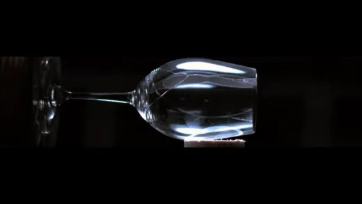
A violin or guitar takes advantage of this to amplify musical notes, a washing machine on the spin cycle may resonate enough to move across a floor, and a “singing” wine glass might do so with enough intensity to shatter.
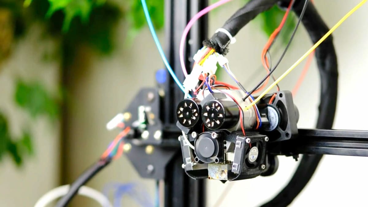
A printer’s printhead isn’t locked solid, and when subject to rapid movements, it too will vibrate and may also have a pronounced resonant frequency where that movement or vibration is most significant. Sometimes, there may be multiple frequencies that are pronounced.
Although this effect may not be directly visible, it results in the nozzle not being exactly where it’s assumed to be. In effect, it’s very slightly in the wrong place as far as the G-code is concerned, and this shows up through artifacts on the print’s surfaces.
This issue has always challenged 3D printer designs, and a lack of structural rigidity or oscillations in drive belts can make matters worse. Large printers and printers with heavy printheads are especially prone to this. As outlined in our article on ghosting, there are mechanical steps that can be taken to reduce the effects, but these aren’t always fully effective.
After addressing mechanical issues, as far as possible, the only other step that can be taken is to reduce print speeds – or at least reduce the accelerations driving the printhead. If reducing speed isn’t an option and if all local mechanical fixes have been tried, this is where Klipper’s Input Shaping has a particular role to play.
What Is It?
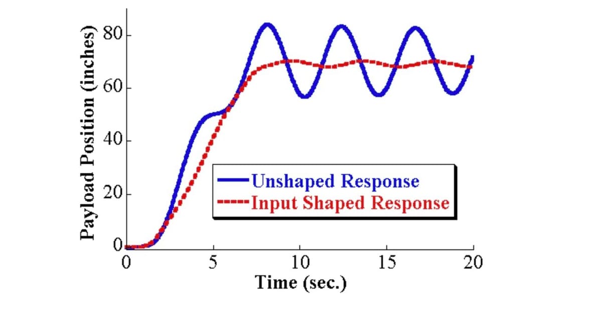
Input Shaping, also known as Resonance Compensation, reduces or eliminates ghosting by canceling out resonances – a bit like noise-canceling headphones, which filter out background sounds. The feature takes a bit of effort to set up, so when is it worth implementing?
Ultimately, this is a judgment call. Ghosting is caused by physical issues with the printer and gets progressively worse as print speed increases. This is especially the case if the printhead or other moving parts are heavy.
A certain amount of ghosting might be acceptable, but if achieving great print quality is a priority or the highest possible printing speeds are required, going through the calibration process is almost certainly worth it. Input Shaping can significantly reduce or entirely remove ghosting – resulting in faster, better prints and also less wear on your printer.
That said, because of how it’s implemented, Input Shaping isn’t guaranteed to 100% eliminate negative effects of vibrations. Let’s take a deeper dive in order to understand why.
How It Works
The concept of Input Shaping is well known in engineering control theory, but implementing it can be mathematically challenging. So kudos to Dmitry Butyugin who cracked how to include it in Klipper.
Input Shaping’s starting point is understanding at what frequencies and how significant resonant vibrations are. (We’ll explore how this is done later.) Armed with this information, a number of mathematical models can be used to precisely compensate for vibration by proactively changing the motion of a printer’s stepper motors, in effect putting the brakes on undesirable movements. If you want a technical explanation, it does this by convolving a sequence of impulses fed to the stepper drivers!
Input Shaping Formula
The various types of Input Shaping models that do the actual compensation have esoteric names such as “MZV” (magnitude zero vibration) and “3Hump-EI” (where “EI” means extra-insensitive)! Thankfully, you don’t need to understand what goes on under the hood, as there are simple-to-follow guides to help determine which is the best fit for the measured results.
The right model will depend on your printer type (e.g. Cartesian, CoreXY, Delta, among others) and a variety of other factors. It’s also likely that the best solution for the X- and Y-axes may be different, too.
Setting Up in Klipper
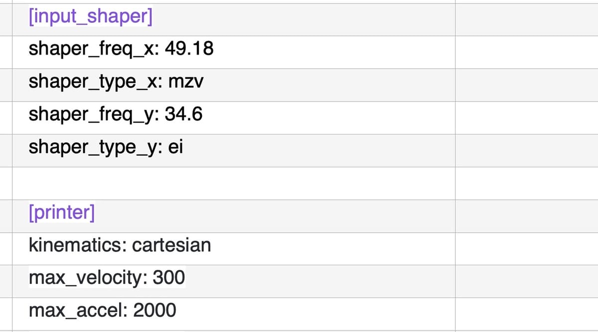
The appropriate Input Shaper types along with the associated resonant frequencies are entered in Klipper’s standard configuration file, which is read every time Klipper starts. For example, the following entry in the configuration file will choose the MZV type at 49.18 Hz for the X-axis and EI type at 34.6 Hz for the Y-axis:
shaper_freq_x: 49.18 shaper_type_x: mzv shaper_freq_y: 34.6 shaper_type_y: ei
If that’s Greek to you, don’t worry. We’ll explain what it all means. At this point, it suffices to know that after a Klipper restart, these changes will take immediate effect and Input Shaping will be enabled. It’s also important to keep in mind that these settings may need to be revisited if any significant physical changes are made to the printer, including changing belt tension.
Configuration Methods
Clearly, we need an appropriate method to identify the resonant frequencies on the X- and Y-axes and select the appropriate Input Shaping type from the several available models. There are two ways to do this. The first is a manual configuration, which involves printing a calibration piece and taking measurements from it. It has the advantage that it’s fairly straightforward to implement, but the disadvantage is that it’s less accurate and struggles to handle more complex resonances.
The other way to do it, an automatic configuration, has an edge when it comes to accuracy but is more involved to implement. In addition to a series of automated test scripts, automatic configuration relies on an accelerometer, which is physically attached to the printhead and, if it has one, also to the printer’s moving bed.
Let’s take a look at these two approaches in more detail.
Manual Configuration: The Preliminaries

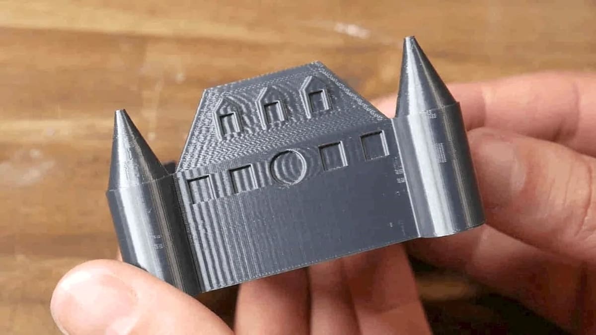
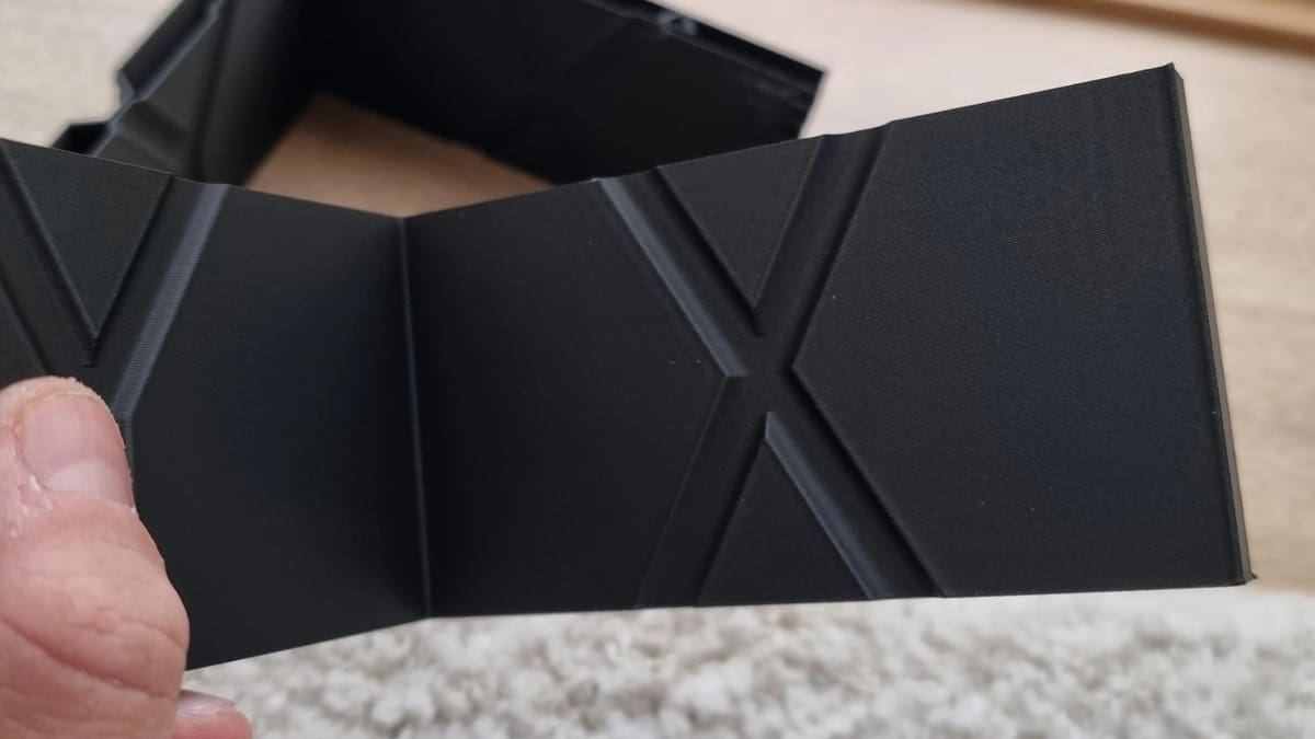
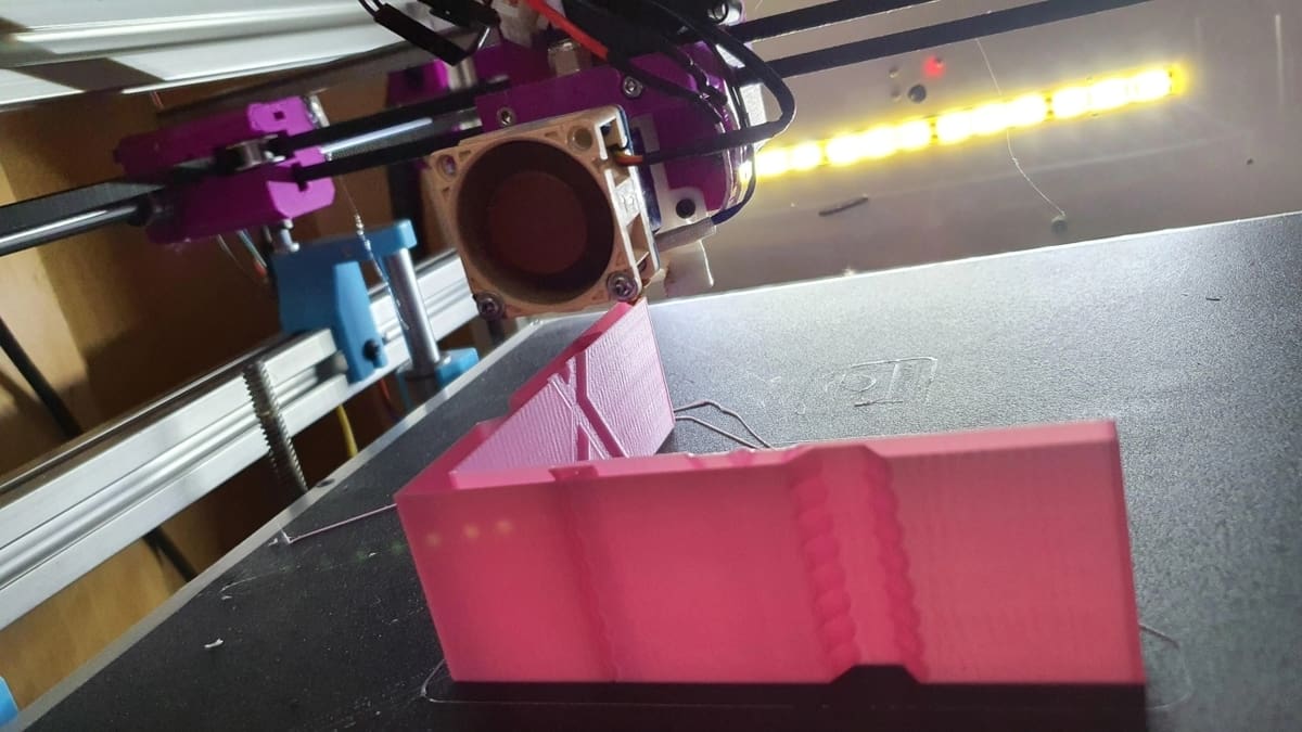
The most common, although less accurate, way to configure Input Shaping is to print a calibration test piece known as a tuning tower (the link automatically downloads the STL file). It comprises two perpendicular walls: one for the X-axis (which is annotated with ‘X’ on the rear) and another for the Y-axis (which is also annotated on the back side of the wall). The walls feature repeating scalloped shapes that are used to make the calibration process easier. They magnify any ghosting in both the X and Y directions.
When it comes to printing the tower, there are no particular material requirements. It’s best, however, to print with your usual filament.
Slicer & Klipper Settings
The tuning tower needs to be sliced in a particular way: a layer height of 0.2 mm or 0.25 mm, a print speed of 80 mm/s to 100 mm/s for external perimeters, a minimum layer time of no more than 3 seconds, with any dynamic acceleration control features disabled.
Klipper itself also needs to be set up in a specific way, with features such as Pressure Advance switched off, Square Corner Velocity set to default values, and importantly, Max Acceleration set to 10,000.
Test Execution
During the process, we’ll print more than one tower, using different settings. Initially, it’s printed using a Klipper command that increments acceleration upwards after each vertical 5 mm of the test print has been completed:
TUNING_TOWER COMMAND=SET_VELOCITY_LIMIT PARAMETER=ACCEL START=1500 STEP_DELTA=500 STEP_HEIGHT=5
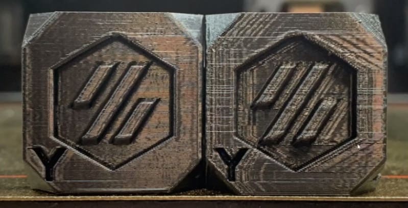
This acceleration will start at 1,500 mm/s2 and increase in additions of 500 right up to 7,500 mm/s2. This may be too much for your printer, so be prepared to stop the test early if necessary. Also, if ringing is already clearly visible (see image below) you don’t necessarily have to run the test print to the end either.
When the tower is printed, it can be visually inspected and measured to provide the first data you need. Let’s take a look at what’s involved with this and also how to set up any resulting Input Shaping configuration.
Manual Configuration: How to Do It
As noted above, the tuning tower is designed to help highlight the ringing frequencies in both the X- and Y-axes, and it’s normal for these to be different. It also acts as a baseline for later comparison and helps to determine whether the natural smoothing applied by Input Shaping is too great.
You’ll use the tuning tower to configure Input Shaping manually, and the process includes identifying ghosting frequencies, selecting the type of Input Shaping, re-printing the tuning tower, then confirming the acceleration values. Here’s how to do it!
Identifying Ghosting Frequencies
Step 1
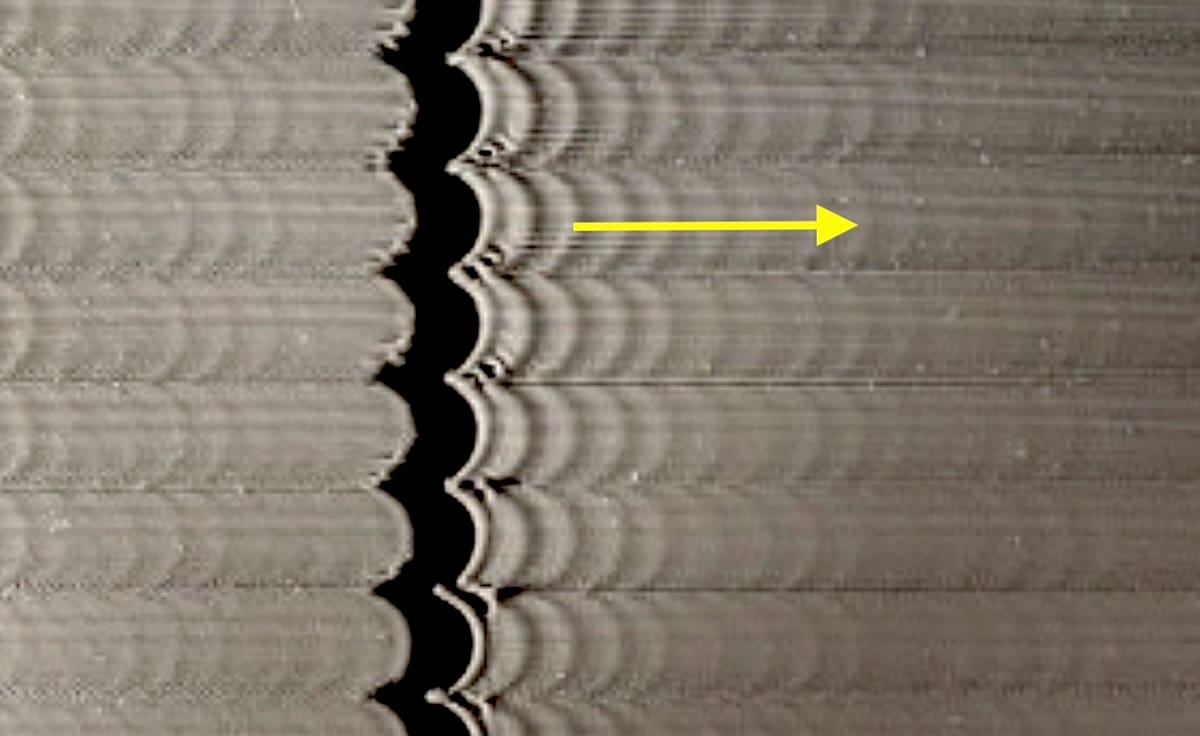
Our first tuning tower allows the predominant ringing or ghosting frequency to be calculated. Start by carefully measuring (in mm) the distance between a given number of repeating oscillations. Choose as many ripples as you can accurately measure with a ruler or caliper.
For example, the yellow arrow in the image above covers six oscillations – normally, the first one or two are ignored. Note that the pattern and process are exactly the same for both X- and Y-axes, but just make sure that you’re reading the correct wall of the tuning tower.
Step 2
The frequency is determined by the print speed multiplied by the number of oscillations divided by the measured distance. In the case of our image above, we’ve identified six oscillations. Let’s assume a 100-mm/s print speed and a 12.2-mm distance. This equates to a frequency of 49.18 Hz.
Step 3
Once identified, the frequency can be entered into the relevant section of the Klipper configuration file. In our example, we calculated the frequency for the X-axis, so the entry would read as follows:
shaper_freq_x: 49.18
The process is then repeated for the Y-axis wall of the tuning tower. Note that if there’s no visible ghosting on one of the axes, it’s okay to simply omit that in the Klipper configuration file.
Selecting the Input Shaping Type
Next, we’ll select what is likely to be the best Input Shaper type and enter this in the config file. The general guidance in Klipper’s documentation is that EI is the best type for printers whose bed moves for the Y-axis (referred to as “bed slinger” printers in Klipper’s documentation) and also for many Delta setups. MVZ is often best for other printer types.
You may wish to check online forums to see what others have selected, but as each printer is different, an element of trial and error may be called for. For our example, let’s use MVZ. We’ll make the following entry:
shaper_freq_x: 49.18 shaper_type: mzv
Also, despite being uppercase in the documentation, the Input Shaper types must be entered as lowercase in the configuration file!
Re-printing the Tuning Tower
You’re almost there now! Restart Klipper and run the same test execution command as before:
TUNING_TOWER COMMAND=SET_VELOCITY_LIMIT PARAMETER=ACCEL START=1500 STEP_DELTA=500 STEP_HEIGHT=5
You should see a marked improvement in ghosting (we’ll explore what to do if not below). For comparison, you can repeat this process with an alternative Input Shaper type.
Confirming Acceleration Values
Next, we’ll determine the acceleration values by examining the second test print. Take a close look at the part of the tuning tower with a small 0.15-mm scalloped gap. Input Shaping introduces a certain amount of smoothing, and this gap is a measure of how much is taking place. The greater the acceleration, the greater the smoothing and the wider the gap.
The point at which the gap widens noticeably beyond 0.15 mm determines the maximum recommended acceleration. Remember that, by default, the tuning tower acceleration starts at 1,500 mm/s2 and increases by 500 mm/s2 after each 5 mm.
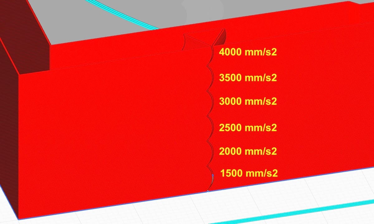
For example, if the gap widens above 20 mm (at which point the acceleration is 3,500 mm/s2), the recommended maximum acceleration would be the lower value of 3,000 mm/s2. Maximum acceleration is defined in the Klipper config file as “max_accel”. So, you’d enter the following in the configuration file:
max_accel: 3000
Note that there are several factors at play here that may require fine-tuning or involve a trade-off between print quality and absolute speed and acceleration. We’ll look at this in more detail in the automatic configuration sections below. But for now, if everything has gone to plan, you’re all set!
Tips
There are cases where you may struggle with interpreting the tuning tower. For example, the distances between ghosted images might not be regular, which could imply that there are multiple resonant frequencies or that something else is wrong. Klipper’s documentation has a section on unreliable measurements, which may help in such cases. However, you may need to look to the more advanced way of establishing resonances using additional hardware, as explained in the following sections.
Also, you may not see a gap at all in your tower when looking to set max acceleration. This can happen with Bowden implementations where you may even get blobs on the scalloped pattern. In this case, you can re-run the above process but with Pressure Advance switched on.
Auto Configuration: The Preliminaries
A more accurate method to set up Input Shaping is to attach an accelerometer to your printer’s printhead. An accelerometer provides a direct and detailed analysis of vibrations to allow faster and better-tuned model selection as well as more insight into acceleration control. Klipper also has an auto-calibration script that will analyze the accelerometer’s results and propose the best solution(s).
Compatible Accelerometers
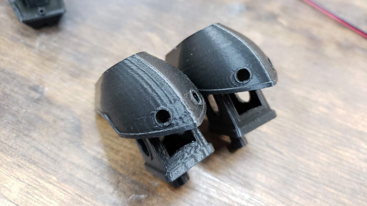
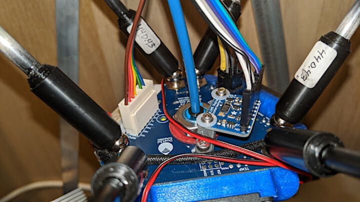
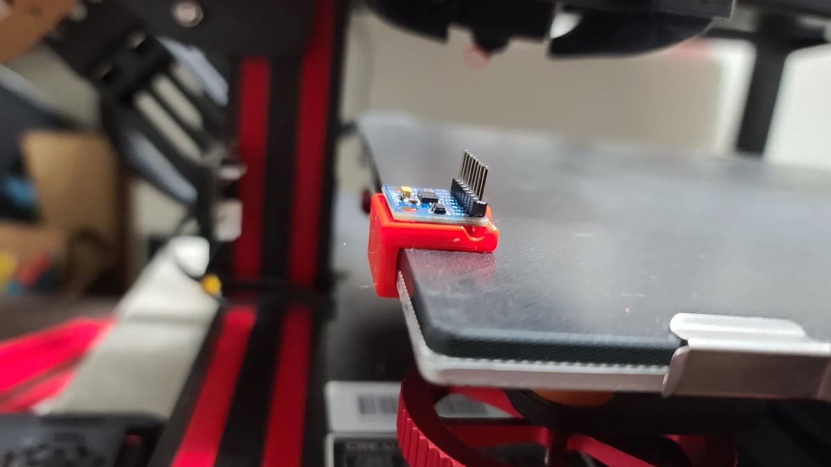
Klipper supports the relatively low-cost and available ADXL345 accelerometer – the 343 will work, too, but has a lower spec – and also the MPU-9250 (or MPU-6050). These need to be firmly attached to the printhead, and STLs are available for various mounting adapters.
Note that printers that move their bed in the Y-axis direction also need to mount an accelerometer on the bed itself. Unfortunately, the majority of low-cost hobbyist printers such as Ender 3s fall into this category. A single accelerometer can be swapped between the printhead and bed for X- and Y-axes tests respectively, or two separate accelerometers can be used.
Setting Up the Accelerometer(s)
The accelerometers connect via an SPI interface, so they can be wired directly to a Raspberry Pi. They can also connect via the printer’s controller, providing it’s fast enough, which may be an advantage in multi-printer setups. If you go the Raspberry Pi route, it will also need a few non-default configuration changes, which are clearly outlined in Klipper’s Resonance Measurement documentation. You’ll also need to specify which accelerometer is being used in Klipper’s configuration file. Again you’ll need to consult the relevant software installation guide.
Note that the SPI connection rules out this approach for Klipper implementations running on devices without such an interface. Also, the detailed Klipper documentation refers to using OctoPrint several times, but any Klipper user interface will work.
Testing the Accelerometer
After installation, it’s worthwhile to test the accelerometer and make sure it’s okay. Again, Klipper has partially automated this. So, you can simply run the following script:
ACCELEROMETER_QUERY
There’s a variant of this for printers that need more than one accelerometer so that separate X and Y tests can be run. The script requires you to define which accelerometer to query. Take a peek at the section “Checking the setup” in Klipper’s documentation for more details.
An additional test, MEASURE_AXES_NOISE, will check for excess noise that may be caused by power supply issues or poor-quality fans interfering directly with the accelerometer. Try switching off fans if this happens.
Auto Configuration: How to Do It
After setting up the accelerometer, we’re ready to do the automatic configuration. We’ll start by grabbing data from the accelerometer(s), analyzing it with a script, then adding the recommended configuration to Klipper’s standard configuration file. Let’s get started!
Running the Calibration Script
If the accelerometer is working correctly, you’re ready to run a calibration script and map the frequencies at which your printer vibrates the most. You’ll do this in turn for each axis, running first the script for one axis, then the other:
TEST_RESONANCES AXIS=X
TEST_RESONANCES AXIS=Y
Be forewarned that this script is designed to shake up the printer and induce vibrations. It’s worth standing by to execute an M112 emergency stop command if any extreme vibrations or other hardware issues occur. If the vibrations are too great early in the test, there’s a configuration option available to fix this: Search for “accel_per_hz” in Klipper’s Measuring the resonances documentation.
After completing these scripts, Klipper will store the results in two CSV files: “/tmp/resonances_x_*.csv” and “/tmp/resonances_y_*.csv”.
Analyzing the Data
The next step is to analyze the data in these files and implement the most appropriate Input Shaping configuration. A little more Klipper magic comes into play here. Run the following calibrate_shaper.py script on your Raspberry Pi as follows for each axis:
~/klipper/scripts/calibrate_shaper.py /tmp/resonances_x_*.csv -o /tmp/shaper_calibrate_x.png

~/klipper/scripts/calibrate_shaper.py /tmp/resonances_y_*.csv -o /tmp/shaper_calibrate_y.png
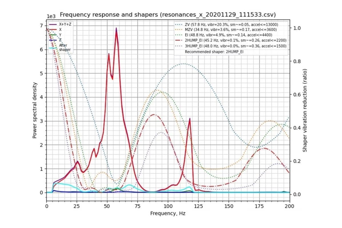
These scripts process the accelerometer results in the CSV files, run simulations to determine how each Input Shaping type might behave, and also create a graphical image of the results (as shown above).
The Results
For each possible model type (ZV, MZV, EI, 2HUMP, and 3HUMP), the script will also report back its findings and summarize them at the top right of the graphical image. You’ll see, for example, something like the following:
Fitted shaper '2hump_ei' frequency = 45.2 Hz (vibrations = 0.1%, smoothing ~= 0.264) To avoid too much smoothing with '2hump_ei', suggested max_accel <= 2200 mm/sec^2.
The script will also make a recommendation for what’s likely to be the best fit. In this example, the summary offers the following:
Recommended shaper is 2hump_ei @ 45.2 Hz.
Multiple Resonant Frequencies
It’s also worth mentioning that this example highlights a key benefit of using an accelerometer. There are two resonant frequency peaks, around 55 Hz and 120 Hz, and this is extremely difficult to determine using manual methods.
The “2HUMP” model type works well in cases where there are two resonant frequencies, but note that only a single frequency needs to be defined to set it up, as per Klipper’s recommendation. This is typical of the way Input Shaping is implemented; the model needs only a single target frequency to reduce the net impact of all that are detected.
By the way, the typical cause for more than one resonant frequency is either a loose physical component or unequal CoreXY tensions. This brings up the standard suggestion whenever doing any sort of 3D printer fine-tuning: Always make sure your printer is properly set up, configured, and calibrated!
Setting Up the Configuration File
From this point onwards, the process is similar to the manual configuration.
Step 1
In the Klipper configuration file, set the appropriate X and Y frequencies, as well as the selected model types. The values will be taken directly from the output of the script.
In the example above (assuming the results are for the X-axis), the configuration file would be as follows:
 shaper_freq_x: 45.2 shaper_type_x: 2hump_ei

 max_accel: 2200
Step 2
Restart Klipper, and Input Shaping will be enabled.
Tuning the Results
In most cases, this will result in a marked printing improvement. You can print the tuning tower used for manual calibration to confirm the improvement. However, as with manual configuration, there’s still scope for judgment and fine-tuning.
In particular, you may have noticed that the script above also flags a smoothing parameter: (vibrations = 0.1%, smoothing ~= 0.264). This is an indicator of how much smoothing the shaper type is applying and that too can be modified in the Klipper configuration file as follows:
max_smoothing: 0.25 # an example
Lower smoothing can allow higher accelerations to be set, but a few factors come into play, such as Pressure Advance, the Max Smoothing setting, and Square Corner Velocity. It’s worth reviewing the “Max smoothing” section of Klipper’s documentation if you’re interested in exploring more.
Final Thoughts
Klipper’s Input Shaping feature is well implemented and supported by many case examples and glowing reviews. If you want the best print quality at high printing speeds – especially with larger printers – it has a clear role to play and is worth the effort to configure. The choice between manual and automatic configuration is the question most prospective users wrestle with.
Manual configuration has the advantage of not needing additional hardware – especially in the case of printers with a moving bed – and is reasonably straightforward to implement. It has the disadvantage of being less accurate, and it also struggles to handle atypical situations – for example, cases with more than one resonant frequency.
Automatic configuration has a significant edge when it comes to accuracy. The installation of extra hardware may seem daunting, but helpfully, there are many printer-specific examples discussing in online forums.
As was alluded to earlier, the accelerometer can be used for other purposes relating to tuning acceleration or testing physical modifications. For example, it can also be used to help calibrate belt tensioning in CoreXY machines. (See eddietheengineer’s YouTube video.) Poor calibration is often the cause of more than one resonant frequency and should ideally be addressed before implementing Input Shaping.
Both the manual and automatic approaches leave scope to further tune acceleration, smoothing, and other related parameters, but in general, this isn’t required. The consensus view, by those who have tried both, is that if you’re comfortable with the extra work and (the not too significant) additional expense, the auto-approach is worth implementing, but both will deliver clear benefits.
Happy shaping!
License: The text of "Klipper: Input Shaping – Simply Explained" by All3DP is licensed under a Creative Commons Attribution 4.0 International License.