How to Calibrate Your 3D Printer: A Step-By-Step Guide

Check out our 3D printer calibration guide to learn how to calibrate your 3D printer and fine-tune your slicer settings!
So you’ve had your 3D printer for some time now. You’ve leveled the bed and fiddled with your slicer settings, but now you want to go the extra mile. It’s time to get into the G-code and tweak the very code that tells your motors how to move.
Calibrating your 3D printer ensures that every print will turn out the same, every time. While you may need to invest a little time fine-tuning the first layer, stepper motors, and filament settings, it’s sure to pay off in terms of print quality. With just a few adjustments, you can optimize your printer’s abilities.
In this article, we will dive into the code and calibrate our settings to get ever more perfect prints. Should you come across any challenges on your 3D printing journey, you might want to also give our troubleshooting guide a look.
But for now, let’s get started!
Dialing in the First Layer
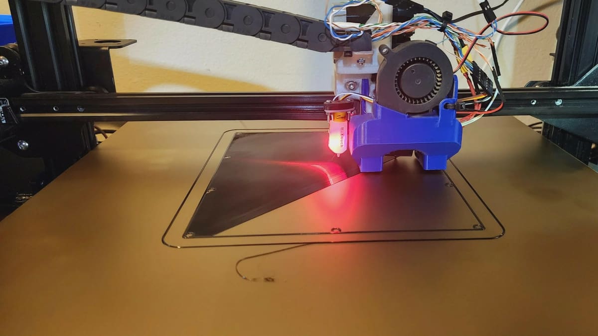
As the foundation, a good first layer is crucial to achieving a beautiful print. If your nozzle is too close to the bed, your first layer will be squished and possibly destroyed, meaning you’ll have to scrap it. On the other hand, if your nozzle is too far away from the bed, your print will lack adhesion and likely fail.
You can improve your first layer by tuning the Z offset. This is a value that essentially tells your printer how far to move the Z-axis from the Z endstops – in other words, from the bed.
The goal, in a nutshell, is for your first layer to stick perfectly to the bed. If you see that your first layer is squished or the nozzle is digging into it, you should increase the Z offset. On the other hand, if your first layer is peeling up from the bed, you’ll want to lower the Z offset.
Before making any changes to your Z offset, though, you’ll want to thoroughly clean your print surface using isopropyl alcohol (depending on the bed’s material) to remove any dust, debris, or oils left on the print surface from past part removal. This will make absolutely certain that you are dealing with a Z offset issue and not a print adhesion issue when calibrating.

Calibrating the Stepper Motors
3D printers use stepper motors, which rotate in small steps in order to move axes or the extruder a certain distance. For example, if one rotation is 100 steps, then the motor must rotate 50 steps to turn half of a rotation. This allows for precise rotation control.
For a 3D printer, calibrating your stepper motors involves determining the relationships between steps and distance. To calibrate the extruder, you’ll need to make sure that your 3D printer is extruding the right amount. To do this, you’ll have to send a few G-code commands to your printer.
Before calibrating your stepper motors, though, you will want to check the belts. A loose belt can and will cause inconsistencies in your prints and throw off any attempts at calibration. Most 3D printers will have belts along the X- and Y-axes. Make sure that they are properly tightened before moving on.
When it comes to G-code commands, Pronterface is a good option that allows you to send G-code directly from your PC to your 3D printer, usually over a wired USB connection; there are alternatives, as well. You can learn more about them, as well as the basics of G-code, in our guide on 3D printer G-code commands.
Step 1: Prepare Your Values
In this step, we’ll compare your printer’s settings with how it actually prints. If there’s a discrepancy, we’ll do a few calculations to correct it.
- First, retrieve your printer’s settings by sending the command
M503. Part of the output should look like the following:Steps per unit: M92 X100.00 Y100.00 Z400.00 E140.00 - Take note of these values. The first three correspond to the number of steps that the stepper motors take to move one millimeter in the X, Y, and Z directions, respectively. We aren’t concerned with those at the moment, but we’ll need them later. Right now, we care about the last value, which is the number of steps that the extruder motor takes per millimeter of extruded filament. We’ll call this number A.
- Next, insert some filament and make a mark about 50 mm above the top of the extruder. Measure the exact value with calipers and write it down. Let’s call this number B.
- Next, extrude 10 mm of filament and again measure the distance from the top of the extruder to the marked point. If we call this value C, then B – C is the amount of filament that was extruded.
Number Crunching
If B – C = 10 mm, then the extruder is already calibrated correctly! If not, we need to update the extruder’s steps per millimeter.
Compute the value D = 10*A / (B – C). This is the new number of steps per millimeter for the extruder. For best results, it may help to repeat the process for measuring D multiple times, and then take the average. This will also help to offset small measurement errors.
Step 2: Calibrate Your 3D Printer Extruder
To carry out the calibration, you need to tell the printer the new value:
- Send the command
M92 E[D]to the printer. While this command tells the printer the new value, it does not actually save it. - Send the command
M500to save the new value.
Now, the extruder should be calibrated correctly.
Example
Let’s suppose that before our test extrusion, we measured the distance between the marked point and the top of the extrusion to be 53.10 mm, and after the test extrusion, we measured the distance to be 42.80 mm. Then B – C = 10.30 mm.
If the original number of steps per millimeter for the extruder was 140, then we would calculate 10*140 / 10.30 = 135.92, and send the command M92 E135.92.
Tips
In this case (and later, when you calibrate the axes), do not expect your results to be perfect. There’s bound to be variation after you confirm that your calibration is correct, but as long as you are pretty close (within a few percent) to the desired value, your printer should be well-calibrated.
Step 3: Calibrate Your 3D Printer Axes
After calibrating the extruder, it’s also important to calibrate the axes of the printer. Calibrating the axes is similar to calibrating the extruder, but requires that you actually print something.
Please keep in mind that calibrating the extruder should always be done before the axes because the former can affect the size of printed objects. As the axes calibration involves measuring prints, you want to make sure the extruder is adjusted beforehand.
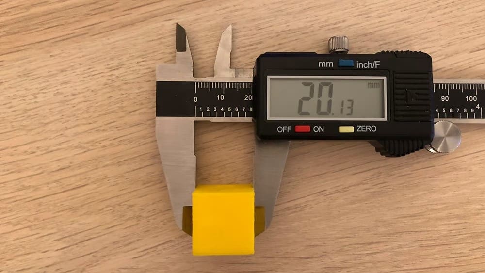
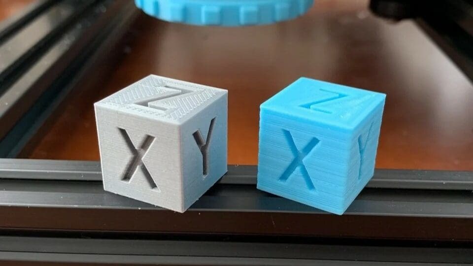
For the axes calibration, you can print a small cube, for example. Either design one yourself in the CAD software of your choice, such as OpenSCAD, or check out the models in The Best 3D Printer Calibration Cubes.
How to Do It
After the cube has finished printing, measure each dimension. For each axis, repeat the computation you did for the extruder, D = 10*A / (B – C), but replace the variables as follows:
- (B – C) with your measurement
- The number 10 with the target value of that measurement
- A with the M92 value for that axis (i.e. the values you noted in Step 1 after sending the command
M503)
Then, send the appropriate M92 commands to the printer, again replacing E with the letter corresponding to the axis you need to set.
Example
Suppose our cube is supposed to be 20 mm on each side, but we measure 20.30 mm in the X-direction. If our M92 value for X was set to 100.00, then we would update this value by sending our printer the command M92 X98.52 because 20*100 / 20.30 = 98.52.
Tips
As with the extruder, it helps to make multiple measurements and take their average. In this case, however, you don’t need to print multiple objects. You can simply measure the cube at different positions (along the same axis).
Fine-Tuning Filament Settings
Every roll of filament is different. Plastics from different manufacturers, and even different colors of the same material, have different properties.
In order to get the best prints possible, you’ll need to fine-tune your filament settings. Usually, you can get good prints just by using the settings recommended by the manufacturer.
For best results, however, in addition to ensuring that the material is dry, you should follow these steps every time you open a new roll of filament.
Step 1: Measure Your Filament
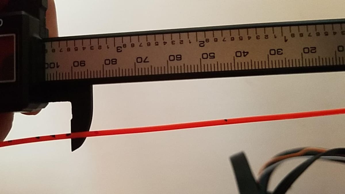
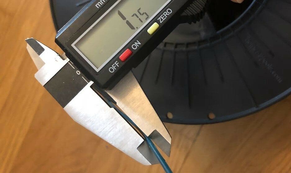
The diameter of a roll of filament often differs from the diameter reported by the manufacturer by up to a few percent. The tolerance in diameter is usually printed on the spool. So, it’s important to use calipers to measure the true diameter of the filament:
- Measure your filament at a few (at least three) places along the spool.
- Take the average of your measurements.
- Enter this result as the filament diameter in your slicer.
Getting this number right is important because it helps to ensure that your printer will extrude the right amount of filament.
Step 2: Find the Right Print Temperature
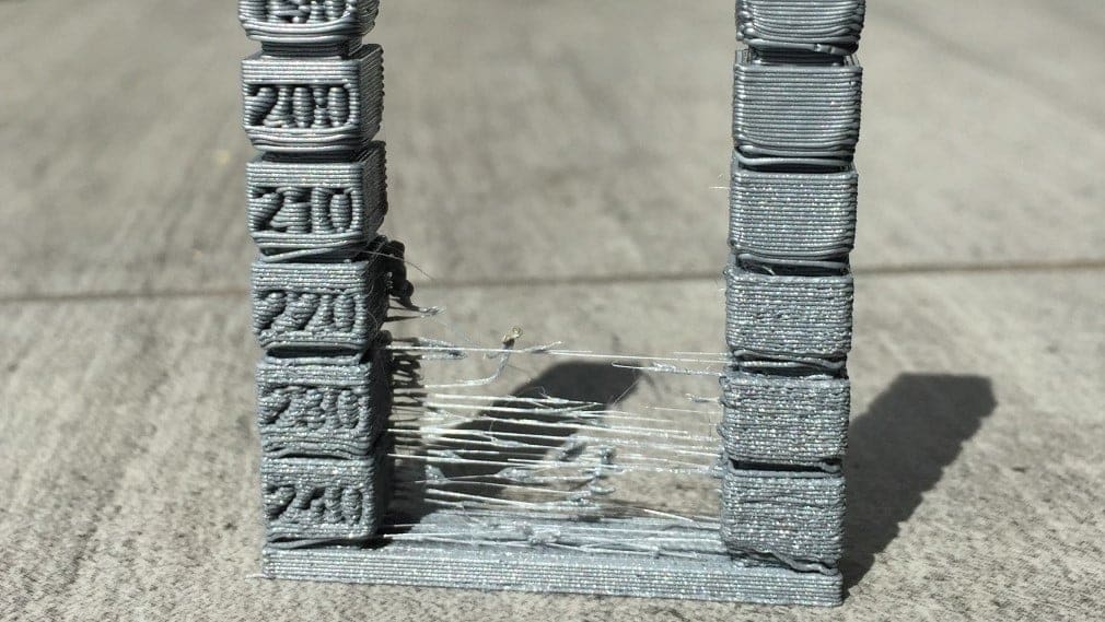
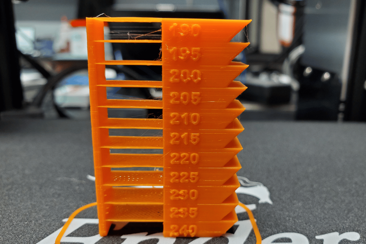
You can find the right temperature to print by printing a “temperature tower“. There are many different options available online, but the basic idea is the same for all of them. They’re separated into blocks at different heights, and each block should be printed at a different temperature. By analyzing the blocks after printing, you can determine the best temperature to print your material.
Most modern slicers allow you to make changes to your G-code directly in the program itself (there are always exceptions, though). We’ll look at two methods on how to find the right temperature. First, we’ll assume your slicer program allows for changes to the G-code. After it, we’ll go over a more hands-on approach, where we’ll change the G-code ourselves.
We’ll be going over the procedures in UltiMaker Cura (version 5.3) and go through the process of testing different nozzle temperatures on the same print. Other slicers will more than likely have a very similar setup, although names or paths might be slightly different.
Method 1
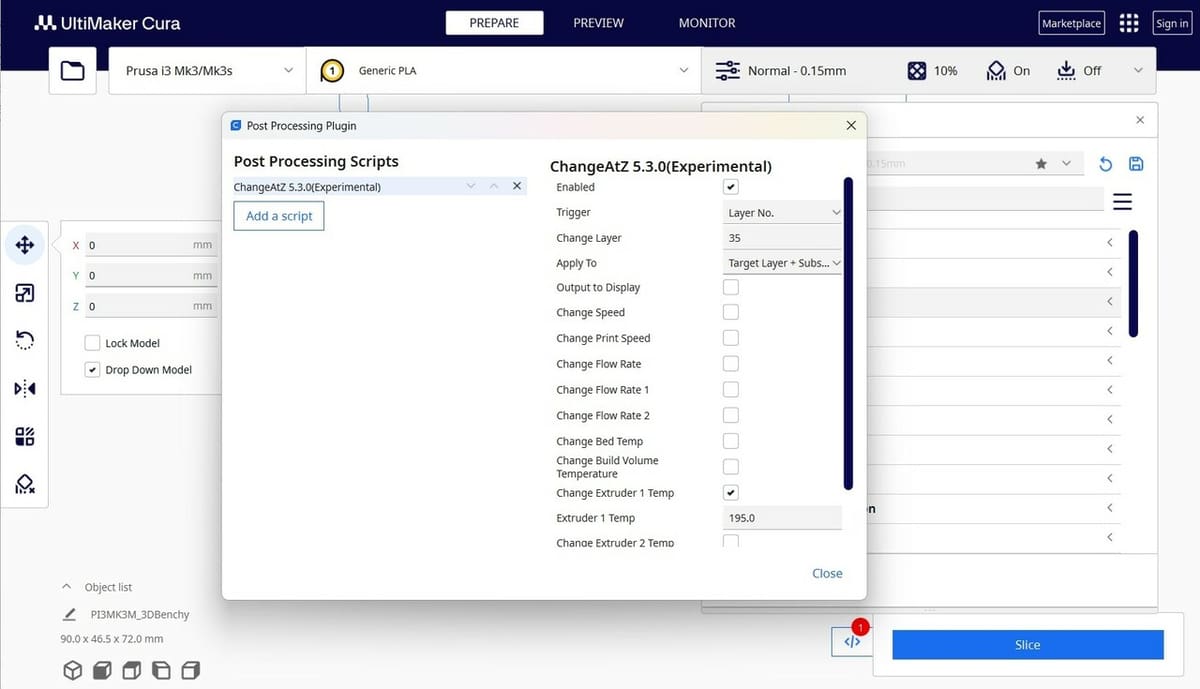
- First, slice your temperature tower and find out what layer heights you need to change your nozzle temperatures. For our example, we will be changing the nozzle temperature every 35 layers.
- From the top toolbar, click on “Extensions > Post Processing > Modify G-Code”.
- Click “Add a script” and select “ChangeAtZ 5.3.0(Experimental)”.
- Change the “Trigger” to “Layer No.” and input the layer of your first temperature change (layer 35 in our example).
- Check the box next to Change Extruder 1 Temp and input the desired temperature change (depending on the tower or test you want to make, this could be a difference of 5 degrees).
- Repeat this process, adding a new script for every change in temperature you want on your model. You can always slice your model and scroll through the layer height view to find the next temperature change layer height for your test model.
- Once you have all of your temperature changes set up, send the file over to your printer and begin printing your tower!
Method 2
- First, determine the height of each block. Call this number H, so that the different blocks start at height 0, H, 2H, 3H, and so on.
- Then, open your G-code file in the editor of your choice. You want to look for commands that tell your printer how to move, which begin with
G1. Your G-code file will contain an enormous number of these. - Find the first G-code command of the form
G1 Z[H]. (It may also contain X and Y movements.) - Before this line, insert the line
M104 S[T]where T is the temperature of the block that begins at height H. - Repeat this for each block, with the appropriate temperature.
- Once you’re done, print the updated G-code file.
Example
If the blocks have heights of 1 cm (10 mm), and the temperatures go from 185 °C to 220 °C in increments of 5 °C, then you should find the first command containing G1 Z10 (the first command that brings the hot end to a height of 10 mm). Immediately before this line, you should set the hot end to 190 °C by inserting the line M104 S190.
Final Steps
Once you’ve printed a temperature tower, examining the different blocks will allow you to determine the best temperature for printing your material. Simply pick the temperature that looks the best. Set this as the printing temperature in your slicer, and you’re ready to go!
Auto-Calibrating Printers
As 3D printers continue to evolve, with new technology and advancements being introduced, more and more of these time-consuming processes are being handled directly by the machines themselves. This has made 3D printing a much more beginner-friendly hobby, as new makers are able to pick up devices that are less of a tinkerer’s toy and more of an appliance.
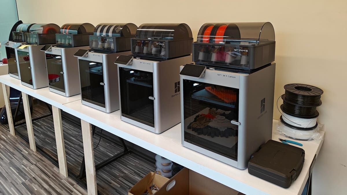
One of the first 3D printers to make an appearance in this appliance-like category was the Bambu Lab X1. Automatic bed leveling has already become a popular feature among the community, however, many makers were still having to make lengthy calibrations to their printers to get decent prints.
The X1, along with the rest of Bambu Lab’s lineup of P1 (P1P and P1S) and A1 3D printers, comes with a slew of sensors that automatically calibrate everything, from Z offset and filament feed rate to per-material settings and even vibration compensation to reduce print noise. This essentially creates a plug-and-play 3D printing experience. While some of these advancements can be attributed to the smart hardware of the Bambu Lab printers, it wouldn’t have been possible without the rapidly evolving Klipper firmware.
Klipper is powerful firmware that allows for more precise computations to be made, resulting in better-quality prints and faster print speeds. While Bambu Lab bases all of their 3D printers on a Klipper-variant, there are plenty of 3D printers that use the open-source firmware, along with smart sensors, to give you a similar experience. Creality’s K1C and Qidi Tech’s Q1 Pro are both great examples of 3D printers that require little to no user input when calibrating, with automatic belt tensioning, pressure (or linear) advance, and input shaping present.
If you aren’t fond of the idea of manually calibrating your 3D printer, you’ll have a much more enjoyable time with one of these choices.
A Little More Torture
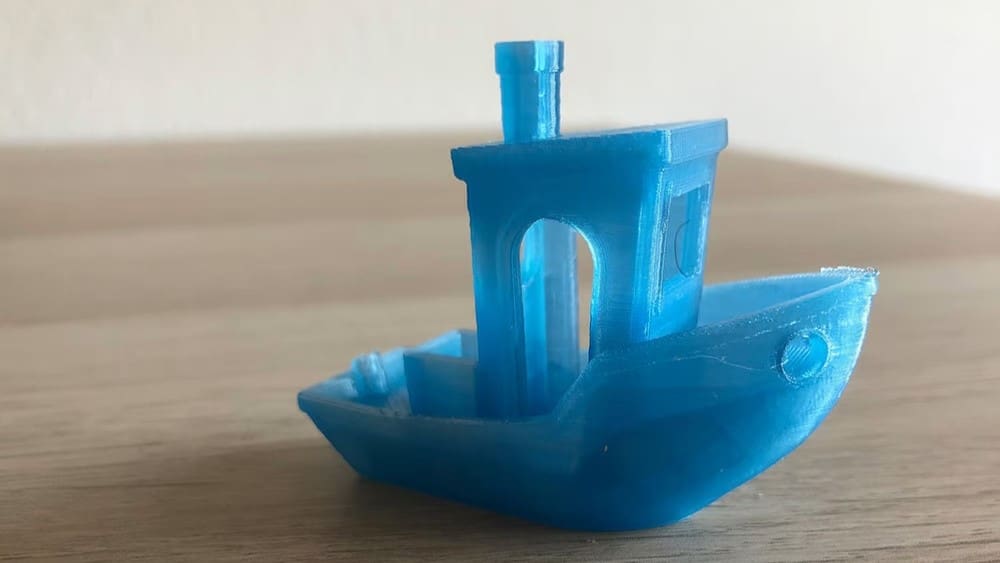
We’ve described the top ways to calibrate your printer’s settings and some slicer settings for your filament. However, there are also plenty of other settings you can change to improve your prints. In order to get an overview of what a printer is good and not so good at doing, people often use “torture tests”. Printing and perfecting such prints can help with problematic areas, such as bridges and overhangs. They’re also helpful for diagnosing a variety of problems.
While the most popular torture test is the 3DBenchy (usually just called a “Benchy”), you can find plenty of others by searching for tests on your favorite STL site. We won’t go into detail here because every torture test is a little different, but most come with instructions on how to diagnose problems and points of failure.

License: The text of "How to Calibrate Your 3D Printer: A Step-By-Step Guide" by All3DP is licensed under a Creative Commons Attribution 4.0 International License.