Gaps in 3D Prints Are A-Void-Able: 7 Types Detailed and How to Fix Them

Gaps in 3D prints are annoying defects that mess up how parts look and work. Check out this guide for easy fixes and how to avoid them!
3D printing is a skill that requires effort and a significant amount of practice to master. Still, there’s nothing more frustrating than having your 3D prints fail constantly. After all, we just want to produce great quality prints that look good and function as they should.
If you’re experiencing gaps or holes in your 3D prints, it can be a tough problem to fix, especially since several different factors can be causing them. In this article, we’ll go over the possible defects that appear as gaps, their potential causes, and how you can deal with them.

First Layer Gaps
The first layer is considered the most important of all, as it provides the foundation for an entire model. Therefore, it can be the deciding factor between a successful or failed print. There are a handful of anomalies that can lead to gaps in the first layer, and all of them may cause more issues than simply aesthetic defects.
Gaps Between Lines
The Problem
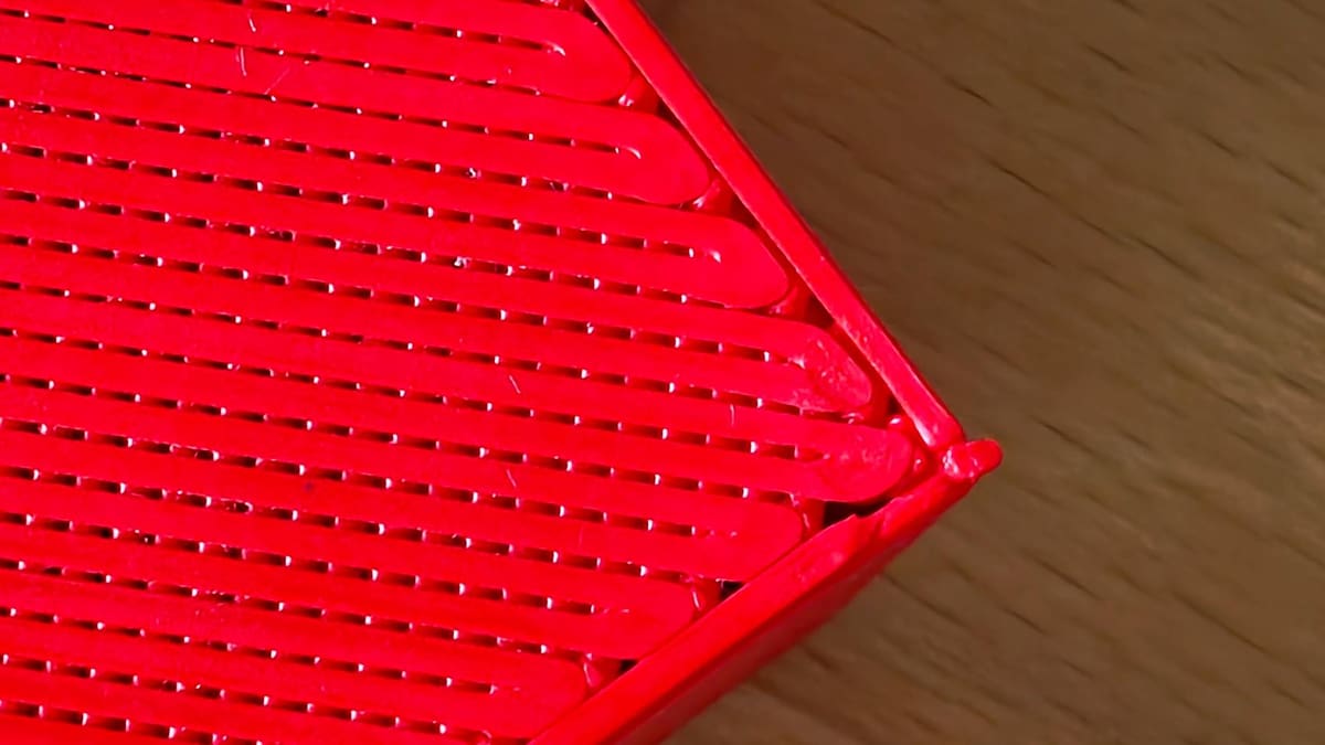
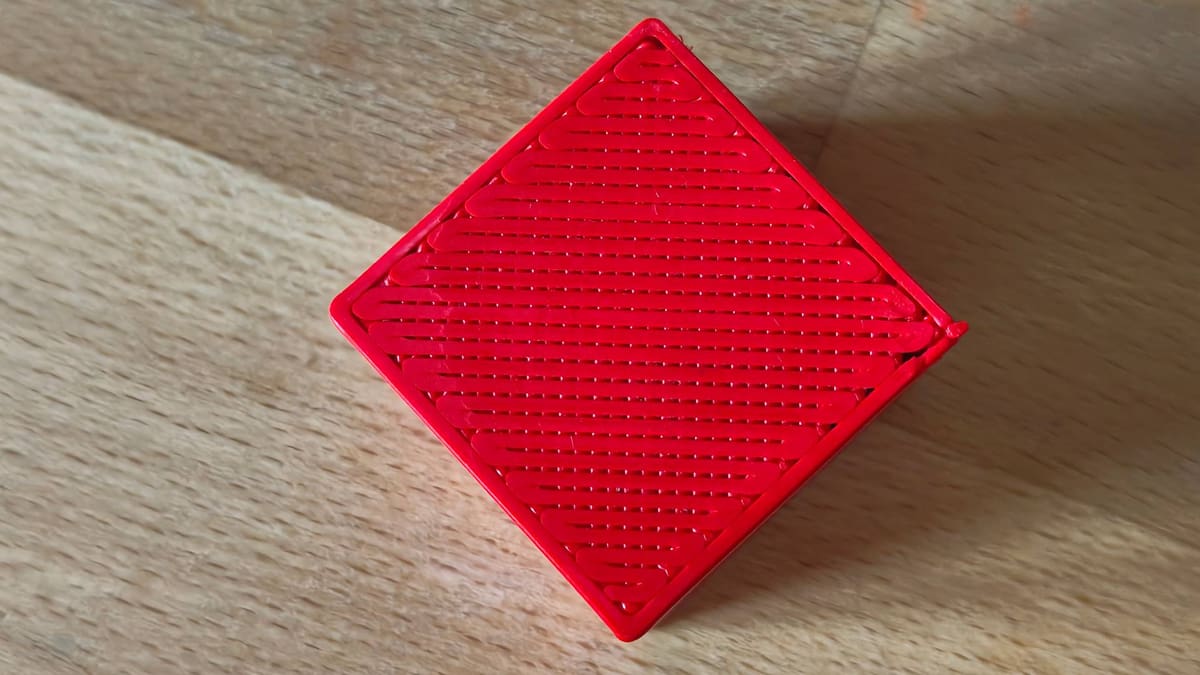
Your print has recurring gaps between extrusion lines in the first layer. The lines seem to be evenly spaced out from one another, creating a grill-like pattern rather than a solid flat surface on the bottom of the print.
Potential Causes
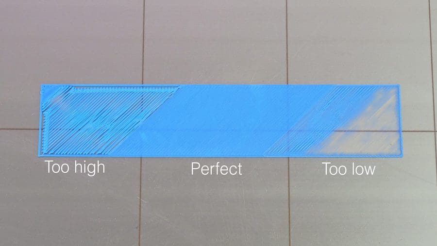
One potential factor is that your Z offset is too large. The Z offset adjusts the physical distance between the nozzle and the build plate. In this case, the nozzle seems to be too far from the bed, preventing the layer lines from being slightly squished during extrusion, which – with an adequate Z offset – would fill in the surface. Under-extrusion might also be the cause, as each line won’t turn out as thick as expected, leading to the pesky gaps between lines.
Areas with Missing Material
The Problem
There are regions of the print’s first layer without material, even though that area has been traced by the nozzle. This is most noticeable while the first layer is printing. Depending on the severity, it could potentially harm the entire print, as part adhesion would become compromised.
Potential Causes
Essentially, the gap between the nozzle and bed is too narrow, preventing material from being extruded. In extreme cases, the nozzle will literally scrape the build surface, potentially leading to clogging or even hardware damage.
A poorly leveled bed or inadequate Z-offset calibration are the most probable causes. Small bumps or warps in the build plate or leftover debris could also lead to minor gaps in the first layer, as can mechanical play in the hardware, such as the screws holding a print head to its rail not being tight enough.
Hole-like Anomalies
The Problem
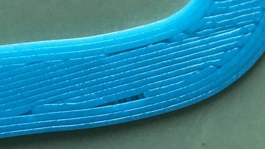
Your print has small spotted gaps in the first layer that look like holes or short line segments. They could appear on entire surfaces or single islands. While they can sometimes be the result of defects in the printing, more likely they’re just a simple reality of the physics of 3D printing.
Potential Causes
Poor bed adhesion can prevent extrusion lines from attaching to the build plate, especially at the beginning or very end of extruding a segment. Extrusion-related issues (like under- or over-extrusion) could also cause these gaps to form in the first layer. But what you’ll most commonly see is gaps left by your slicing software. A fixed extrusion width, particularly on curved parts of your model, cannot fill every tiny gap perfectly. This means you are left with small wedges of empty space where your slicer’s pathing has determined, under the settings you have applied, that the printer can not physically extrude there.
Solutions: First Layer Gaps
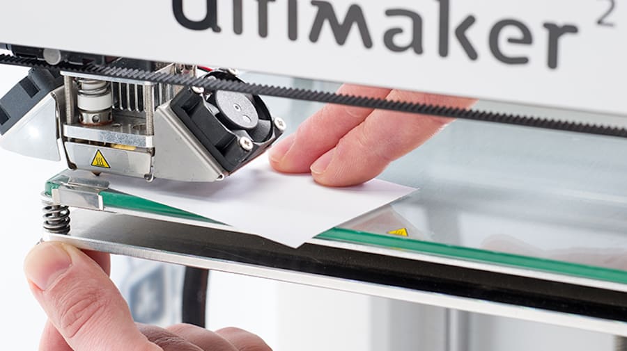
Most of the issues mentioned above can be dealt with by proper print bed calibration. For gaps between lines and areas missing material, Z-offset adjustments should do the trick – these days, this is effectively applied by running your printer’s auto-bed leveling routine, so try that first. If you’ve been running your printer for a while without any maintenance, consider lubricating the Z-axis’ leadscrews to ensure they can move smoothly and as intended.
Likewise, if you’re experiencing inconsistent first layers, consider giving the printer s once-over for loose screws around the motion system, eliminating any looseness you can find. Be wary of eccentric nuts, often seen with printers that use V-slot wheels running along aluminum extrusions for the bed and printhead. Things should move smoothly with no wobble or play – adjusting the eccentrics should tighten things up.
Precise extrusion calibration will guarantee that the right amount of material is deposited, leading to a well-built first layer. Check out your slicer’s flow rate calibration routine to better dial in a material’s flow rate if you suspect it of under extrusion and being the cause of gaps in your layers. If your slicer doesn’t have one, OrcaSlicer’s guide, from which many other slicer’s flow rate calibrations stem, shows you how.
Make sure to always keep your bed clean and level. Also, use proper bed adhesion techniques for materials with high thermal expansion, such as ABS and nylon.
When dealing with tidy gaps left near corners and curves in your print, consider the slicer settings that tell your printer to behave slightly differently around wall widths and features.
Look for the “detect thin walls” setting, which instructs your slicer to intelligently collapse thinner walls comprising more than one shell into fewer, improving the slicer’s ability to calculate fine wall detail where needed. Better still, if the slicer you are using lets you toggle the “perimeter generator” to “Arachne” that achieves the same effect as well as variability in wall extrusion thicknesses.
Gaps Between Layers
As we all know, 3D printing works by adding thin layers of material, one on top of the other, until a three-dimensional object is created. Each layer must be adequately deposited on top of the previous one to create robust and nice-looking parts.
Most gaps between layers are caused by issues with perimeter extrusion or poor layer adhesion, as we’ll see next. Still, there are a few other defects that could be considered gaps, and for this reason, we’ll be covering them, too.
Holes & Pockmarks
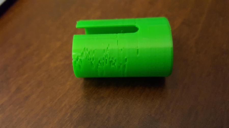
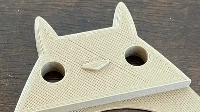
The Problem
Defects appear on the side surfaces of 3D printed models. These are not so much gaps as they are small holes and failed print spots that result in a poor surface finish. They can be either isolated spots or consistent blemishes across the surfaces of the part.
Potential Causes
Mainly, these are the result of extrusion issues, where the plastic isn’t deposited as it should be. Inappropriate retraction settings can also be the cause, as they may hinder the start of extrusion after a move. Moisture in filament can lead to small pockmarks on the surfaces as trapped moisture in the filament rapidly evaporates – this is usually accompanies by a faint “popping” sound as the material extrudes, making it an easy issue to identify.
This can also manifest in prints from the seam settings you use. Randomly placed start and end points of a layer will result in a spread of pock marks in your print, which some filaments showing this worse than others.
Layer Separation
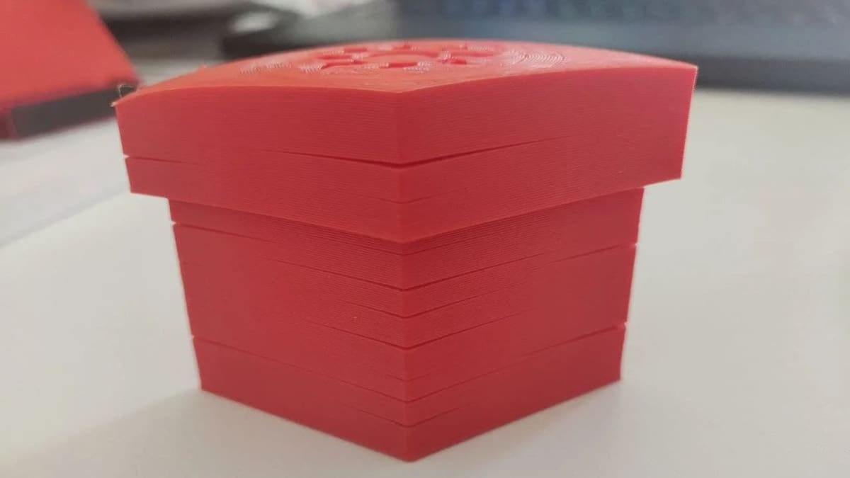
The Problem
Two or more layers are partially split or separated. This phenomenon is also known as delamination, and is more commonly seen in prints using materials that require higher printing temperatures, bed temperatures, and often heated enclosures in order to be printed successfully.
Potential Causes
Low bonding strength between layers is usually associated with low nozzle temperatures, under-extrusion, high-speed printing, or sometimes layer heights that are too large. Materials with high thermal expansion (and contraction) compound the problem, pulling weakly bonded layers apart.
Solutions: Gaps Between Layers
First things first, be sure your filament has been properly stored and is in good, dry printing condition. Following that, question whether you really need the seam placement to be random. If these are the causes for this kind of gap in your print, what follows won’t help much, so check them first.
If you really must have random seam placement, then you can mitigate severe marks from the layer changes by focusing no the 3D printer’s extrusion calibration and retraction settings.
Now, layer separation happens for many reasons. To solve the problem, try to adjust the nozzle temperature and cooling settings to optimal values. Reducing printing speed should also help with layer bonding, along with proper extrusion settings.
For materials like ABS and nylon, a printer enclosure is a great addition, as it can help eliminate warping and aggressive contraction.
Top Layer Gaps
Top layers are the last to be printed, closing up the model and its partially hollow interior. For this reason, they’re printed completely solid – or at least they should be. Gaps on top layer surfaces are quite a common issue, which has multiple causes, as we’ll see in this section.
Gaps Between Lines
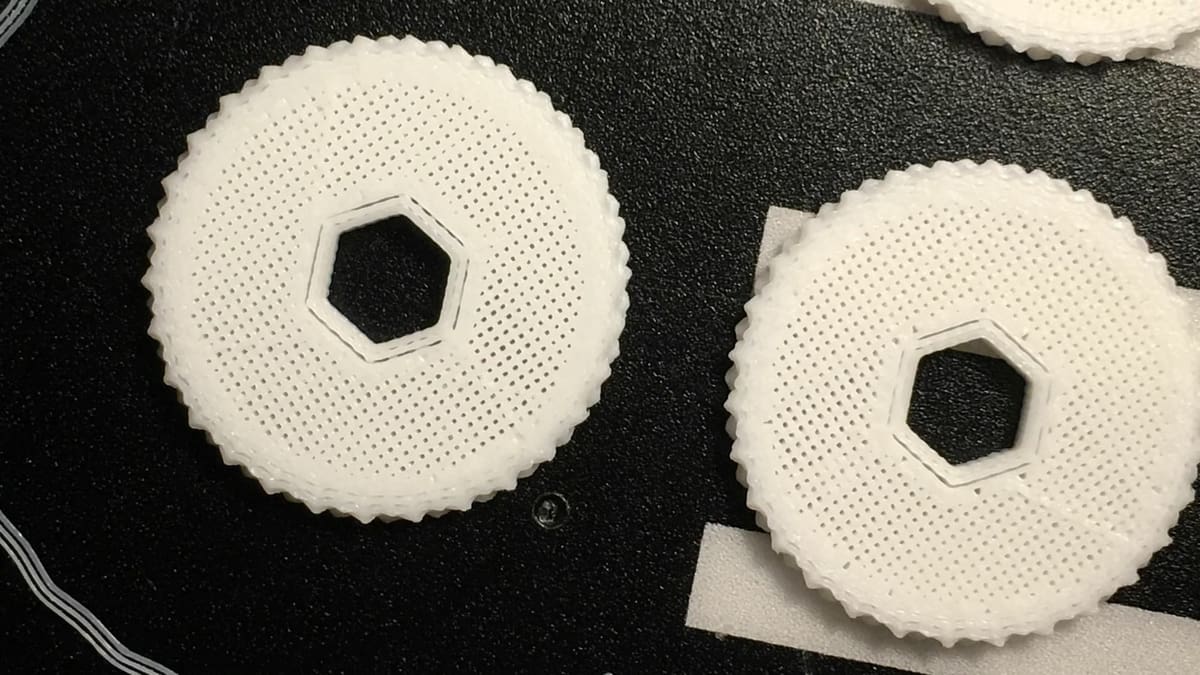
The Problem
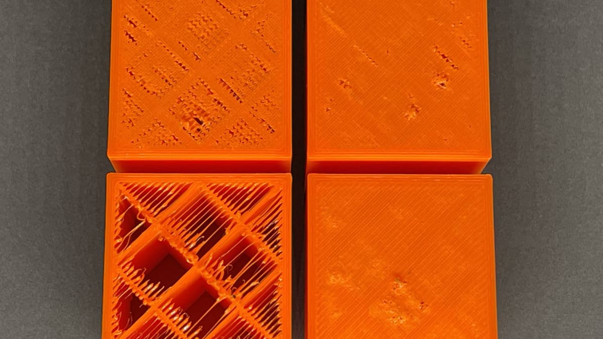
There are consistent gaps between layer lines, leading to flimsy solid top layers that aren’t truly solid. This issue usually affects the entire layer, especially regions printed over the part’s bulk infill.
Potential Causes
Either not enough material is being deposited, or the foundation for that layer isn’t solid enough. It’s also possible that both issues are at play. Therefore, an insufficient number of solid top layers, under-extrusion, and too sparse of an infill could all potentially lead to this situation.
Wall Gaps
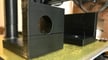
The Problem
A print has holes between the top layer and its perimeter. This is also known as wall separation, and given that the infill is laid in straight lines, it’s easily noticeable in round features such as holes and cylinders.
Potential Causes
Printing the top layer too fast can lead to this issue, as well as severe under-extrusion. In some cases, previous layers printed with too low of an infill percentage can also cause wall gapping.
Solutions: Top Layer Gaps
Besides proper extrusion calibration, increasing the number of solid top layers or the infill percentage could eliminate gaps between lines in the top layers. In order to improve the top layers’ foundation, it’s also worth trying out different infill patterns.
Wall gapping can be extremely challenging to fix. Some 3D slicers like Cura have specific printing settings to correct this issue. A good place to start would be the “Infill Overlap” (Cura) setting, which controls how much the infill overlaps with the outline perimeters. Increasing this value from 15% (usually the default) to 30% can be useful, although you might not want to increase it beyond 50% to avoid an overlap of material, which would lead to different issues.
Alternatively, the usual measures to deal parts of a print not sticking to itself apply – increase the temperature slightly to get the plastic to flow a little better, and slow things down.
Away from the walls, gaps appearing in the face of the top layer is a phenomenon known as “pillowing” – the material isn’t sufficiently covering the voids in the infill beneath it. You could increase the infill percentage to provide more support for the top layers you have set, but this is a potentially wasteful strategy, dramatically increasing the material used and time to print. Just increase the number of top layers, instead. Bump them up by a couple of layers and you’ll see a marked improvement already.
License: The text of "Gaps in 3D Prints Are A-Void-Able: 7 Types Detailed and How to Fix Them" by All3DP is licensed under a Creative Commons Attribution 4.0 International License.