Fusion 360: Generative Design – Hands-On Tutorial

Fusion 360's generative design tools that are a great way to expand your knowledge and come up with creative designs. Read on to learn how!
Creativity Unleashed
In a nutshell, generative design tools provide multiple design solutions to a set of project constraints using AI-based algorithms. It’s the ultimate design collaboration between human and machine, allowing the creation of complex high-performance products otherwise unimaginable through traditional design processes. For a deeper analysis of this potentially disruptive technology, check out What is Generative Design – Simply Explained.
In this hands-on tutorial, we’ll be running a simple generative design study for creating a wall-mounted planter using Autodesk’s Fusion 360. For following this tutorial, you should have some familiarity with this software that is both popular and totally free for hobbyists and small companies alike.
Access to the generative design environment, however, is limited to paid and verified educational licenses. While the free version will allow the use of all its tools, running the generative design study and eventually exporting the designs for fabrication requires a certain amount of paid credits.
Still, by the end of this tutorial, you should be able to properly prepare a generative design study and select the best design solution for your project. First, let’s learn more about the project we’ll be developing together.
The Project: Wall-Mounted Planter
In this tutorial, we’ll use Fusion 360’s generative design tools to create a mounted planter. There are numerous ways of designing such a part, making it a great opportunity for applying this tool. Different from topology optimization, generative design will create the model from scratch, as we are only required to provide information about the physical environment and constraints involved.
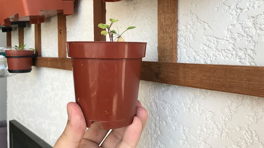
This project’s planter is rather small, just 9 centimeters in height, and weighs around 300 grams. This particular plant requires a fair amount of sunlight for growing so hanging it on a sunny wall is ideal. For this, we need a wall mount!
The overall goals for this project are:
- Create a wall mount tough enough for the planter while using the least amount of material possible.
- Design a cool, organic-looking model, as this will be 3D printed home decor and we’d like good aesthetics.
Now that we understand what the project is all about, let’s get started with the tutorial.
Step 1: Preparation
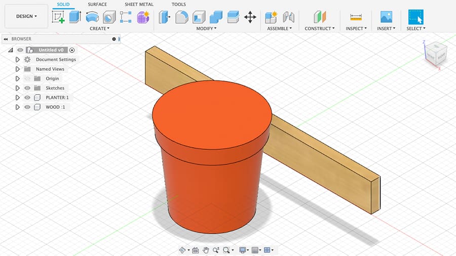
Before diving into the generative design environment, it’s a good idea to create a model of the environment where the new part will be inserted. This modeling should provide some clarity to the entire project and the parts that’ll be used by the generative design study.
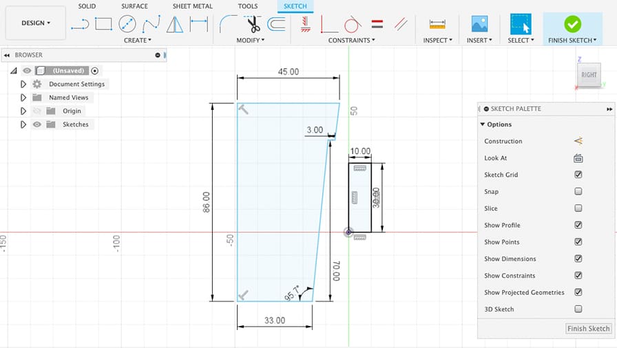
In a new Fusion360 project, model the planter and a wall as shown. The latter is actually a strip of wood to which the designed part will be screwed later, but for the purposes of this tutorial, it serves as a regular wall. Here you can model your own planter but feel free to use our own as an example.
The planter sketch dimensions are displayed in the image below and we used the revolve feature for creating the body.
There’s no need to shell the model so place the planter relative to the wall as it will be positioned with the new wall mount.
This step should make the interface geometry creation easier as we’ll see next.
Step 2: Creating the Interface Geometry
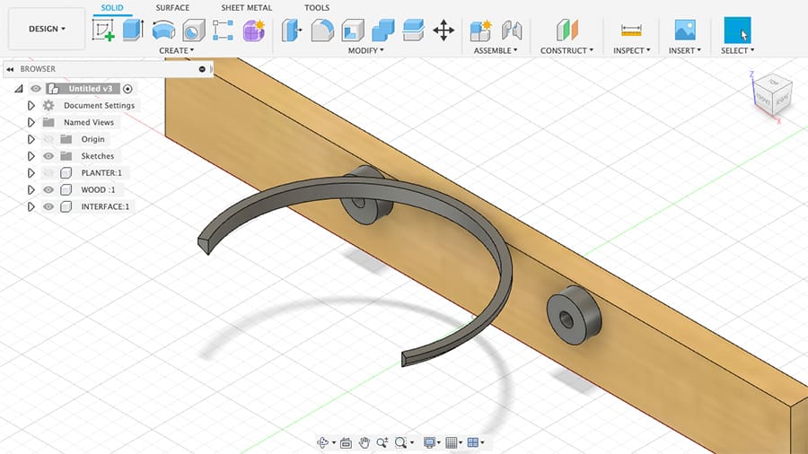
As mentioned earlier, the generative design tool will develop the model from scratch. Still, a so-called interface geometry is required to guarantee the new part will interact with the other bodies the way we want. For example, we’ll be using a couple of M5 wood screws to attach the mount to the wood, so we must create mounting surfaces that’ll work with these fasteners.
Note that the interface bodies, also known as preserved geometry, are maintained by the generative design study and will be kept unchanged in every design solution.
Let’s start with the wall interface. For now, you can hide the planter body to make this step easier.
- For this wall mount, two rounded 15 mm bodies spaced 80 mm apart should be enough for supporting the small planter. Make sure to include 5 mm center holes for the M5 fasteners and to make them extrude 6 mm for adequate thickness.
- For the interface between the mount and the planter, create an almost semi-circular geometry that’ll hold the planter by that small step near the top. Feel free to create any attachment you know will work.
Step 3: Creating the Obstacle Geometry
We’ve now reached the point where we’ll start using the generative design environment! While the interface geometry will provide the starting steps for the new design, we still need to inform the software where it can’t build. This is called obstacle geometry.
The obstacle geometry for this study will be comprised of everything other than the interface bodies, including the planter and the wall. In addition, we need to make sure that the new part has enough room for the fasteners and a screwdriver to screw them in. This is the geometry we’ll be creating next.
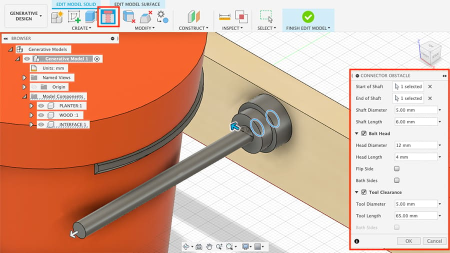
To do that, switch to the generative design environment by clicking on the top-left button that currently says “Design”. One of the first features, from left to right, reads “Edit Model”.
With this feature, we’ll create and remove bodies within a generative design study and these changes won’t take effect outside this environment. Let’s create the obstacle geometry using this tool.
- Click on “Edit Model”.
- Go to the “Connector Obstacle” tool as shown above.
- Select both the front and back edges from one mounting geometry. A new body will be created, filling this hole. This represents the screw body.
- On the “Connector Obstacle” window, check the “Bolt Head” and enter the diameter and height of the screw head that will be used.
- Just below, check “Tool Clearance” and enter the clearance required by a screwdriver to access this screw.
- Click “OK” to finish.
A new body will be created which we’ll later assign as an obstacle for the wall mount. Repeat these steps for the other mounting body or use body mirror, then pattern. Click on the green checkmark “Finish Edit Model” to close this tool.
Step 4: Defining the Preserve & Obstacle Geometry
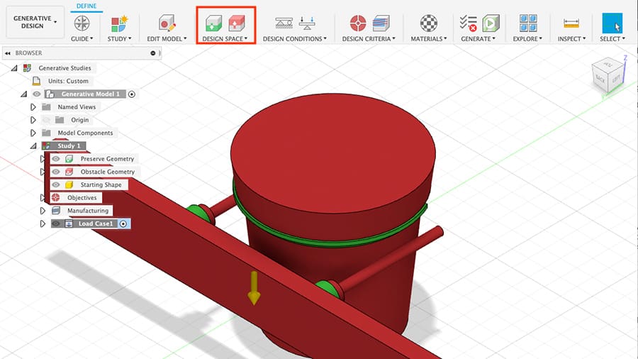
We’re finished creating parts for now and it’s time to set the parameters for the generative design study.
We’ll start by telling the software which geometry needs to be preserved and what are the obstacles. We already know that, but Fusion must be informed too.
Let’s begin with the interface geometry.
- On the top toolbar, click on “Preserve Geometry” as shown.
- Select all the interface bodies: both the mounting geometries and the semi-circular part.
- Click “OK”. These parts will turn green, meaning that these will be preserved during the new part development.
Next, we’ll handle the obstacle geometry.
- Click on “Obstacle Geometry” and select all remaining bodies: the wall and planter. (Both bodies represent the screws and screwdriver clearance that were already automatically selected.)
- Click “OK” and they should become red, showing and confirming they’re flagged as obstacles.
Step 5: Setting the Design Conditions
Moving forward, let’s input the boundary conditions and constraints. We must inform the software which geometries are fixed (and where) and what forces and loads they are subjected to.
- Hide all obstacle geometry, for now, to make this task easier.
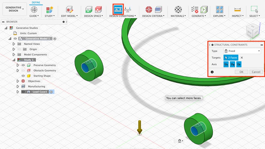
- Click on “Structural Constraints”. Leave the type as “Fixed” and select the surface inside each mounting hole.
- Click “OK”.
By doing this, we’re informing Fusion that these surfaces are restrained in movement, in this case, by fasteners.
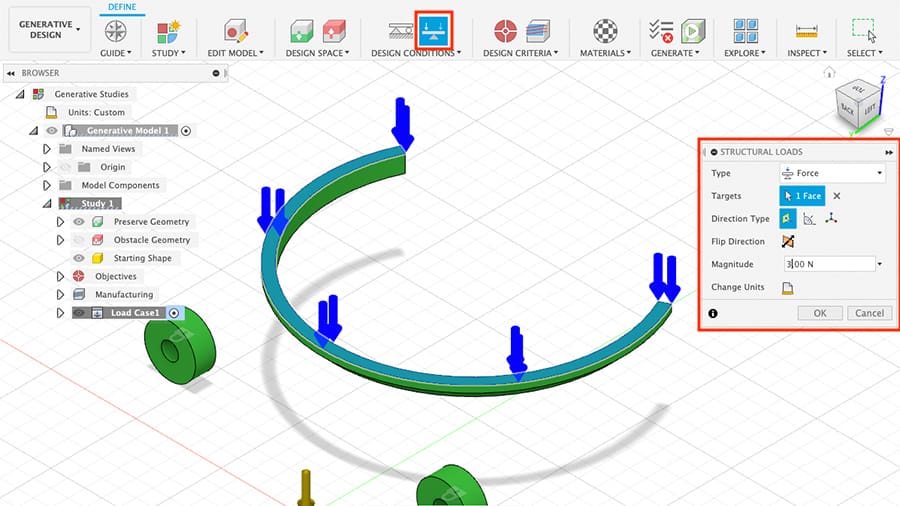
- Click on “Structural Loads”.
- Select “Force” at the “Type” dropdown menu and click on the top surface of the semi-circular body where the planter will be supported. As mentioned earlier, the planter weighs around 300 grams, which roughly translates to 3 N of distributed force.
- Set the “Magnitude” to 3 N and click “OK”.
Note that gravity is already taken into account by the software and is represented by the yellow downward arrow.
Step 6: Design Criteria & Materials
Every generative design study requires objectives for the study, usually performance based. This is what the software will strive for during development. It also needs to know which manufacturing method will be used for fabrication to ensure the new part is manufacturable. Let’s set these parameters now.
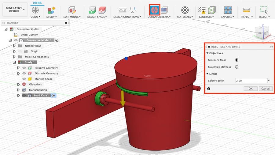
- Minimize the mass: Usually, the ultimate goal of applying generative design tools is to reduce mass as much as possible, and this is what we’re seeking with this project, too. Click on “Objectives” and mark “Minimize Mass”. Note that Fusion also allows the option of maximizing stiffness.
- Define the stress: While still at the “Objectives and Limits” window, define the “Safety Factor” to 2. This means that the new part should be able to support double the stresses and loads it’ll be subjected to. For a static planter in an indoor location, this should be more than enough to ensure it won’t break even in the worst conditions.
- Set the manufacturing type: Next, click on “Manufacturing”. Since we’re planning on 3D printing this part, check the “Additive” option. Set the maximum overhang angle and the minimum thickness your 3D printer can handle. By computing the maximum overhang angle, the software will try to optimize the model to minimize the need for support structures.
- Expand your options: The “Unrestricted” box will allow Fusion 360 to come up with designs without manufacturing constraints. Out of curiosity, let’s check that to see what the software will come up with.
Next, the software must know what materials are we considering using to make this part. This is very important since each material has different strengths and weights that must be accounted for during a generative design.
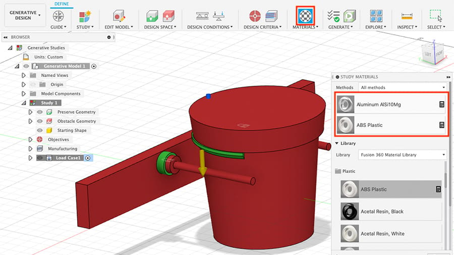
- Choose your material: Fusion 360 has a limited amount of supporting materials. For this mount, since it will be subjected to direct sunlight, it might be a good idea to 3D print it with ABS. Lucky for us, this material is supported. Select the “Fusion 360 Material Library” from the dropdown menu. Go to “Plastic” and ABS should be the very first material. Drag this material to the upper part of this window.
You’ll see that, by default, an aluminum alloy is already selected. Let’s leave it there along with ABS to see whether using metal will change the designs and how.
Step 7: Generating
Finally, we’re ready to run the study. Or, at least, we should be!
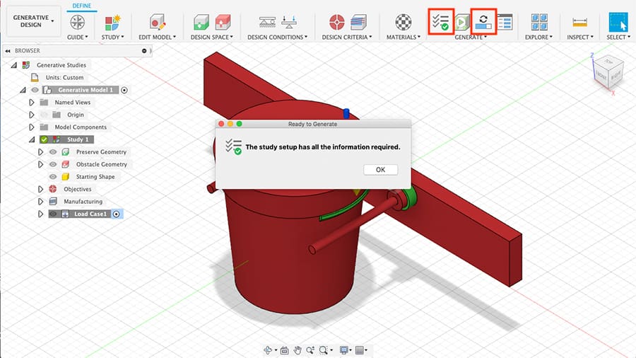
- Click on “Pre-check” so Fusion can verify if all inputs and constraints are properly set up and whether we can move forward with the study.
- If all is well, click “Generate”. (If you’re using the free version, the required amount of credits will be displayed as well as whether you have them available. If you do, go ahead and click “Generate” at the bottom.)
Now the study will be run and Fusion will start iterating different designs. Since the study is being run in the cloud, you can close the “Job Status” window and even Fusion 360 altogether and it’ll continue to process. We can follow the development by clicking on “Explore”. Note that the study could take up to several hours.
Step 8: Exploring the Solutions
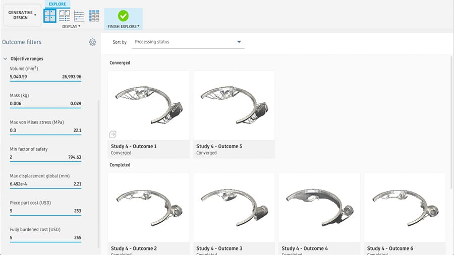
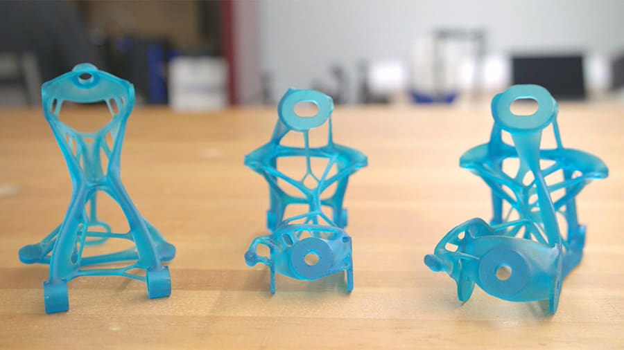
Once finished, we’ll know whether the software has found a design solution that simultaneously works with all the inputs we provided. These are known as converged designs. For our study, there were a total of two converged design solutions: one for ABS and another for aluminum.
The “Explore” environment provides many different tools to compare each design solution and helps the user to make a selection. The panel on the left filters the solutions based on inputs and outputs like manufacturing methods and objectives. While it might not be super helpful in this project, it’s an amazingly useful tool when you’re choosing between hundreds of converged solutions.

- Double-click on any given solution for a closer look. The design selected here is the ABS one, and it does seem suitable for our project.
- You can create a mesh out of this or any other design by clicking on “Create Mesh Design from Outcome” as shown.
- Once it finishes processing, export the mesh as an STL file like any other.
And there you have it! Congratulations on successfully completing a generative design study with Fusion 360!
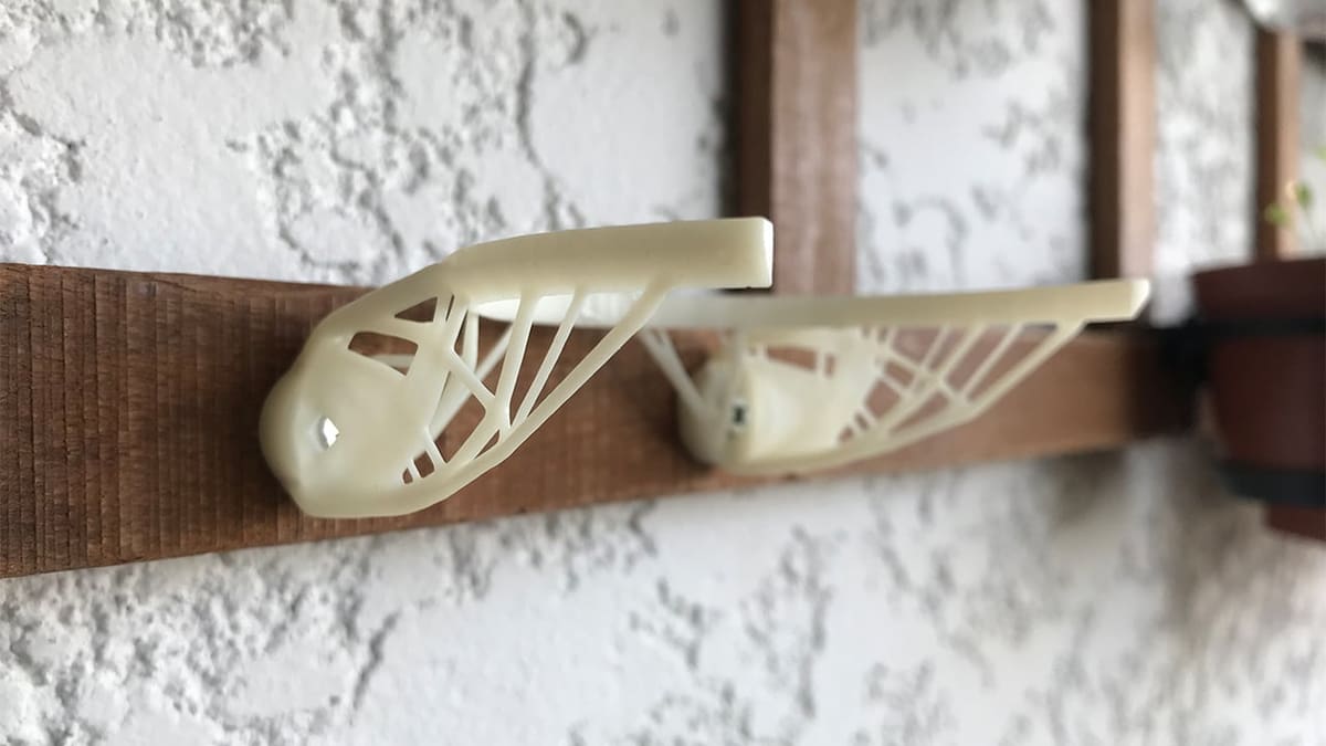
Step 9: 3D Printing & Testing
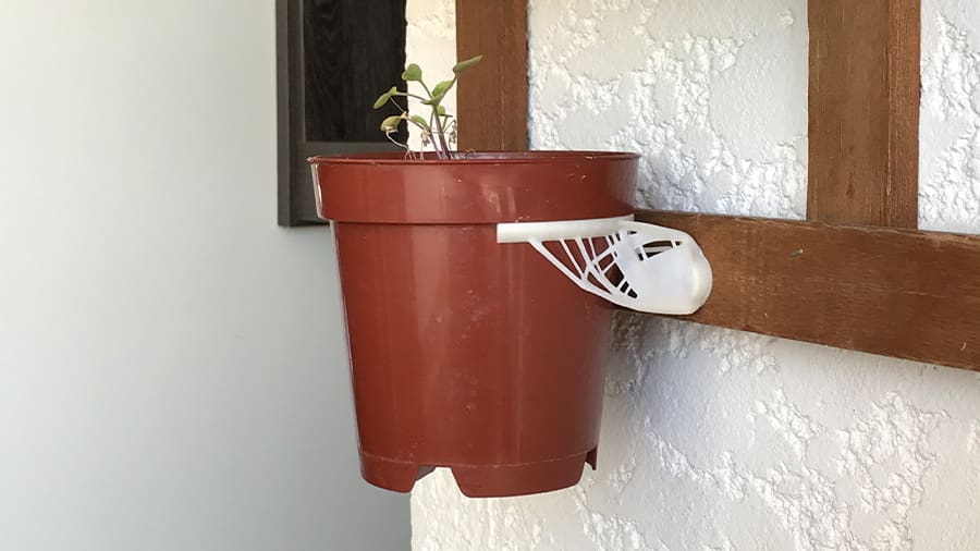
Now for the fun part: materializing the newly developed design and putting it to test. The wall mount looks very sleek and will definitely be a conversation starter. Installation was pretty easy since we planned ahead and left enough clearance for the screwdriver.
At first, the mount did look fragile, but, once strapped to the wall, it instantly gained rigidity. The whole assembly seems tough enough and the planter fits perfectly. Mission accomplished!
License: The text of "Fusion 360: Generative Design – Hands-On Tutorial" by All3DP Pro is licensed under a Creative Commons Attribution 4.0 International License.