Fusion 360 3D Printing Tutorial: 5 Steps to Success

Fusion 360 is great for creating 3D prints, and some simple strategies can make it much easier. Just follow five easy steps!
Fusion 360 is among the most popular CAD programs for hobbyist and amateur 3D printing projects. It offers a full array of 3D modeling features for creating parts from scratch and comprehensive mesh editing tools for tweaking that model downloaded from the internet.
When creating new parts for 3D printing, we should always keep in mind the specific characteristics of the printing process. Sometimes, simple design choices during the 3D modeling stage can make life much easier when 3D printing parts, even increasing the chances of a successful print.
With that in mind, this article follows our previous Fusion 360 3D modeling tutorial, where we created a simplified model of an off-road vehicle. This time, we’ll be optimizing its design to make it more 3D printing friendly and then export it in an appropriate file format.
Part 1: Avoiding Supports
Let’s start with one of the biggest villains in 3D printing: support structures.
Okay, that might be a bit too dramatic, but supports structures truly are undesirable features that increase print time and produce plastic waste. Additionally, they have the potential to ruin the surfaces of prints, leading to more post-processing time.
In the end, it’s not always possible to completely avoid support structures, but we can try to minimize them as much as possible.
As a first rule of thumb, we should always consider model orientation when designing parts – that is, how parts will be positioned during printing. This should, among other things, try to eliminate overhangs and bridges, or at least reduce them to a minimum.
Still, that’s not always an easy task, and often we have to make adjustments after the model is completed. The following are a few tips and strategies to help.
Splitting Models
Doing all we can to minimize the number of support structures, sometimes the best option is to split the model into a few parts and print them separately.
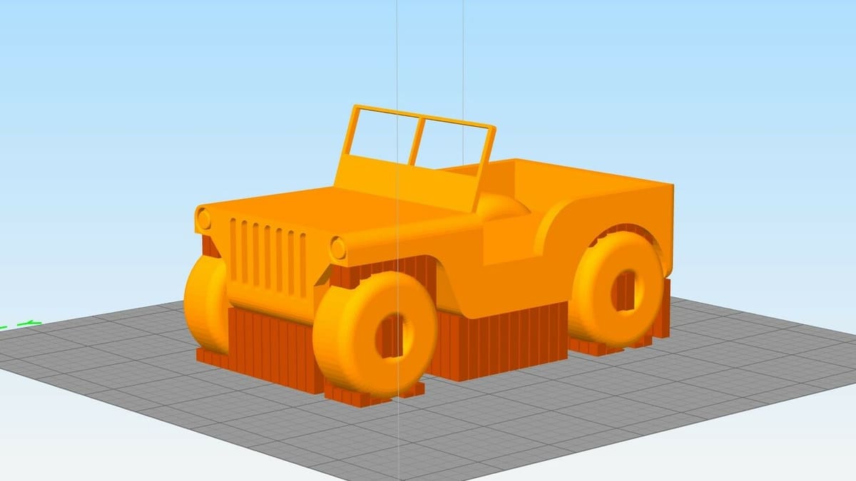
Let’s consider the off-road vehicle we already designed.
If we were to 3D print the model as-is, many support structures would be required underneath it, including all around the wheels. In fact, if you try to visualize all of the practical orientations in which it can be printed, the four wheels will always present problems in terms of supports.
In this case, we would be better off printing the body and the four wheels separately – each with its own support-optimized orientation – and then gluing them back together afterward. So let’s focus on one side of the vehicle first, separating both the front and back wheels in one single operation.
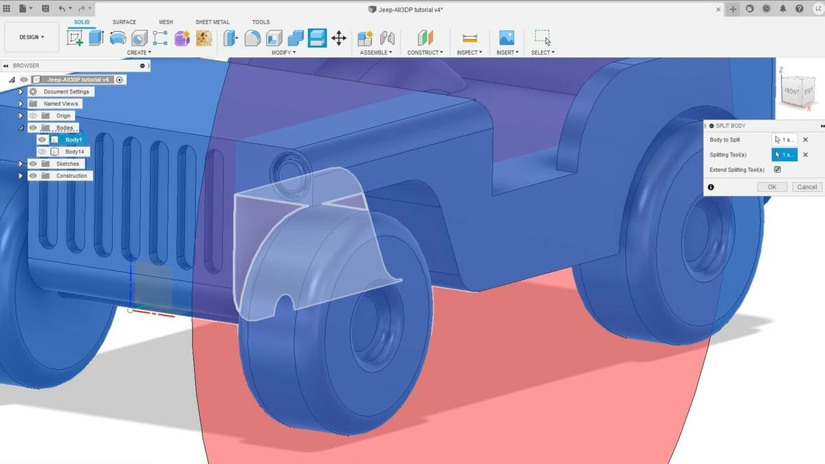
To do this, we’ll use the “Split Body” feature, which separates whole bodies via a particular plane or surface.
Split Body
- Select “Split Body” from the toolbar.
- Click on the model to select it. This will flag which bodies will be split.
- Next, in the feature window, click on the “Select” button next to the “Splitting Tool(s)” setting. This will prompt us to select the cut plane or surface.
- Click the surface where the wheels’ axes attach to their main bodies, as shown above. Note that the entire plane will be highlighted in red, so you can double-check if the cut will in fact separate the parts we want.
- Click “OK” or press Enter.
Sometimes, simply splitting a model in half is enough to avoid support structures. (Consider an egg-shaped part.) You would then lay the newly created flat surfaces directly on the build platform and assemble or glue them together post-print.
For our vehicle, however, this strategy isn’t enough; we need to separate several small parts to avoid supports as much as possible.
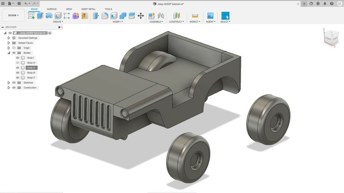
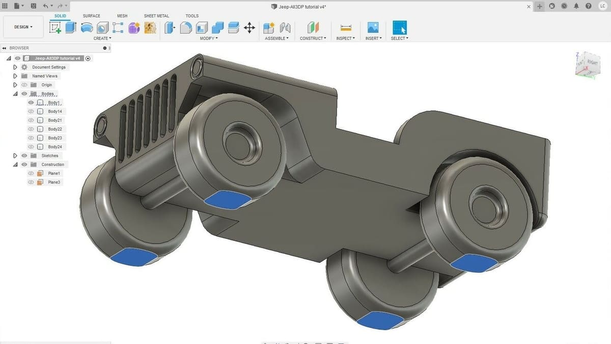
If you look in the “Body” folder under the browser, there should now be four bodies there instead of one: the original main body, the front and back wheel assemblies, and a part of the chassis that was carved out along with the wheels. (You can toggle the visibility of each to identify it.)
Although all of these parts are in the same places, they’re no longer connected, and if we were to export everything for 3D printing, we would end up with four STL files. Since we don’t want or need to be printing and gluing so many parts, let’s patch the main body back together.
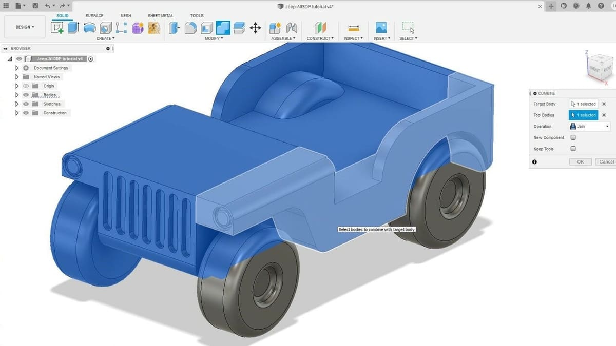
Combine
- Select the “Combine” tool from the toolbar.
- Then, select the two sliced parts of the main body.
- By default, the “Operation” setting should be set to “Join”, which is exactly what we want.
- Click “OK”.
And that’s it. The two wheels on one side should be detached, whereas the main body is one whole piece again. To separate the other two wheels and to practice a bit, repeat the procedure on the other side of the vehicle.
Fillets & Chamfers
Now that the model is stripped of the features causing the worst support structure problems, we can choose a proper orientation to avoid even more of them. For example, let’s say we print it in the vertical position, with the back of the vehicle flat on the build surface. (See the image below.) This might not look like the best orientation now, but we do still have a few cards up our sleeve.
In this new orientation, we have more than a few overhangs greater than 45°, which will be difficult to print without supports. Let’s figure out how to deal with them.
In our 3D modeling tutorial, we learned how to use the Fillet feature, and now we’ll use a very similar one: the “Chamfer” feature.
In carpentry, chamfers are bevel-like structures that ease sharp edges and corners. In 3D modeling, however, chamfers can also be used to add material between two connecting surfaces, and that’s exactly what we’re about to do here.
First, let’s deal with the biggest overhang in the main body: the one inside the vehicle, where the vehicle’s dashboard would be.
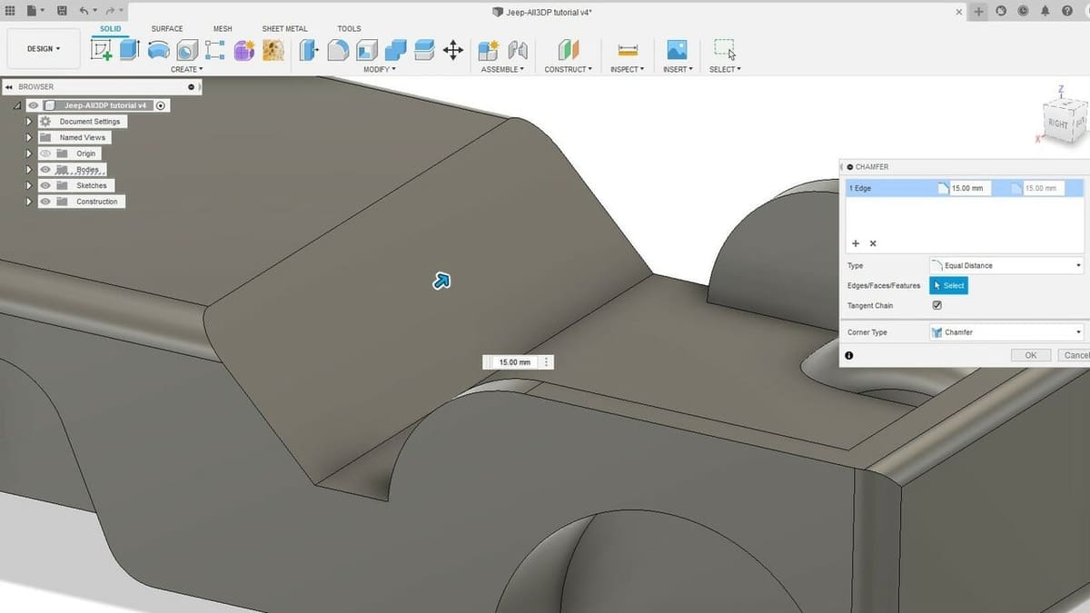
Chamfer
- Select the “Chamfer” tool located under the “Modify” tab in the toolbar.
- Then, select the edge that joins the vehicle floor and the dashboard panel.
- Pull on the blue arrow or enter 15 mm.
- Click “OK” or press Enter.
By default, the chamfer we just created will be at 45°, enough for most 3D printers to build without any support structures. Sure, we made a significant change on the model, but this shows how chamfers and fillets can reduce and even eliminate the need for supports altogether. (And you can always play around with the infill as needed, later.)
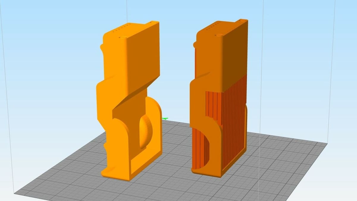
If we apply fillets and chamfers to all of the other overhangs in this orientation, the total reduction in supports structures is massive, as you can see in the image above. For the record, we added fillets to the wheel axis under the vehicle and the rounded chassis near the back wheels.
In this orientation, the total filament required was reduced from around 131 grams to 83 grams, and according to this slicer, the build time was also reduced from approximately 22 hours to about 14 hours. That’s quite an improvement.
Part 2: Improving Adhesion
Now, let’s say you don’t really care about using support structures and just want to print the vehicle as-is. That’s okay, too, since the majority of the support will be located underneath, and so these surfaces should be mostly hidden.
Still, 3D printing rounded features like these wheels can be tricky, as there’s only a tiny surface of contact between them and the bed. Bed adhesion is one of the major sources of failure in 3D prints, and printing this model could prove to be a headache.
Let’s try and alleviate that by creating a slightly bigger surface area between the wheels and the bed. If you’ve been following this tutorial up to now, let’s roll the model back to the point where all four wheels were still attached to the model.
To do that, simply click and drag the small gray indicator in the Design History Timeline to the left until you reach the first “Split Model” operation of this tutorial.
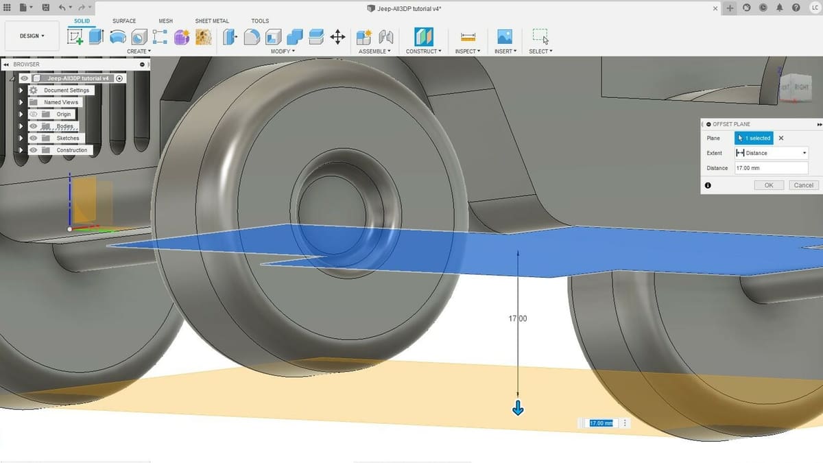
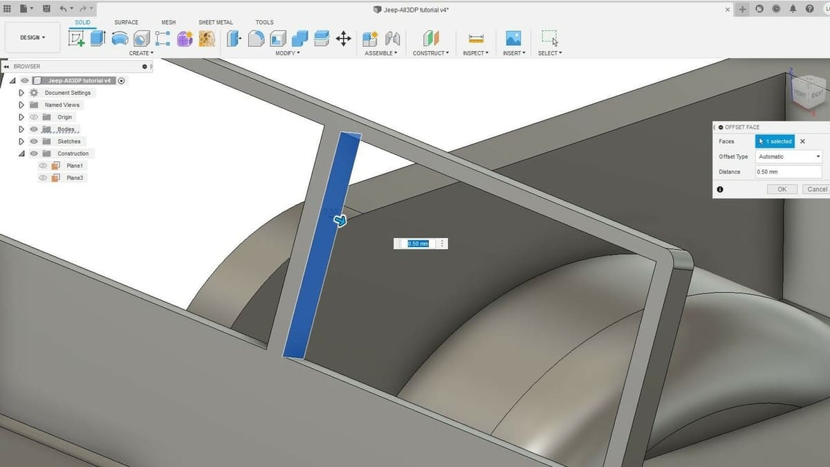
Now, to increase the surface area of all four wheels, we’ll be cutting off just a small section of them to create a flat area underneath. To do that, we first need to create a construction plane, which is a mere design aid that doesn’t interfere with solid parts. It will act as a reference for other tools.
In this particular case, we’ll need a construction plane to tell Fusion where exactly to cut the wheels. Let’s try the simplest way to create a new plane.
Construction Plane
- Select the “Offset Plane” feature under the “Construct” tab in the toolbar.
- Then, click on the lower flat surface of the model as shown above. A new orange plane will appear, along with a blue arrow and a dimension input window. This is going to be our cutting plane for the wheels.
- Either drag the arrow down or enter 17 mm. You’ll see that the final location will be just above “ground” level.
- Click “OK” or press Enter.
All that’s left is to cut! By now, you should be familiar with this tool, but let’s go at it once again.
Split Wheels
- Select the “Split Body” tool from the toolbar.
- Click on the model to select it.
- Click on the “Select” button next to the “Splitting Tool(s)” setting and select the plane we just created.
- Click “OK” to confirm.
This single operation should cut out all four wheels, creating a significantly larger contact surface that would benefit bed adhesion.
Part 3: Reducing Material
Yet another good tactic for reducing build time and filament is removing unnecessary material from models. For functional parts, this can be more complex due to the direct impact of that material on the overall resistance of parts. For more aesthetic models, however, there’s less to worry about.
Chamfers and fillets are great tools for removing material while at the same time smoothing sharp corners and edges. Yet, there are other ways, too.
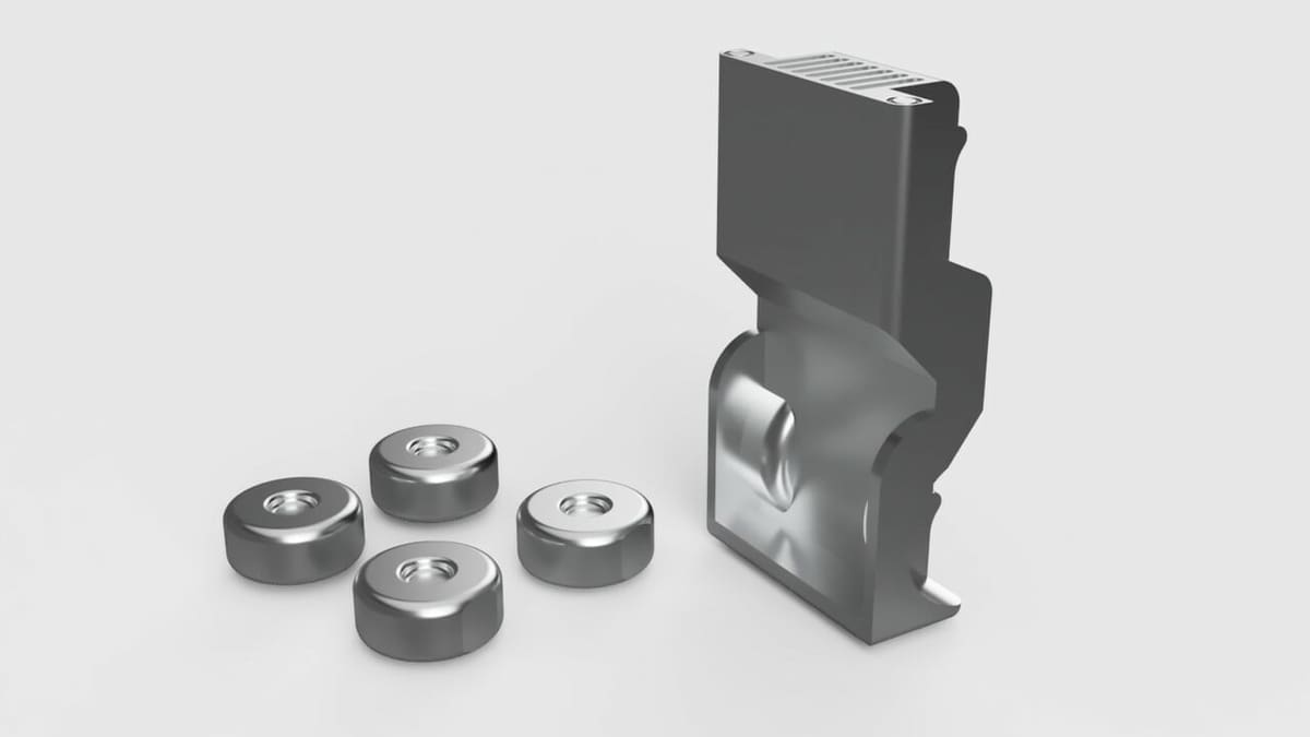
For our particular model, we could save some filament by removing material from the vehicle’s underside. This region should stay hidden most of the time, anyway.
To do that, we’ll create a Sketch and use the Extrude feature to remove material. If you want to know more about these features and how to use them, check out the previous tutorial on designing in Fusion 360.
Still, let’s go over the main steps. As a refresher, the Sketch feature allows us to create two-dimensional drawings and profiles that act as templates for 3D modeling features, like extruding.
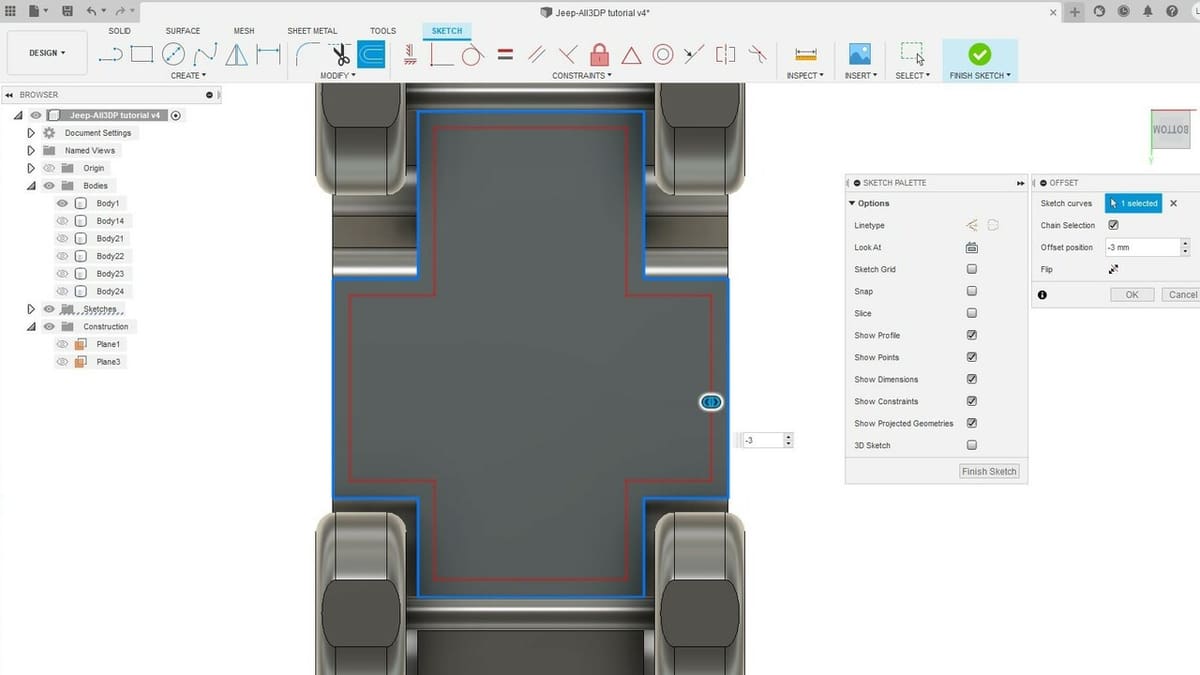
Sketch
- Create a sketch at the middle of the bottom surface of the vehicle. Note that, just by doing that, the bottom surface becomes part of the Sketch, with the perimeter lines turning blue.
- Select the “Offset” tool under the “Modify” tab in the toolbar. This allows us to duplicate a closed shape already present in the sketch and offset it by a certain distance, either inward or outward.
- Click on the perimeter of the bottom surface. You’ll note that a new perimeter will appear in red but a few millimeters away from the original.
- Either drag the blue handle or enter -3.00 mm.
- Click “OK” to confirm. You just created a new profile that matches the bottom surface perimeter.
- Click on “Finish Sketch”.
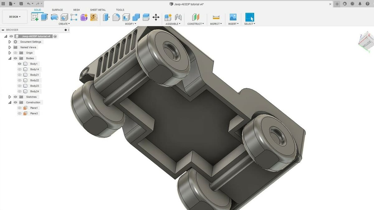
Now all that’s left is to finally remove the material using the cut operation of the Extrude feature. The Extrude feature is a very common tool for creating solid 3D bodies, but it can also be used to subtract material.
Extrude to Cut
- Select the “Extrude” feature in the toolbar. To apply the operation, we need a sketched shape to serve as a template.
- Select the internal shape defined by the new perimeter we just created.
- Enter -12 mm to perform an extrude-cut. You can, if you want, cut a little deeper, but then the thickness of the vehicle flooring would be less than 3 mm.
- Click “OK” to confirm.
Now the model should look like the image above. Naturally, you can add internal chamfers or fillets depending on the print orientation to reduce the required support structures.
In the end, this is just one example of how big chunks of material can be removed without affecting the overall look of a model. Try to think about this strategy when designing parts in the first place, as you could save yourself time later on.
Part 4: Optimizing Details
Now, before moving on to the actual 3D printing workflow, it’s always advisable to check a model for any inconsistencies or features that may prove difficult or even impossible to print. Careful attention should be paid to fine details, especially for FDM 3D printing.
Depending on the size of the nozzle, small-sized features could be printed inadequately or even not printed at all. While this kind of issue is often detected during the model slicing, it’s good to think about it while still in the design stage and not waste time going back-and-forth between CAD and slicer.
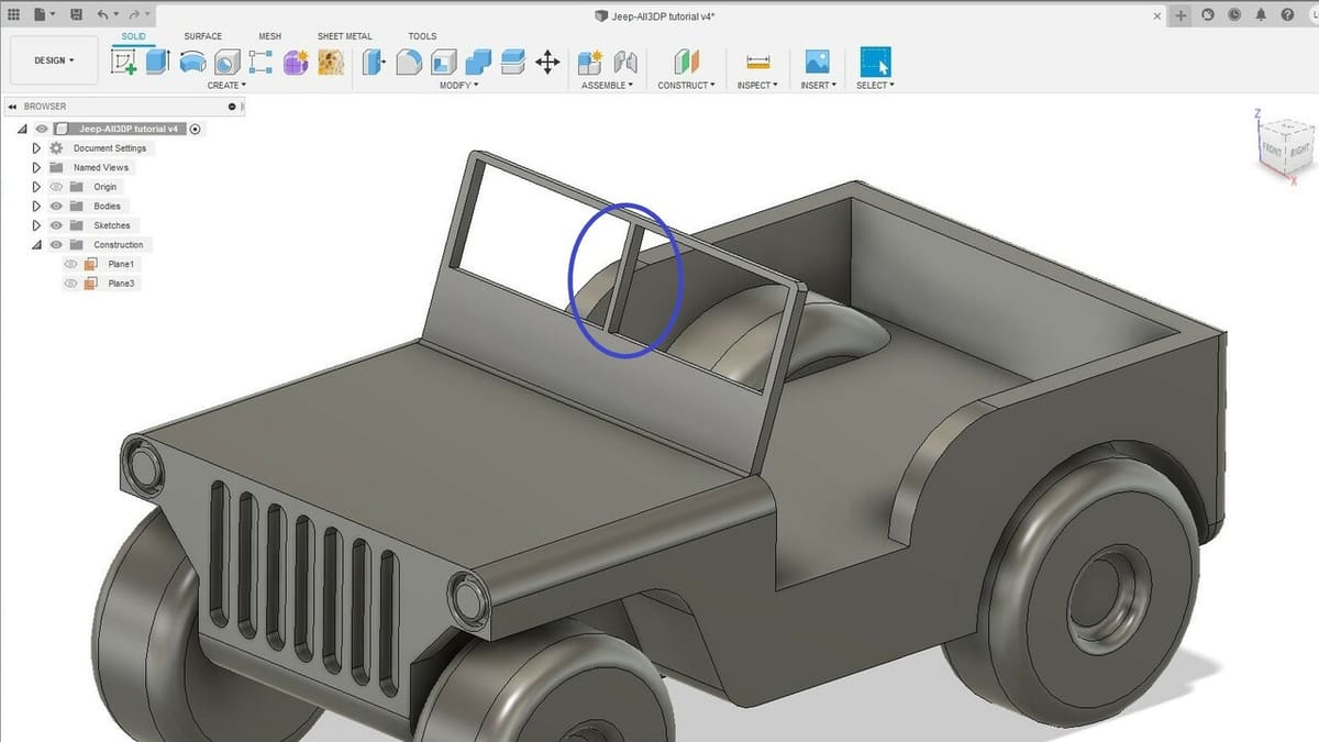
The “Measure” tool can be an excellent ally for checking the printability of fine details. Let’s take, for example, the frame of our vehicle’s windshield. This should be the finest detail of the model, and it will definitely present a problem if we scale down the entire model during slicing.
The tool is found under the “Inspect” tab in the toolbar. To measure the distance between two entities (edges, surfaces, points), simply select them one after the other. The measured dimension should pop up right on the screen, and further details can be found in the feature window.
For the windshield frame, the middle section is only 1 mm in width. A 0.4-mm nozzle might print this with only one perimeter, so say we want it to be sturdier, with at least two perimeters. The width of this frame would need to be at least 1.6 to 2.0 mm.
Instead of sketching and extruding this section, we could use a much more straightforward feature called “Press Pull”. It’s located in the toolbar, and you use it by simply selecting a surface and then pulling or pushing on the blue arrow. Alternatively, you can provide a positive or negative dimension.
The Extrude feature can indeed achieve something similar, but only with flat surfaces. The Press Pull feature is much more versatile, working very well with curved or oddly shaped profiles. It’s a quick and convenient tool for adjusting fine details.
Part 5: Exporting Printable Files
Alright! We’re finally ready to move on and get this model into a slicer. To do that, we need to export all the separate parts from our model in a polygonal mesh format.
The most common mesh format for 3D printing is the STL. It can be a very lightweight file format and is used as the default in most online 3D model repositories. It does, of course, have its disadvantages. For example, it can’t store data like measurement units or color.
Thanks to the ever-growing interest in 3D printing technologies, a new standardized and open-source mesh format was introduced in 2015: the 3MF. It was created to address STL issues and become the default format for 3D printing eventually.
Lucky for us, Fusion 360 can export 3D models in both of these formats, so you can choose whatever suits you for a given application.
Export
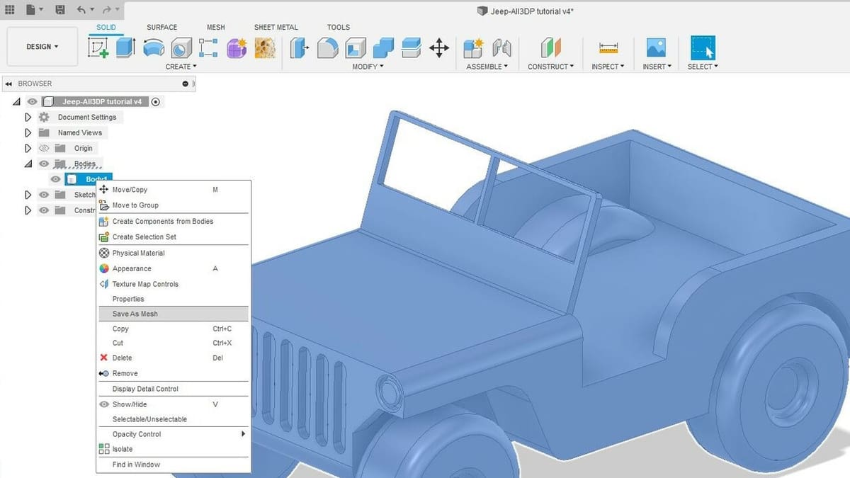
- Expand the “Body” folder under the browser located on the left side of the screen.
- To export an individual part, right-click on its name and select “Save as Mesh”.
- Choose the file format from the drop-down menu in the pop-up window.
- Click “OK”. You will be prompted to choose a folder location for your exported file.
The conversion and exporting process can be quite fast depending on your computer’s hardware and the complexity of the model. If everything goes well, the newly exported model should be ready for slicing and 3D printing.
The Built-in 3D Slicer

Speaking of 3D slicing, many people don’t know that Fusion 360 has a built-in slicing engine for 3D printing. It was released back in 2020 as part of Autodesk’s strategy to incorporate 3D printing into its machining CAM workspace.
It brings all of the most important features for getting your files to a 3D printer, but can’t really compete with the extensive control provided by Simplify 3D or the exclusive features offered by Cura and PrusaSlicer.
Still, it can be quite convenient to have both 3D modeling and 3D slicing in a single program. Moreover, it does offer some interesting features like automatic orientation to reduce support structures and a handful of unique infill patterns.
With all of that in mind, Fusion’s own 3D slicer can be an alternative to the more traditional software and is definitely worth checking out.
The Learning Continues
Congratulations on yet another completed Fusion 360 tutorial! We’ve only scratched the surface, and there are plenty of other features, tools, and functionalities to explore.
In this tutorial, we covered a few ways to make 3D models more 3D printer friendly using Fusion 360, but they’re also valid when designing models from scratch. In fact, if 3D printing is the goal, it’s always best to consider the printing process while designing.
You’ll find that there are a massive number of guides and tutorials for Fusion 360 online, be it on YouTube, using online learning platforms, or most importantly, through Autodesk.
There’s a whole world to unlock once you start playing around with Fusion 360 and STL files. Be sure to check the tutorials on how to import STL files and how to edit them in Fusion 360, as well.
Until next time!
License: The text of "Fusion 360 3D Printing Tutorial: 5 Steps to Success" by All3DP Pro is licensed under a Creative Commons Attribution 4.0 International License.