Blender 3D Printing Tutorial for Beginners

Check out our easy-to-follow Blender 3D printing tutorial to learn step-by-step how to design 3D printable models in Blender.
One of the most appealing parts of 3D printing is the ability to extrude your imagination into real-world models. You can download 3D models from various sources or choose a more exciting option: to design your own.
Enter Blender, a wonderfully accessible program that allows you to design your own 3D models and export them to be 3D printed. It’s free and open-source so that anybody can use it!
In this tutorial, we’re going to go over all the basic knowledge necessary to start creating your own printable objects. First, we’ll set up Blender to streamline the design and printing process, then we’ll take a look at several useful tools and add-ons, and finally we’ll cover an exciting project: creating a jack-o’-lantern.
By the end, you should be well on your way to developing your own designs!
Getting Started
There’s a few steps to follow to set up Blender before we start working in it.
Installation
The first step is downloading and installing Blender on your computer. For detailed instructions on how to do it, check out the online Blender Manual. This manual also has a lot of other helpful information about the different parts of Blender.
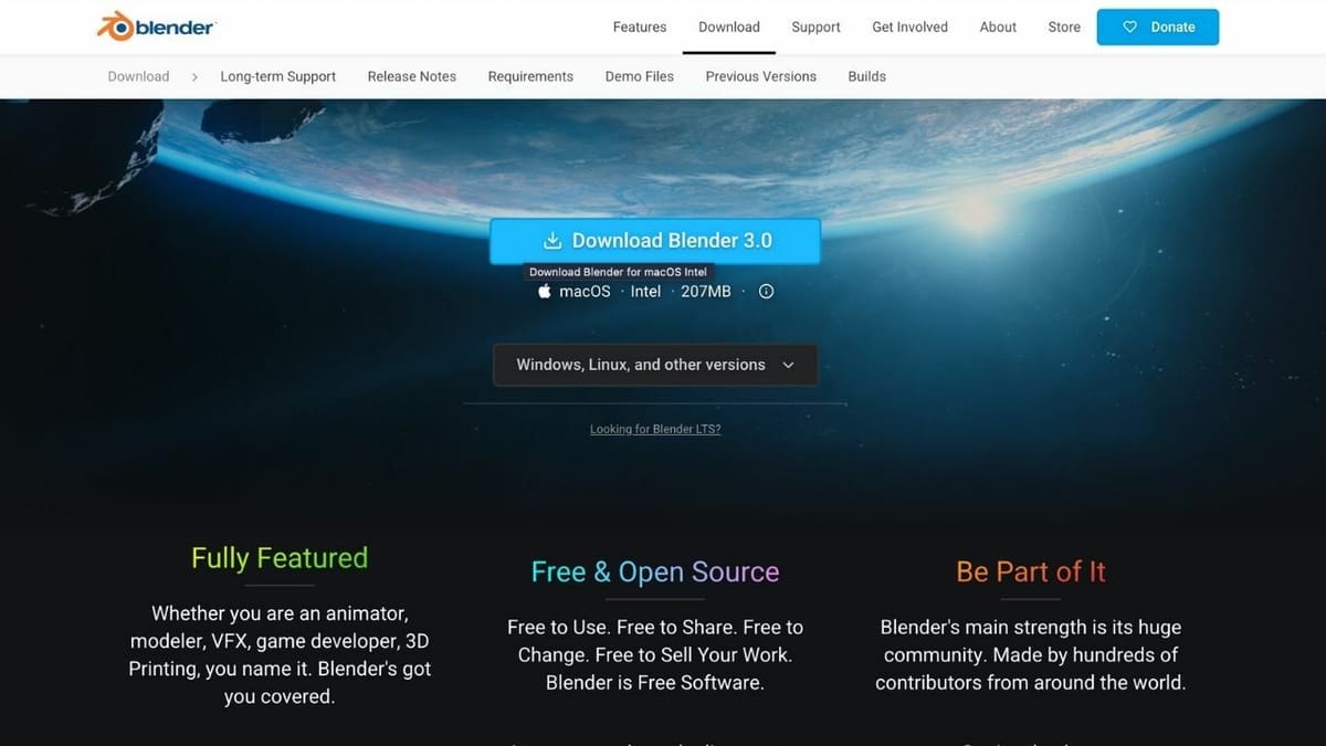
You can install Blender on Windows, MacOS, and Linux. The download page lists all the available options in a drop-down menu, and you’ll also find the list of previous versions as well as the option to try out experimental builds.
Blender Experimental is a program that contains the latest unreleased versions of Blender with new features and fresh bug fixes. However, these might be unstable, and it’s suggested that they not be used in production environments. Before you download your version of choice, make sure to check out the minimum hardware requirements.

Configuration
Everyone’s Blender UI can look drastically different because of the program’s vast range of customizations. But on the flip side, the UI may look a bit intimidating to new users who’ve never used 3D software before. Hence, it’s essential to set up Blender with the settings to make it easier to eventually 3D print your model.
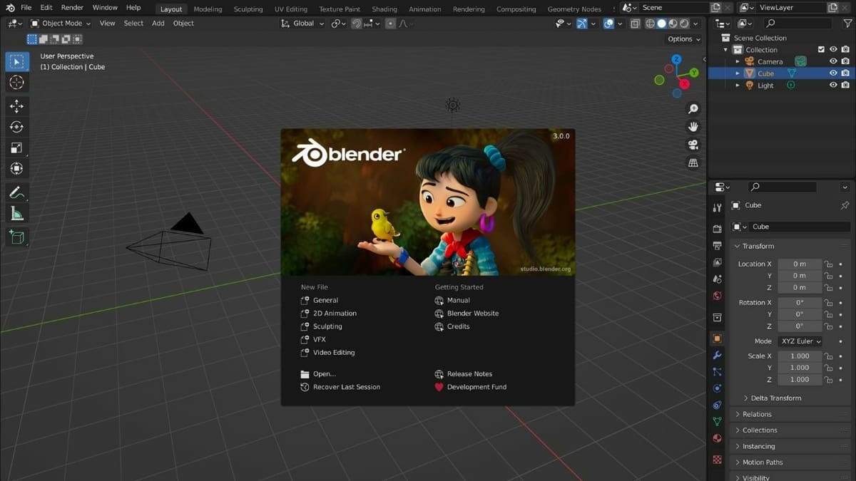
When you open Blender, the first thing you’ll see is the default splash screen. Under “New File”, select “General.” It opens a window with an object (a cube), a camera, and a light source. Right off the bat, the camera and lighting aren’t necessary to create models for 3D printing. You can choose to delete them by selecting them with a left-click of your mouse and pressing the delete key on your keyboard.
User Interface
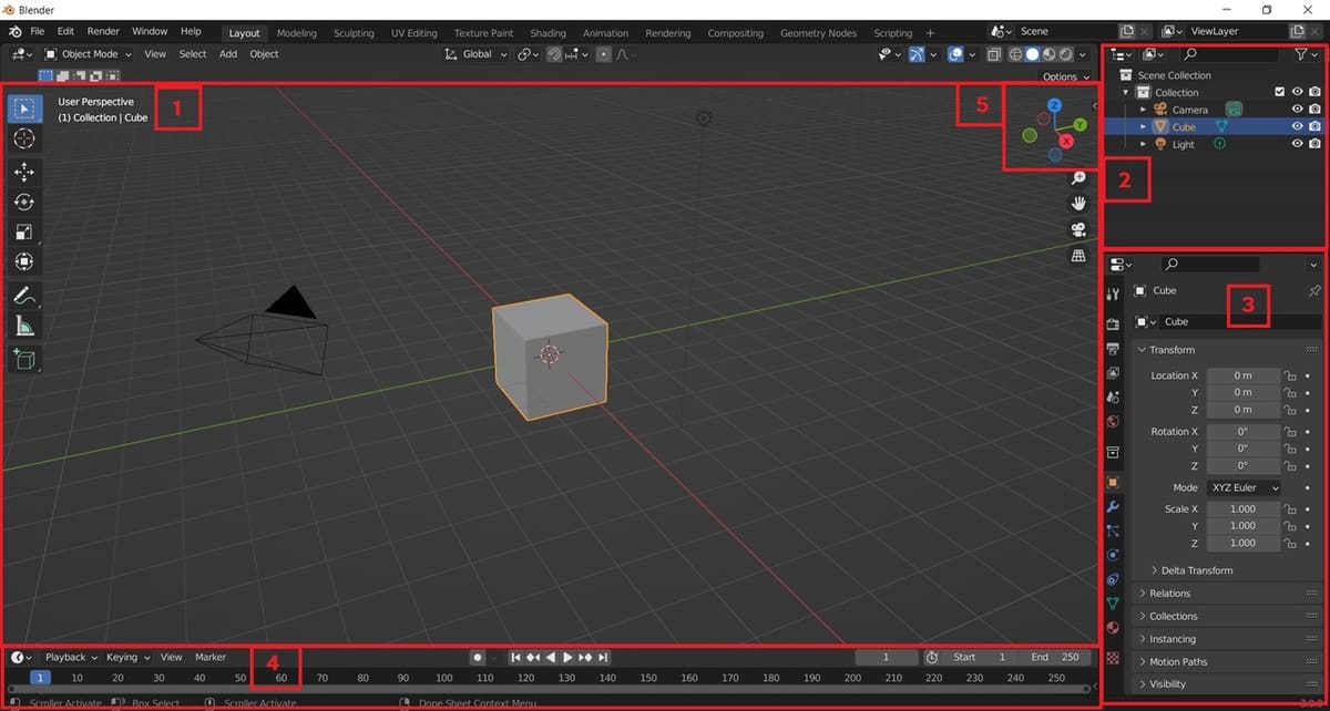
The window where the object can be seen is called the 3D Viewport (1). The menus on the top, right, and bottom are called Editors. These are the Outliner (2), Properties (3), and the Timeline (4). You can also find the navigation gizmo (5) with red, green, and blue lines to zoom, pan, or toggle in the 3D Viewport.
You’ll want to change the basic unit of measurement. By default, the program uses “Blender Units”, which can be changed to real-world units such as millimeters (mm). Do this so that your model is scaled precisely when it’s printed.
To change the unit of measurement, go to the Scene tab on the Properties editor. It’s the fifth tab from the top, which is represented by a cone and sphere. Select the drop-down menu of Units to choose imperial or metric. Most slicing software uses a metric system and will convert your model upon import, so you can choose whichever works best for you.
Navigation
Next, let’s familiarize ourselves with the basics of navigation in the 3D Viewport. This is primarily done using the left, middle, and right mouse buttons (LMB, MMB, and RMB) combined with Ctrl, Alt, and Shift. (The scroll wheel on a mouse is usually the middle button.)
There are three methods of movement: orbiting, panning, and zooming. To orbit, simply click the MMB and drag the mouse in the desired direction. Hitting “Shift + MMB” and moving the mouse inside the 3D Viewport area lets you pan (move the view left or right and up or down). Finally, to zoom, scroll the scroll wheel (MMB).
Alternatively, you can use the navigation gizmo to orbit, and beneath it, the Magnifying Glass button to zoom in or out, and the Hand button to perform panning movements. These options are explained in greater detail in our tutorial on the Viewport and the Camera View.
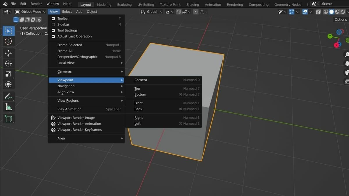
Another method of navigation that’s useful is to use the Perfect Views. These allow you to view the scene along the principal axes from different directions. They can be found in the Viewpoint under the View menu at the top of the Editor, as seen in the image above. You can also use the Numpad and Ctrl to switch to these views quickly.
Essential Tools & Operations
Before we start with the tutorial, let’s look at the most important tools and operations that we’ll be working with.
Creating Objects
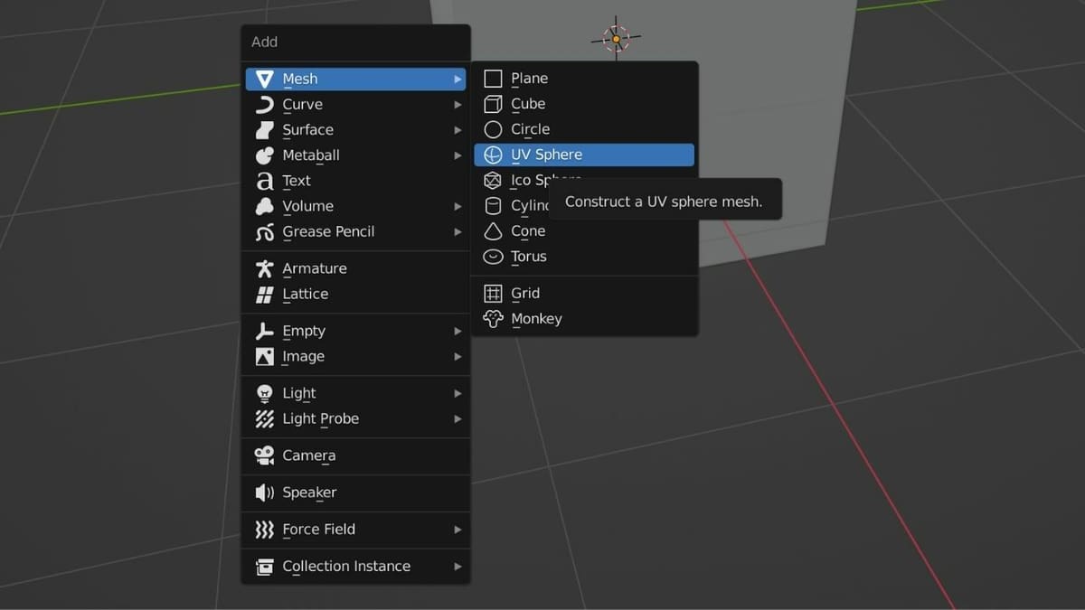
With Blender, you can create many different objects, but a mesh is all we need to create an object for 3D printing. These can be created either by selecting “Add > Mesh” from the top menu bar of the 3D Viewport or by using a shortcut (“Shift + A”). From there, we can create a variety of mesh objects:
- Cubes
- Cones
- Cylinders
- Planes
- Spheres (UV, Ico)
- Monkey (Face)
- Torus
Object Selection & Deletion
You can delete the default cube (or other objects) by selecting it with a left-click and pressing the Delete key on your keyboard.
Alternatively, you can delete objects from a particular Collection in the Outliner Editor. Each object in the collection is named, and to the right of the object names, you can see three small icons:
- Eye: toggles object visibility in the Viewport.
- Pointer: toggles object selection in the Viewport.
- Camera: toggles object rendering.
If there are objects in your scene that are only for reference, it can be helpful to turn off their selection and rendering. Toggling visibility can help you manage a complex scene or an object made from multiple parts. If you deleted an object by mistake, you can bring it back with the undo function (“Ctrl + Z”).
Transformation
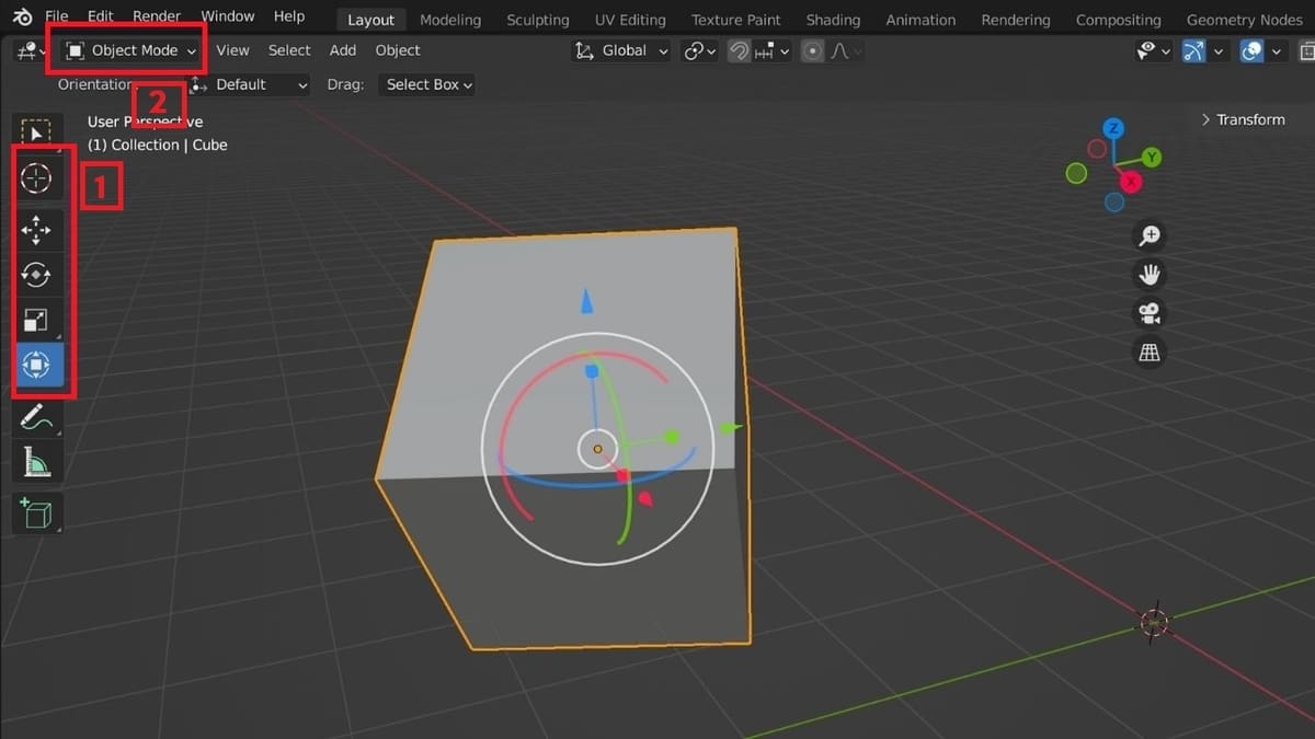
The Transform tools under the Select and Cursor options (1) allow you to manipulate objects in three ways: movement (G), rotation (R), and scaling (S). These can be selected from the menu at the top of the 3D Viewport. Alternatively, you can press ‘G’, ‘R’, and ‘S’ on your keyboard to respectively move, rotate, or scale any selected objects.
There are two ways to use these tools. The first option is to roughly manipulate an object by selecting it in the Viewport. In Object Mode (2), select the object by clicking the LMB. Turn on the Transform Tool by clicking on the icon that looks like a small square inside a circle with four arrows. Now, click and hold the LMB while hovering over one of the XYZ arrows (red, green, blue), restricting the transformation to one of those axes. If the pointer is anywhere else, the object will transform freely in all directions. Move the mouse in any direction for desired adjustments.
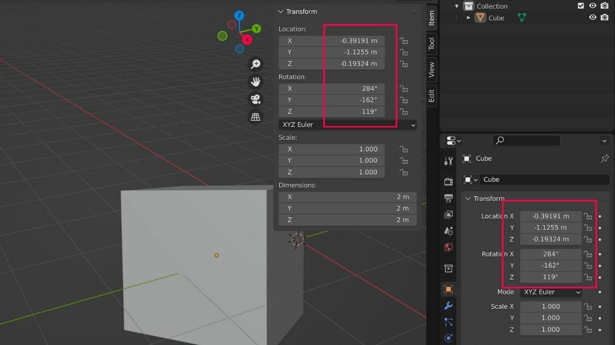
Additionally, when you click on an object using a Transform tool, properties appear on the right-hand side panel. The options are particular to each tool. This allows you to input numbers to make the exact adjustments you want. Using exact numbers ensures that the transformation will be precise. With this, you can even transform objects without using the Transform tools or opening up the properties panel.
To do this, expand the right panel of the viewport. Click the small ‘<‘ symbol in the top right corner of the Viewport or press ‘N’. This shows the object’s properties inside the Viewport, and you can make precise adjustments to its dimensions or transform it directly.
Cursor, Modifiers, & Add-Ons
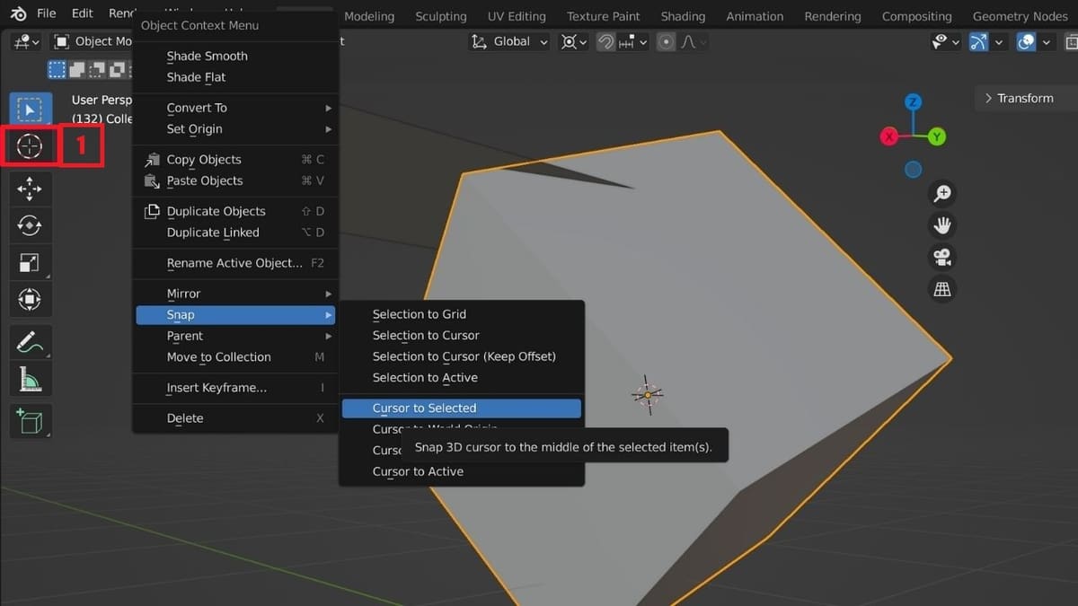
When you create an object, it will appear where your cursor is placed. To move the 3D cursor, first click on the Cursor tool (1) to enable it. It’s located directly under the Select Box and looks like a crosshair inside a circle. Now, you can place the cursor by clicking anywhere in the viewport with the LMB. To bring the 3D cursor back to the world origin, click the RMB, and hover the cursor over the Snap option. It opens up a menu that you can use to bring the cursor to a selected origin, world origin, and so on.
Finally, a brief note about modifiers and add-ons. Modifiers are automated functions that help modify an object’s geometry in a non-destructive manner. They eliminate repetitive manual jobs and automate the process (such as subdivision surfaces) without affecting the object’s base geometry.
Add-ons are specific plug-ins that let you perform particular actions. They also save you some manual work and add additional functionality to Blender that isn’t built-in.
In the tutorial below, we’ll add the Subdivision Surface modifier and the Auto Mirror add-on to simplify the design process.
Jack-O'-Lantern Tutorial
Now that we’ve covered the basics about Blender, let’s get spooky!
Add UV Sphere
While there are plenty of objects that could be 3D printed all on their own, we want to do something a little more interesting. How about a jack-o’-lantern? So, to start this tutorial, we’ll delete the default cube, light, and camera. Before you add a new object, check that you’ve set the unit system to metric and the length to millimeters (mm).
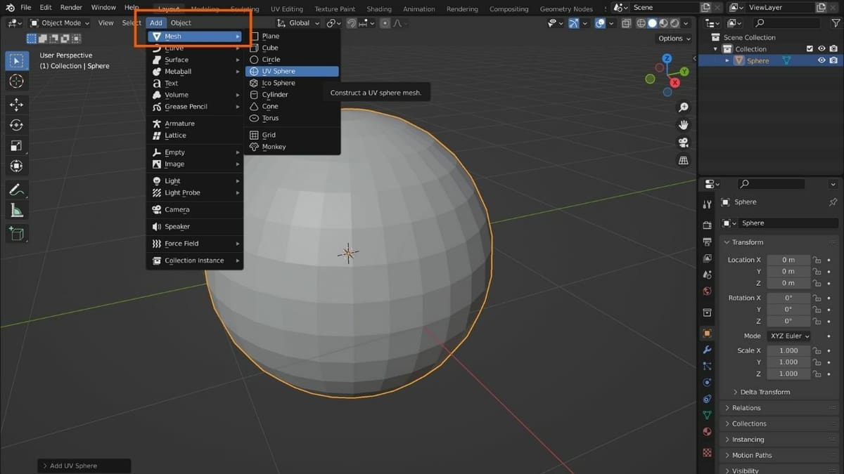
Add a UV sphere with “Add > Mesh > UV Sphere”; once added, new properties will appear on the right-hand side panel, allowing you to make adjustments. Remember that this is the only time you can make these adjustments. Once you transform or edit the mesh in any way, these properties are set and can only be changed through manual operations.
A sphere looks nothing like a carved pumpkin lantern, so let’s start by transforming the mesh.
Transforming
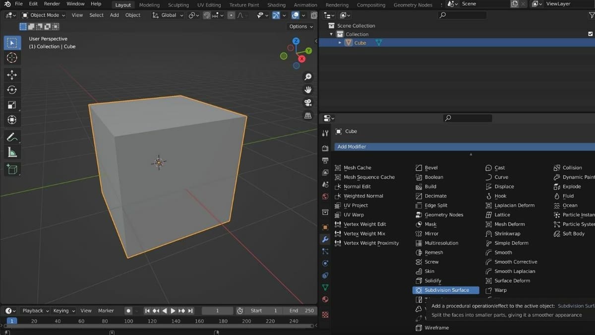
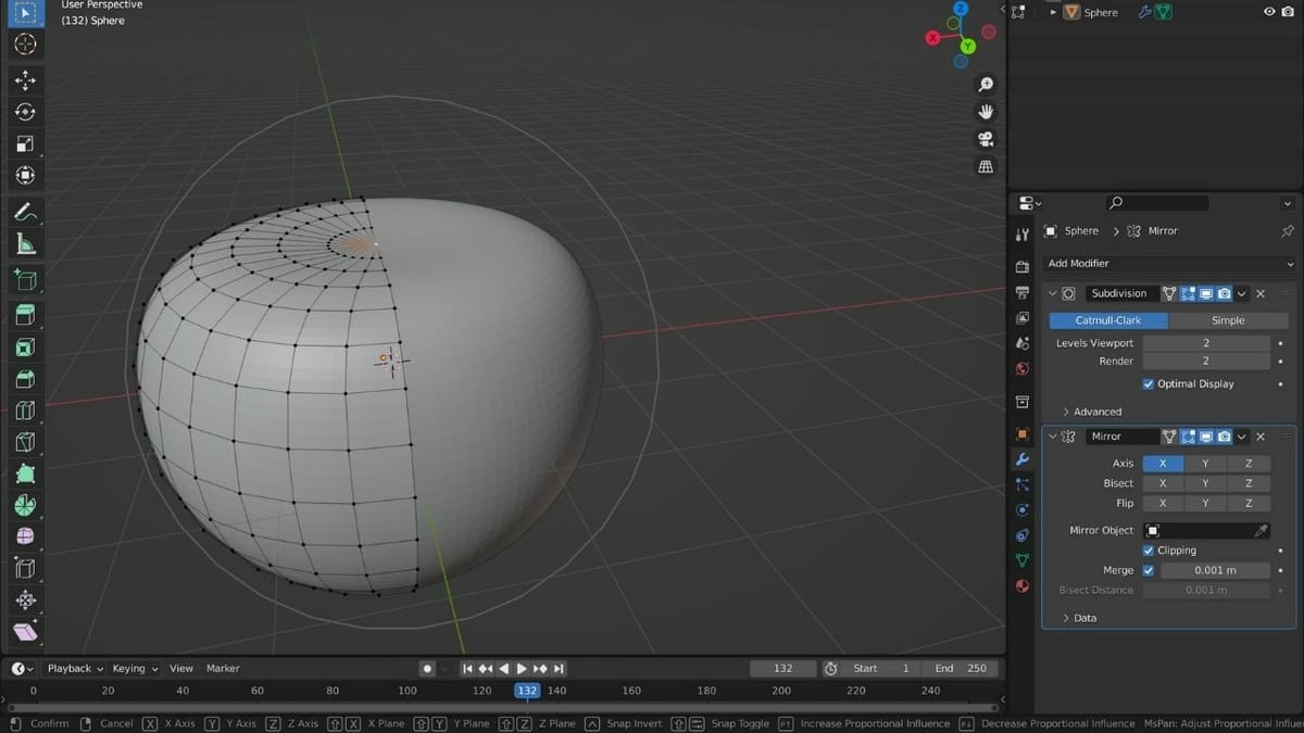
We’ll start with Modifiers. One of them is the Subdivision Surface modifier, which adds more divisions into the faces of a mesh, providing it a smoother appearance. To add it:
- From the Properties menu (right), click on “Modifier Properties,” which has an icon that looks like a wrench.
- Click on “Add Modifier,” which opens a drop-down menu.
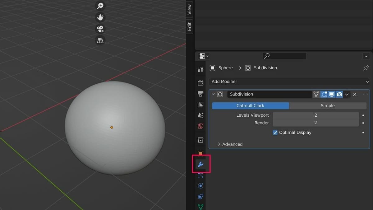
- Choose “Subdivision Surface” under the “Generate” column.
- Now, set the “Levels Viewport” and “Render” as ‘2’. Increasing the value will make the cuts smoother, and setting them as ‘0’ will result in rougher cuts. Click on the downward-facing symbol next to the ‘X’ and select “Apply”, or key “Ctrl + A”.
Note that setting the values above a specific limit may result in freezing or crashing if enough memory isn’t available.
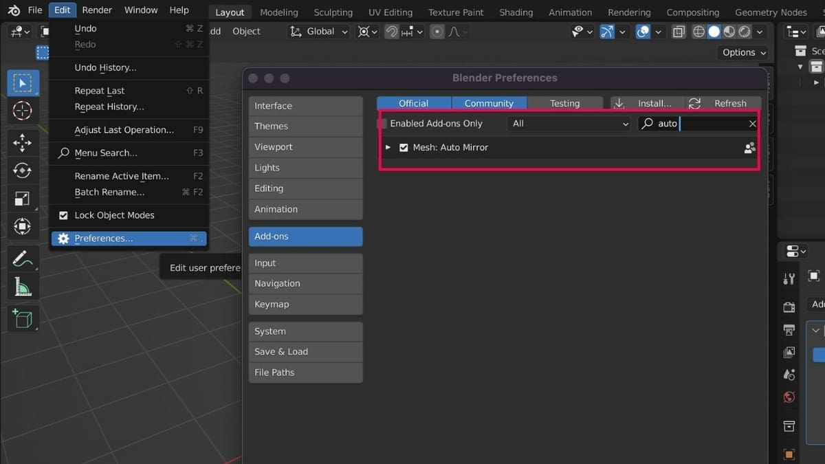
In addition to subdividing the surface, this project will be much easier with the Auto Mirror add-on. Auto Mirror does exactly what you would imagine: It mirrors mesh objects from a specific line of separation, as it automatically “cuts” an object in two and mirrors it along a particular axis. Auto Mirror will help us create symmetry, especially when it comes to the pumpkin’s eyes, nose, and spooky smile, which we’ll get to later. It also cuts the design work in half; now we only need to work on one half of the sphere, and the other half will be mirrored.
You’ll find this add-on under “Edit > Preferences > Add-ons > Mesh: Auto Mirror”. To enable it:
- With the cursor in the 3D Viewport, press ‘N’.
- Select the Edit section.
- Turn on Auto Mirror along the X-axis by clicking the “AutoMirror” button.
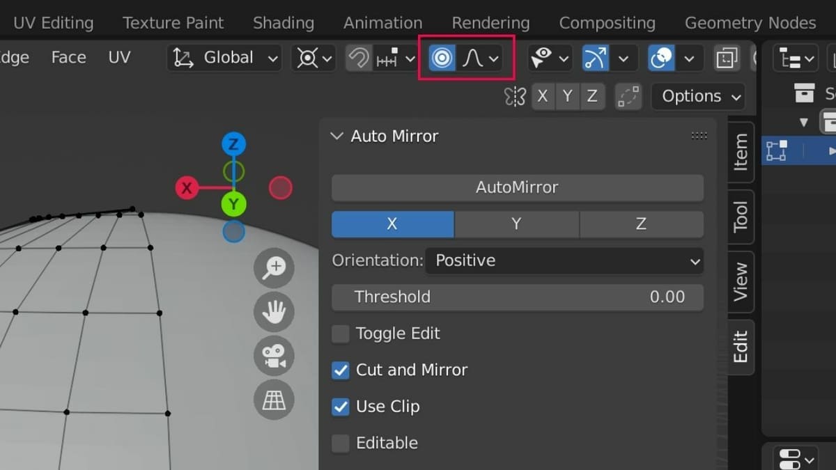
Now, turn on “Proportional Editing” by pressing ‘O’ on your keyboard. The Proportional Editing tool is generally used to bend certain areas of the surface without creating rough patches into the mesh. It looks like a dot inside a circle and gets highlighted in blue when turned on.
You can toggle it off by again pressing ‘O’ on the keyboard or by directly clicking on the Proportional Editing tool.
Editing the Mesh
With just a bit of modeling and tracing, we can quickly turn this UV sphere into a printable jack-o’-lantern.
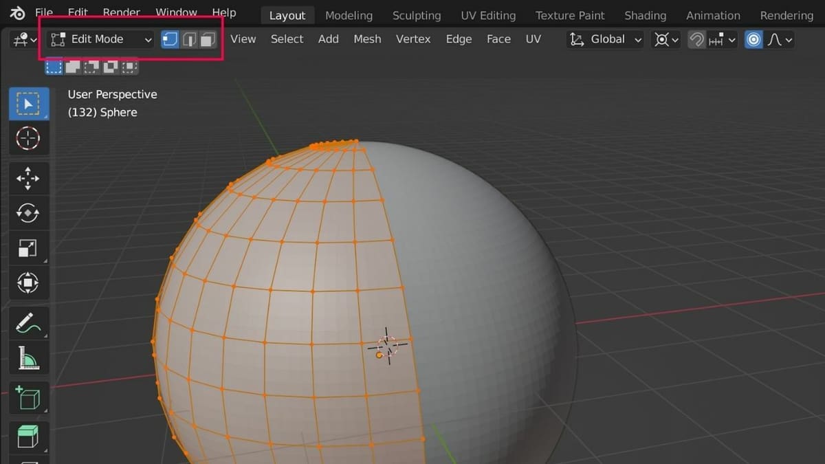
A mesh object has three main components: vertices, edges, and faces. These are what the mesh geometry is composed of. We can take a closer look at these components by changing from Object Mode to Edit Mode at the top left of the Viewport.
Edit Mode allows us to manipulate these three elements directly. Modeling in this style is often called “box modeling,” as it typically starts from a cube. However, it can also start with other primitive shapes such as cylinders and spheres.
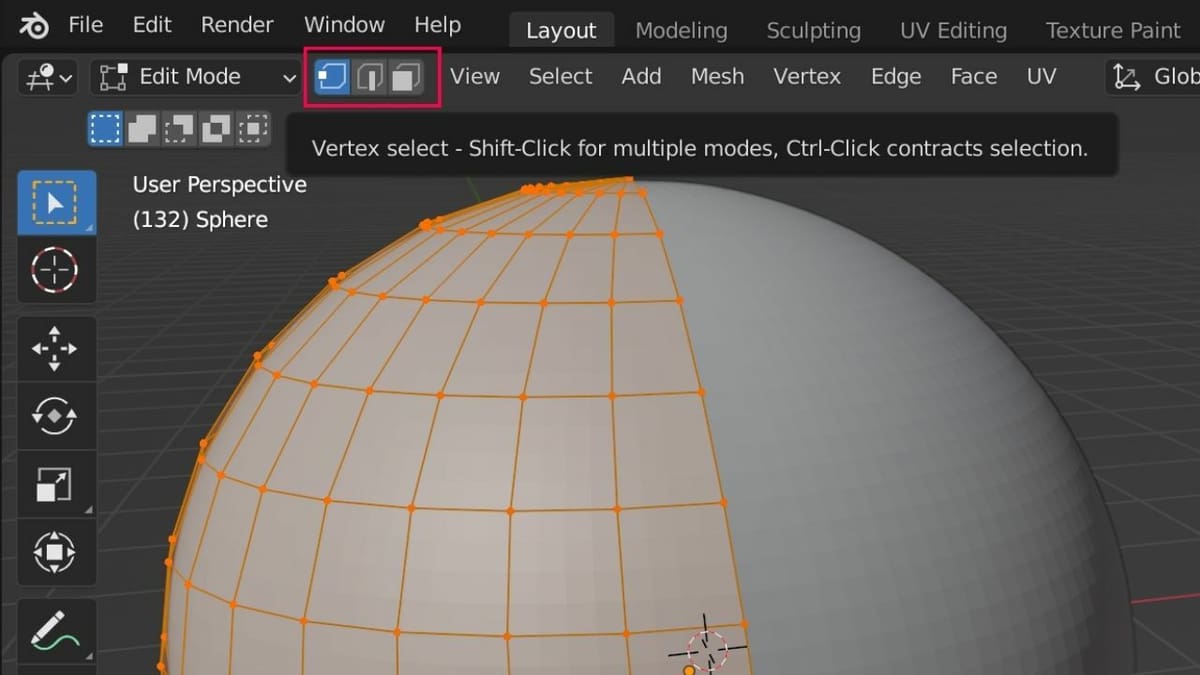
You can select between the three mesh components using the buttons on the top menu bar:
- Vertices are the individual points that make up the structure of the mesh.
- Edges are the lines that can be made between vertices.
- Faces are the surfaces created by a minimum of three lines.
A general rule of thumb is that a face should have no more than four vertices, as this can disrupt geometry flow. That’s because, when models are exported, they’re converted into triangles.
When selecting components on an object, you can use “Shift + LMB” to make multiple selections or “Ctrl + LMB”, to select along a pathway. Clicking a selected component again will deselect it.
Modeling
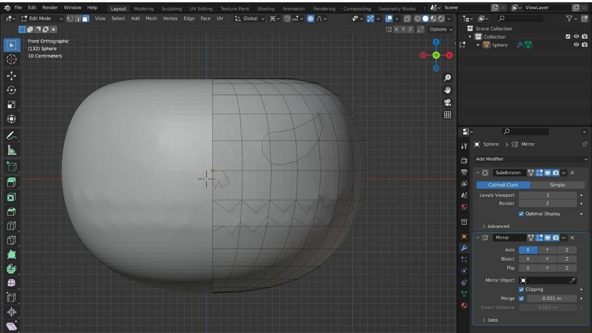
Now we need to make the top and bottom of our jack-o’-lantern somewhat flat. To do that:
- Select the Modeling window (at the top of the Viewport) and confirm that you’ve selected Edit Mode and that you’re in Vertex select.
- To make the following steps easier, press ‘Z’ to lock the movement along the Z-axis. (You can also lock other axes by hitting ‘X’ or ‘Y’, but in this instance, only ‘Z’ is beneficial.)
- Select the topmost vertex, press ‘G,’ and move it down.
- Rotate the sphere and flatten out the bottom portion using the same method.
Tracing
After we’ve got the pumpkin, it’s time to trace out the spooky smile and eyes. Anything you trace on the right half will be mirrored on the left, since Auto Mirror is turned on. To do that:
- Switch to Face select (third top-left option, to the right of Edit Mode) and Front view (Numpad 1).
- Press ‘K’ on your keyboard and a knife tool will appear.
- Start tracing the mouth by continuously clicking the LMB. Since Auto Mirror is active, starting and ending the tracing at the center edge is suggested (as seen in the image), and there’s no need to close the parts that will be continued on the other side.
- Once done, press Enter to confirm the trace. Clicking the LMB outside the sphere, or pressing Esc, deselects the trace.
- Repeat the same step to trace the eyes (remember to close these tracings) and nose individually.
Debossing the Features
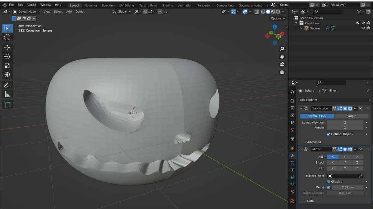
Once the tracing is done, you need to deboss the traced portions inside the mesh. To do that:
- Still in Face select, press ‘C’ for Circle Select.
- With the LMB, select the eyes, nose, and smile by clicking inside the parts. If the selection tool is too big or small, you can resize it with the scroll wheel.
- Once done, click outside the pumpkin, press Enter, and then press ‘E’. Move the mouse forward and backward to adjust.
- Click the LMB (on the Viewport) to confirm, or “Ctrl + Z” if you want to undo your actions.
Embossing the Stalk
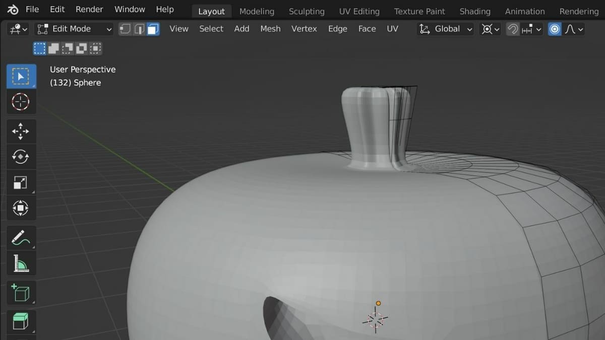
It’s time to create a stalk on top of the pumpkin. However, you should avoid using a second mesh because 3D printing objects with multiple meshes is tricky and prone to errors. Hence, we’ll emboss a stalk from the same mesh.
To emboss the stalk:
- If needed, shift the view around (for example with the navigation gizmo), to have a clearer perspective of the top of the pumpkin.
- Press ‘K’ on your keyboard and the knife tool will appear
- Trace out the stalk by clicking the LMB; draw it on the top right half and the left half will be mirrored.
- Once done, press Enter to confirm the trace.
- Now, press ‘C’, select the trace, press Enter, and then press ‘E’ and move the mouse to adjust the emboss.
- Click the LMB to confirm.
If you decide to work with more than one mesh, make sure that everything in the meshes is well attached and that the structure is watertight as a whole. You can also use a Boolean modifier to merge meshes efficiently.
Once you’re happy with your jack-o’-lantern, let’s go over how to export the model.
Exporting
Blender has a wide variety of export options, such as PLY, STL, OBJ, 3DS, and FBX, among others. Let’s check out how to export a 3D model as an STL file, which is usable with the 3D slicing software you’ll need to prepare it for printing.
You can either export it as it is or split the jack-o’-lantern in half and print the front and back sides separately. Splitting it in half will allow you to avoid using any supports while 3D printing. However, you’ll have to glue the parts together later.
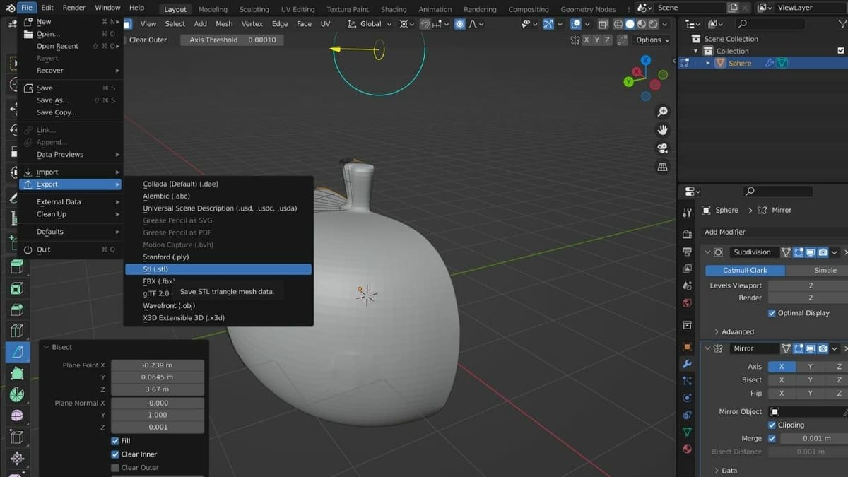
To export the complete jack-o’-lantern, simply go to “File > Export > Stl (.stl)”, and you’ll be set to slice it.
If you’d rather opt for the two parts, we’ll go over how to export it in halves.
Splitting the Model in Half
If you want to split the model, your first step is still to click “File > Export > Stl (.stl)”.
Once you’ve successfully exported the model, import it back in as an STL:
- Click on “File > Import”.
- Select Stl (.stl) and choose the file you just exported.
- Click on “Import STL” to bring it back into Blender.
Now, to split the jack-o’-lantern in half:
- Make sure that you’re in “Edit Mode.”
- Switch to the right or left viewpoint through the “View > Viewpoint” menu.
- Press ‘A’ to select the entire mesh.
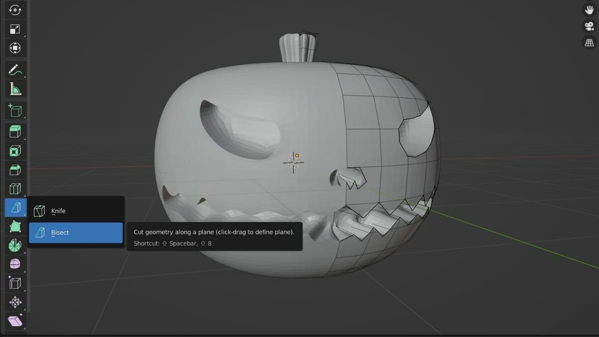
- Click and hold on to the Knife tool, which opens a drop-down menu as seen in the image above.
- Hover the cursor over the Bisect tool and release the mouse.
Finally, we’ll use the Bisect tool to split the mesh in half along the Z-axis (blue line). To do that:
- Cut from top to bottom by clicking and holding the LMB.
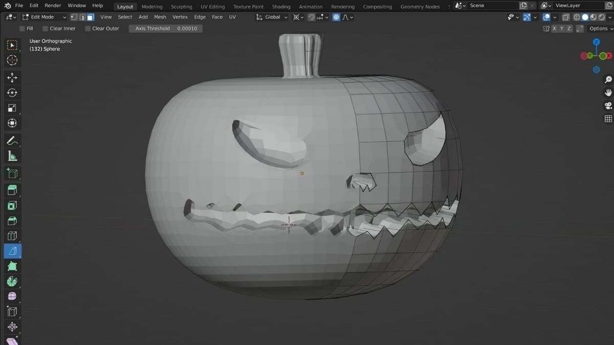
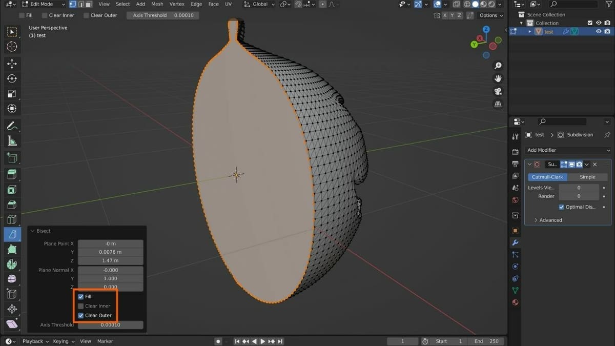
- Check on the “Fill” as well as “Clear outer” options from the bisect drop-down menu at the bottom left of the Viewport (to expand, click on ‘>’) and proceed with the export. The former fills in the cut while the latter removes the outer portion.
Once this part is exported, uncheck “Clear outer” and check “Clear inner”. Now export this too. All set! You can import each half into your preferred slicer and 3D print them.
Congratulations! You’ve just designed a 3D printable model from scratch. What will you design next?
License: The text of "Blender 3D Printing Tutorial for Beginners" by All3DP is licensed under a Creative Commons Attribution 4.0 International License.