Threads & Screws: 3D Print Them Perfectly Every Time

3D printing threads and screws that fit is a challenge. Check out this simple guide to learn how to successfully design and print them!
Patiently waiting hour after hour for a print to finish, only to then discover the custom screw you designed doesn’t fit the threaded part you have is an experience nobody wants to repeat.
Getting threads right can feel like trial and error if you’ve not done it before, but this article is going to make sure you know exactly the steps to take. With a few key design principles, you can start creating perfectly fitting, functional screws and threads straight off the print bed, and this is the place to find out how.
Key Differences
Before we get into the meat of this topic, let’s first explain what the difference between a screw and a thread is.
A screw is a fastening element used to form a joint that can be later dismantled, while a thread is the main fastening feature of a screw. Threads aren’t only used for screws though; you’ll also find them on pipes, linear drives, worm gears, and many other things too.
The common feature among threads is the way they’re formed. Every thread is a continuous helical groove of a specific cross-section produced on the exterior or interior of a cylindrical surface.
In most cases, the cross-section, or form, is triangular or trapezoidal. Triangle thread forms are mostly used for fasteners (screws), while trapezoid thread forms, a variation of square thread forms, are used for power transmission and linear drives on lead screws. To make things simpler, this article discusses only triangular-shaped threads, but everything that applies here applies to both types.
A further level of categorization distinguishes metric threads from inch threads. The former are mostly used in Europe and Asia, while the latter are used in the US and UK. To the untrained eye, they look the same, but a difference exists in the shape of the triangle and the pitch of the helix curve.
In this article, we’ll take a look at the basics of designing and 3D printing screws and threads.
Basic Terms
Before starting to design threads, there are a few terms and concepts you should be familiar with:
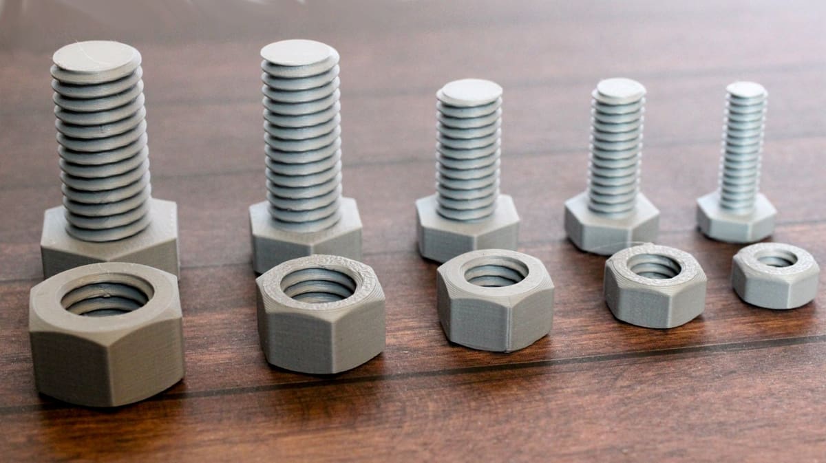
- External or internal thread: An external or male thread extends from a cylindrical surface. An internal or female thread is the exact negative of an external thread, meaning it’s carved into a negative cylindrical surface. Bolts, for example, employ external threads, while nuts use internal threads.
- Thread direction: Threads screw either toward the right or the left. Right-handed threads run clockwise, and left-handed threads run counterclockwise. If you turn a right-handed thread counterclockwise, it will unscrew. Moreover, a right-handed nut won’t screw onto a left-handed screw. Although right-handed threads are the most common, you can find left-handed threads in places like showers or sinks for the hot water handle.
- Thread axis: This is the line running through the center of the cylinder on which the thread is formed.
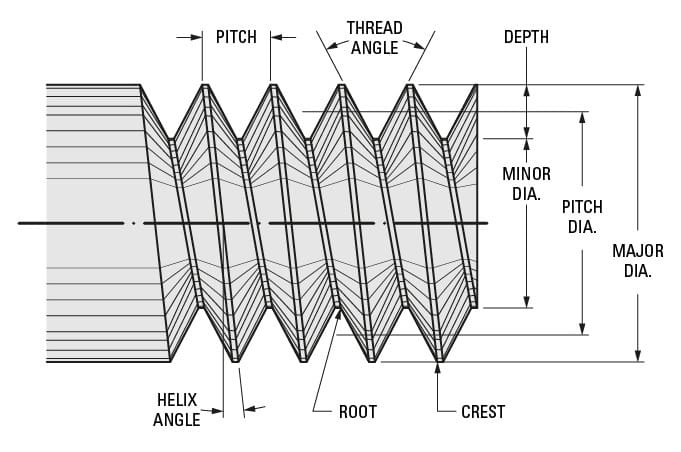
- Root: This is the bottom of the groove running around the thread body.
- Crest: This is the highest point of the thread profile.
- Major diameter: The diameter of the cylinder that encircles the crest of the external thread or the root of the internal thread is known as the major diameter. This cylinder is concentric to the thread axis.
- Minor diameter: This is the diameter of the cylinder that encircles the root of the thread in an external thread or the crest in an internal thread. This cylinder is concentric to the thread axis and the major diameter. The minor diameter is also known as the “drill size diameter” when referring to inner threads.
- Pitch: This is the distance between equivalent points on adjacent threads. For example, the distance between two neighboring crests of a triangular thread.
Designing Threads
When designing threaded elements, you’ve two possibilities. You can use the existing toolboxes in CAD software that contain models of many commercial machine elements. The tools available in toolboxes vary software-to-software, and some may have to be purchased.
Alternatively, you can model threaded elements from scratch. To model threaded elements from scratch, Fusion 360, for example, provides a simplified thread generation function. Other CAD programs have tools of varying degrees of similarity.
Regardless of your method, the important thing is to understand the basics. It’s not only about how to use CAD software but also about knowing the design rules for threads. Therefore, before getting into how to model threads, let’s talk about thread regulations.
Thread Regulations
All commercial screws are standardized. For example, an ISO M4X20 Bristol Allen screw has an already defined pitch, angle, and tooth dimensions. Therefore when you model a threaded element, the dimensions should be based on a standard. Doing so is simply best practice, and it makes your model more adaptable, even if you’re going to be 3D printing the threads.
Make sure to also pay attention to units of measurement:
- Metric threads: The ‘M’ designation of a metric thread indicates the nominal outer diameter of a thread in millimeters. For example, the M5 thread has a nominal outer diameter of 5 mm. In an external thread, the nominal outer diameter is equivalent to the major diameter. In an internal thread, the nominal outer diameter can be determined by measuring the minor diameter and consulting a metric thread table.
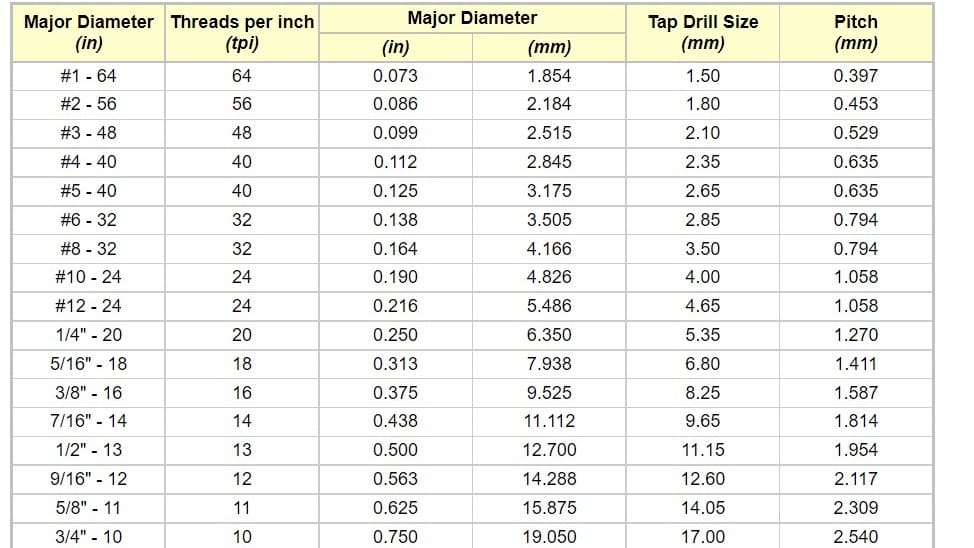
- Inch threads: Inch threads are designated using a number of standards, including the Unified Thread Standard (UTS), which primarily names standard thread sizes with numbers (e.g. #4). The two most important measurements in the UTS are the major or minor diameter in external or internal threads, respectively, and the threads per inch (TPI).
Therefore, when you want to design threaded elements, you should get the specifications of pitch, angle, and all the rest from the recommended standard tables.
Using Software Toolboxes
In many cases, it won’t be necessary to model the part from scratch. As mentioned above, many CAD programs are equipped with toolboxes of standard parts, and if the part you’re using is an existing commercial part, you may get lucky and not have to model it.
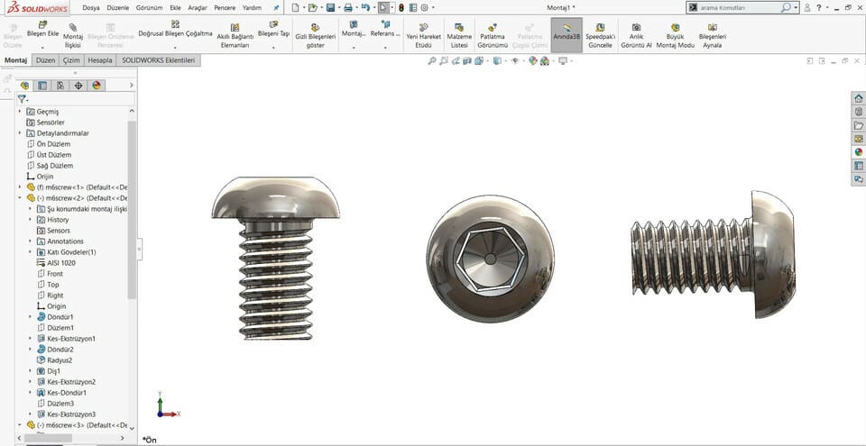
In SolidWorks, for example, you can have ready-made screws and nuts without needing to model them yourself. You also have a variety of display options:
- Simplified: The screw appears smooth, but the screwing ratio of the pitch still applies.
- Schematic: The model has a sticker of the thread.
- Detailed: The model already has a “thread” modeled into it.
Be careful, however, to check the thread is functional. In some versions of SolidWorks, for reasons only the developers know, this thread isn’t actually a spiral but is instead an array of one circular cut made in the same plane, meaning the thread isn’t actually real and won’t screw. If you print this thinking you cheat the system, you’ve actually just wasted valuable printing time. This isn’t the case for every software though, so just remember to check.
Fusion 360
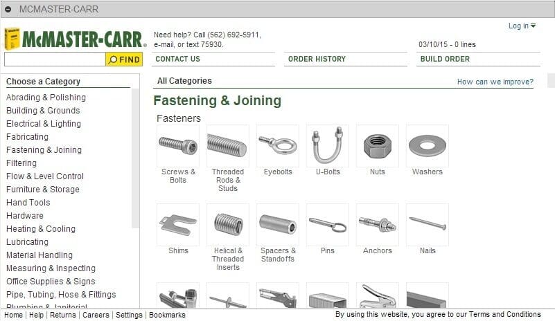
Fusion 360 relies on add-ins to increase the software functionality. When it comes to fastening elements, McMaster-Carr is the most popular. It includes elements like screws and bolts, threaded rods, washers, pins, and nails.
You can access McMaster-Carr in the Design workspace. From the Solid tab, click Insert, then “Insert McMaster-Carr Component”. Confirm by clicking “Ok”.
You can browse through the many categories or search directly for what you want in the search field. Once you select something – a screw, for example – you can choose the thread size and length, then add it to the workspace.
Modeling Threads
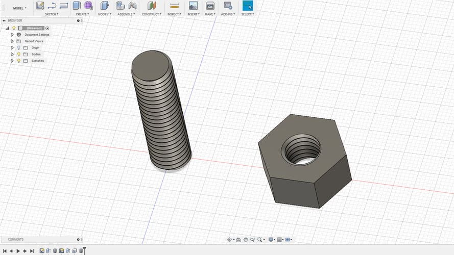
If the threaded element you need isn’t conveniently available, you’ll have to model it from scratch. Below, we’ll demonstrate the process of designing external and internal threads using Fusion 360’s simplified thread generation function.
Other CAD programs may have similar tools. As we said before, however, it is most important to understand the basics, including the terminology, established standards, and design principles – all of which we discussed above. With this knowledge, it should be possible to use any capable modeling tool to manipulate models and input values to generate the desired threads.
Let’s start with the external thread of a bolt.
External Thread
- Draw a circle with the diameter as the desired thread’s major diameter.
- Create a cylinder by extruding the circle to the desired thread’s length.
- Go to “Create” and select the “Thread” option.
- Select the cylinder you just created. Make sure that the “Modeled” checkbox is checked, then set the thread type and other thread parameters.
- Hit “OK”.
And, that’s that — you have your external thread! To make it a proper bolt, you’ll have to attach it to a head of your liking.
Now let’s design the nut with an internal thread.
Internal Thread
- Draw a hexagon. For the purposes of this tutorial, just make sure it’s bigger than the thread you want to design.
- Extrude it to the desired height.
- Make a hole in the center by selecting the “Hole” option in the “Create” menu. The hole diameter should be the thread’s major diameter.
- Select the internal surface of the hole you just created, go to “Create”, then choose the “Thread” option.
- Remember to check the “Modeled” option. Set the thread size and other parameters.
- Click “OK”.
There you go. Your first threads are ready to print!
3D Printing Threads
One way or another, we now have a completed CAD model of a threaded element, so the next step is to print it. Here’s where the fun begins. To make sure the prints are successful and have a good lifespan, let’s first look at some printing considerations.
Getting Started
One of the first things you’ll need to consider is the material you’ll be printing with, as this plays a big role in how well the printed element will work. A screw exerts a considerable vertical force along its length, which in the case of a 3D printed screw, is simply a series of bonded layers.
For weak materials like PLA, it’s possible that this force can cause the screw to snap at a critical point. Therefore, consider using stronger materials like ABS or nylon for this type of application.
With the material decided, there are a couple of important printer setup steps before you start printing threaded elements. You’ll want to make sure your printer is properly calibrated. The extruder’s calibration is important. It’s also highly recommended that you level your print bed.
Print Settings
The following are some general guidelines for setting up your print for the best possible threads:
- Depending on the aim of the print, you’ll want to either print your threads vertically or horizontally. While vertical will mean fewer supports and post-processing, if strength is the goal, a horizontal alignment will yield more resilient prints. For best results, thread axes should be perpendicular to the print bed.
- Print without supports, or at least make sure that supports don’t go inside the thread. Otherwise, it could be a real pain to remove them and preserve functionality, especially with internal threads.
- If possible, use at least four vertical layers (shells) or at least 2-mm thick vertical walls. This will ensure a strong thread.
- Infill density depends on your application, but try to set it to at least 25%.
- Layer height is an important parameter when printing threads. For smooth operation, layers should be as thin as possible. As a guide, threads larger than M12 or 1/2″ can be successfully printed with 0.2-mm layers, while smaller threads should be printed with thinner layers.
Tips
It may seem like a simple thing to do, but printing threads isn’t always easy, especially if you want small diameters.
Suppose you’re using a 0.4-mm nozzle and a 0.2-mm layer height. With this setup, the smallest pitch you’ll be able to print will likely be around 0.5 mm (give or take 0.1 mm). Such a pitch is good for an M3 thread and isn’t a big problem if you’re trying to print an internal thread in a relatively large part. That’s because your thread will have enough time to cool down while the nozzle is elsewhere.
Things get interesting if you need an external thread on a screw or a bolt, for example. In this case, there’s nowhere else for your nozzle to go, meaning you’ll probably need some extra cooling. Test your printer before you decide to print many thin external threads.
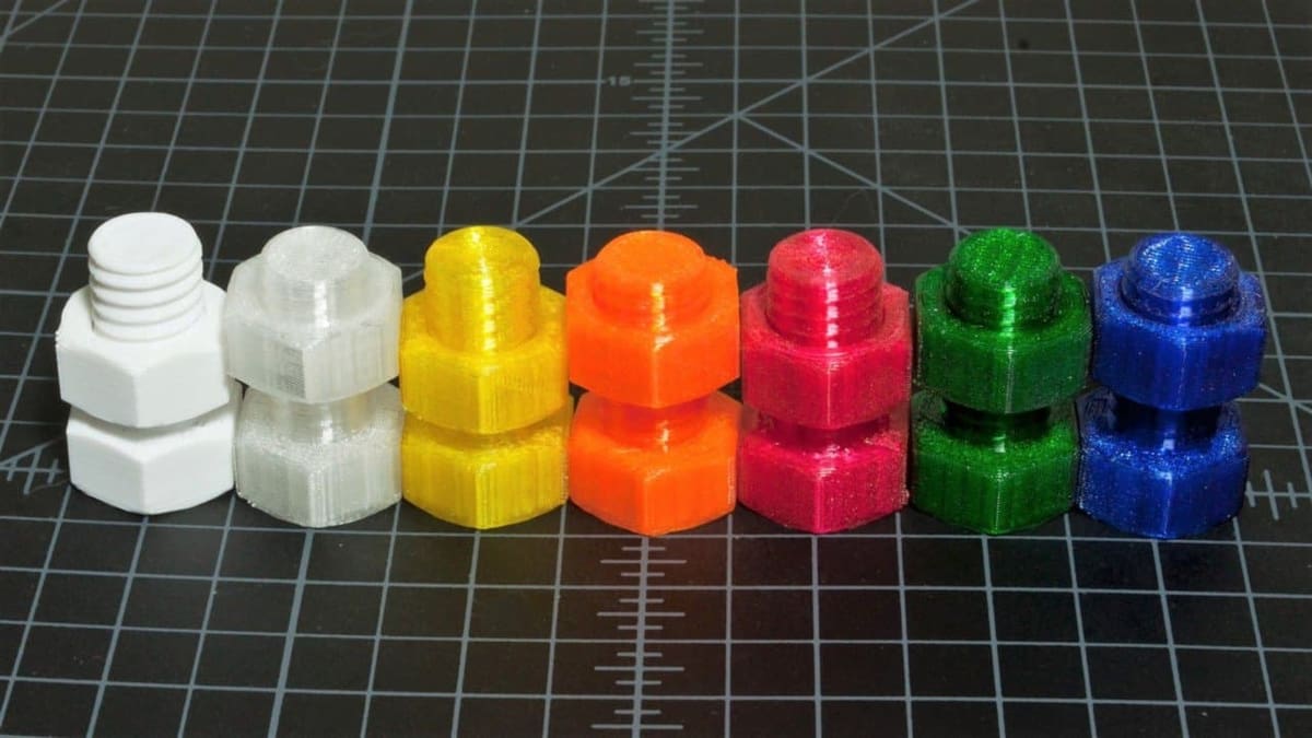
In general, it’s a good idea to try printing a thread test. This is the best way to test your 3D printer’s capabilities.
Final Thoughts
If your first test isn’t successful, don’t lose hope — sometimes it’s just part of the process. Here are some final little tips from us:
- Even if you manage to print a nice-looking external thread smaller than M6 (6 mm in diameter), think twice before using it to carry any weight. Due to its small diameter and the nature of 3D printing, this size of thread is best for visual models only. If it has to be a functional part, consider a different design.
- Internal threads smaller than 4 mm in diameter have quite a small pitch, making them difficult to print. At this size, think about printing a blank hole and cutting the thread with a tap wrench. Either way, it’s always good practice to clean a thread before use, whether it’s 3D printed or cut.
- Some materials shrink more than others. Before you start printing large parts with threads, make some small samples to check the thread dimensions. You may end up with a tight thread when printing internal threads or a very loose thread when printing external threads.
Listen to All3DP’s Podcast:
License: The text of "Threads & Screws: 3D Print Them Perfectly Every Time" by All3DP is licensed under a Creative Commons Attribution 4.0 International License.