3D Printing Strength: How to 3D Print Strong Parts

If you're going for 3D printing strength, there's more to it than strong infill. Read on to see a few key ways to get the strongest parts.
Strength in Numbers

Some applications of 3D printing require parts that can support applied mechanical loads. Most of these are “point designs”, where the part design and build process have been developed and tested through an iterative process to achieve the desired results. (For critical parts whose structural failure could cause loss of life or damage to surrounding items, always work with a licensed professional engineer to ensure that the design and manufacture of the part are safe.)
As shown in the illustration, there are many different kinds of loads that can be applied to a part. In fact, it’s common to have more than one kind of load. Combinations of loads require sophisticated stress analysis techniques to ensure understanding of stresses at all locations of a part.
In this article, we’ll explore a few ways to increase the strength of 3D printed parts, including using high-performance materials, optimal build orientation, infill density, surface finish treatments, and local strengthening. Let’s get started!
Material Choice
One of the most obvious things to do is to start by using materials that have robust mechanical properties. High-performance materials can be challenging to print on consumer-grade machines due to the high temperatures required, but there are printing services that can print challenging filament for you.
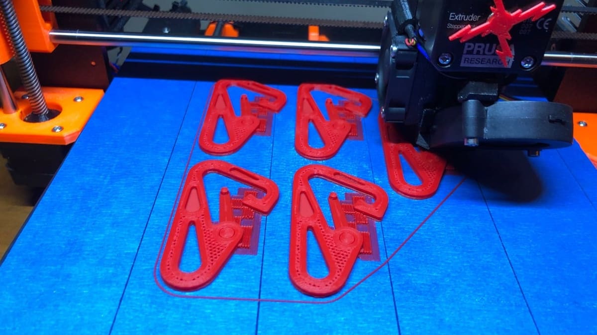
Some strong materials that are more commonly used include ABS, PETG, ASA, and nylon, as they are printable on enclosed consumer-grade printers. Most slicing software has preset settings for these materials and you can also check the manufacturer’s suggestions.
Build Orientation
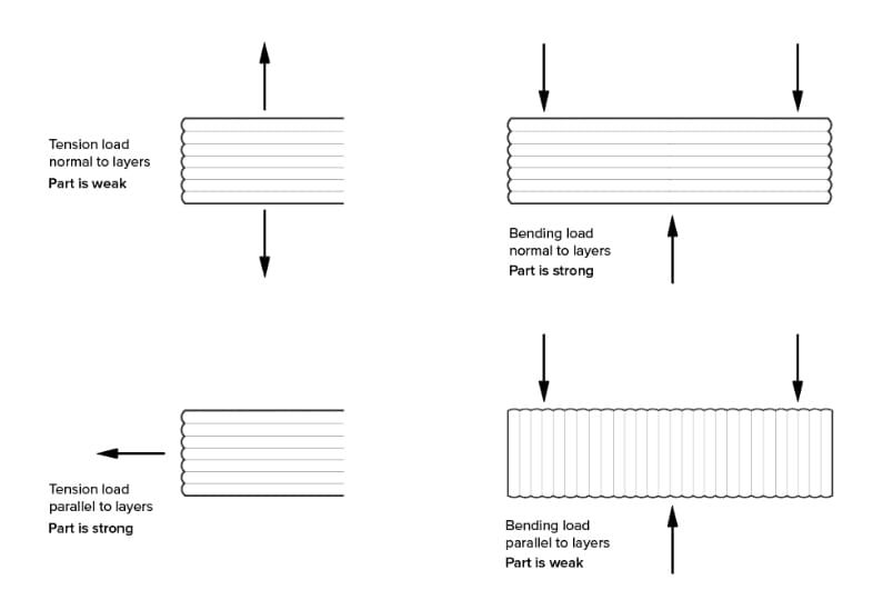
Parts printed on FDM printers have mechanical properties that are highly directional, with part strength being the weakest in the build direction. Generally speaking, it’s best to orient the part on the build plate so the direction of least stress is along the build direction.
Perimeters & Infill
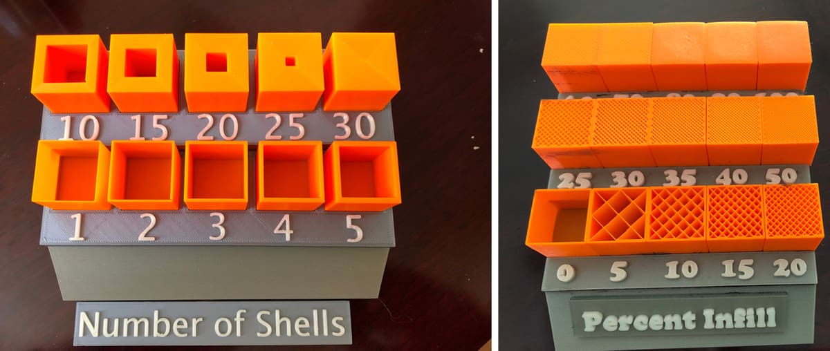
Selecting one of the many infill patterns available in your slicer depends on the use case, with different patterns providing different benefits.
Generally speaking, higher infill densities provide more strength than sparse densities. The same goes for thicker perimeters over thinner perimeters, but the effect is highly dependent on the load case. Additionally, if the surface of a printed part is going to be sanded or chemically smoothed, be sure to add enough perimeters to provide an allowance for material removal from the surface.
Post-Processing
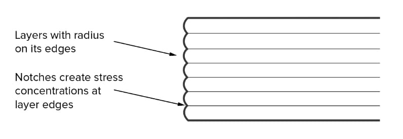
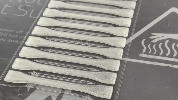
As-printed surfaces contain stress risers because of their inherent layered nature, as shown in the illustration above. These surface defects can lead to early failures, especially if the part is subject to fatigue from cyclic loading patterns.
Post-processing such as filling, sanding, and chemical smoothing can smooth these surfaces and improve part performance. Surface finish improvements should be part of the point design process for structural parts.
Local Strengthening
In this section, we’ll explore a few ways to locally strengthen parts that see mechanical stress and reinforce the part locally in the high-stress area. By making modifications to just the high-stress area, the part design maximizes the strength to weight ratio of the part, reduces filament consumption, and minimizes print times.
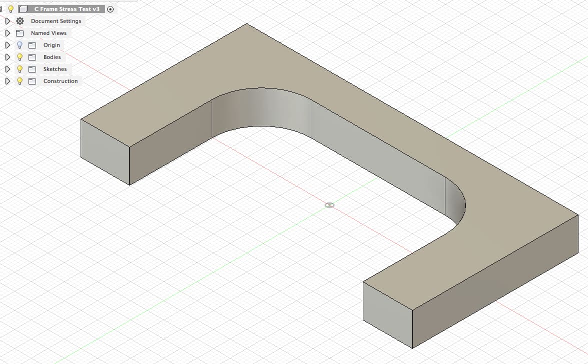
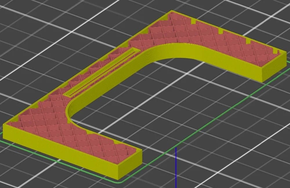
For this exercise, we’ll use a simple C-frame part. This one is 50 x 100 x 10 mm with a corner radius of 15 mm. The part was designed and analyzed in Fusion 360. Slicing instructions are based on PrusaSlicer, but other slicers will have similar settings to change.
Step 1: Stress Analysis & Preparation
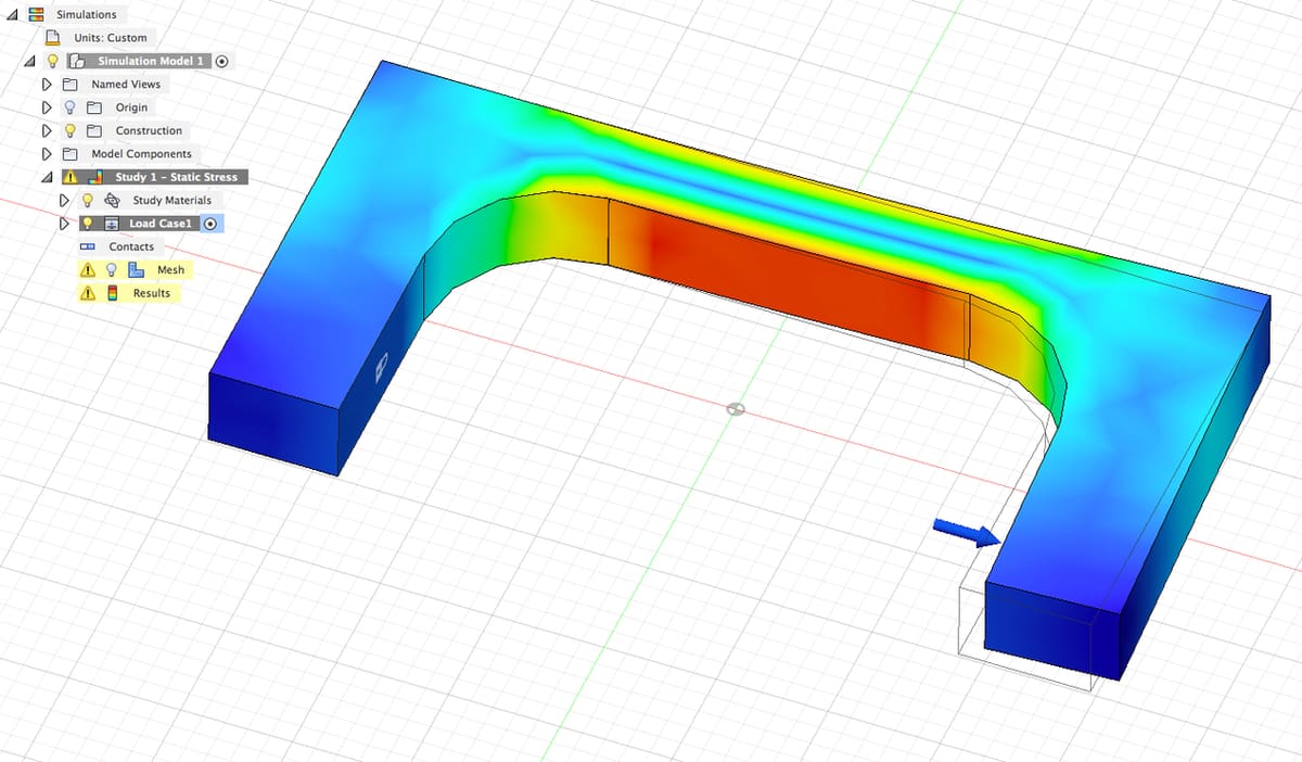
The first step in strengthening a part is to perform stress analysis, to identify the areas that need to be strengthened. Here, part material was set to 4130 steel. For loading, a fixed constraint was applied to the left side of the part, and a 1,000 lb load was added to the right side (as shown above). The red highlight indicates an area of high stress.
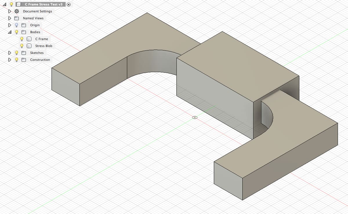
To prepare the part for local strengthening, create a box around the high-stress area, and model it as a separate body.
Step 2: Infill Density
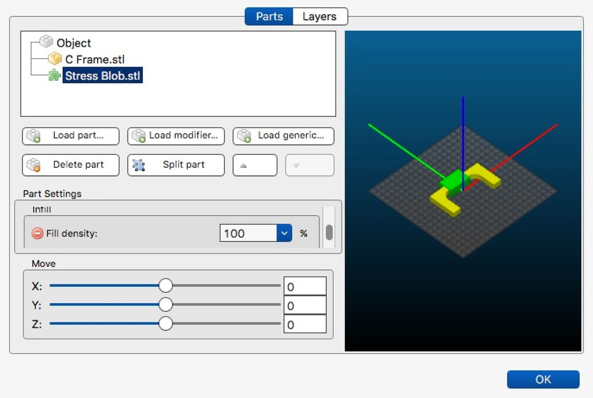
Modifying the infill density is simple. These instructions are the specific process for PrusaSlicer:
- Load the C-frame part into your slicer.
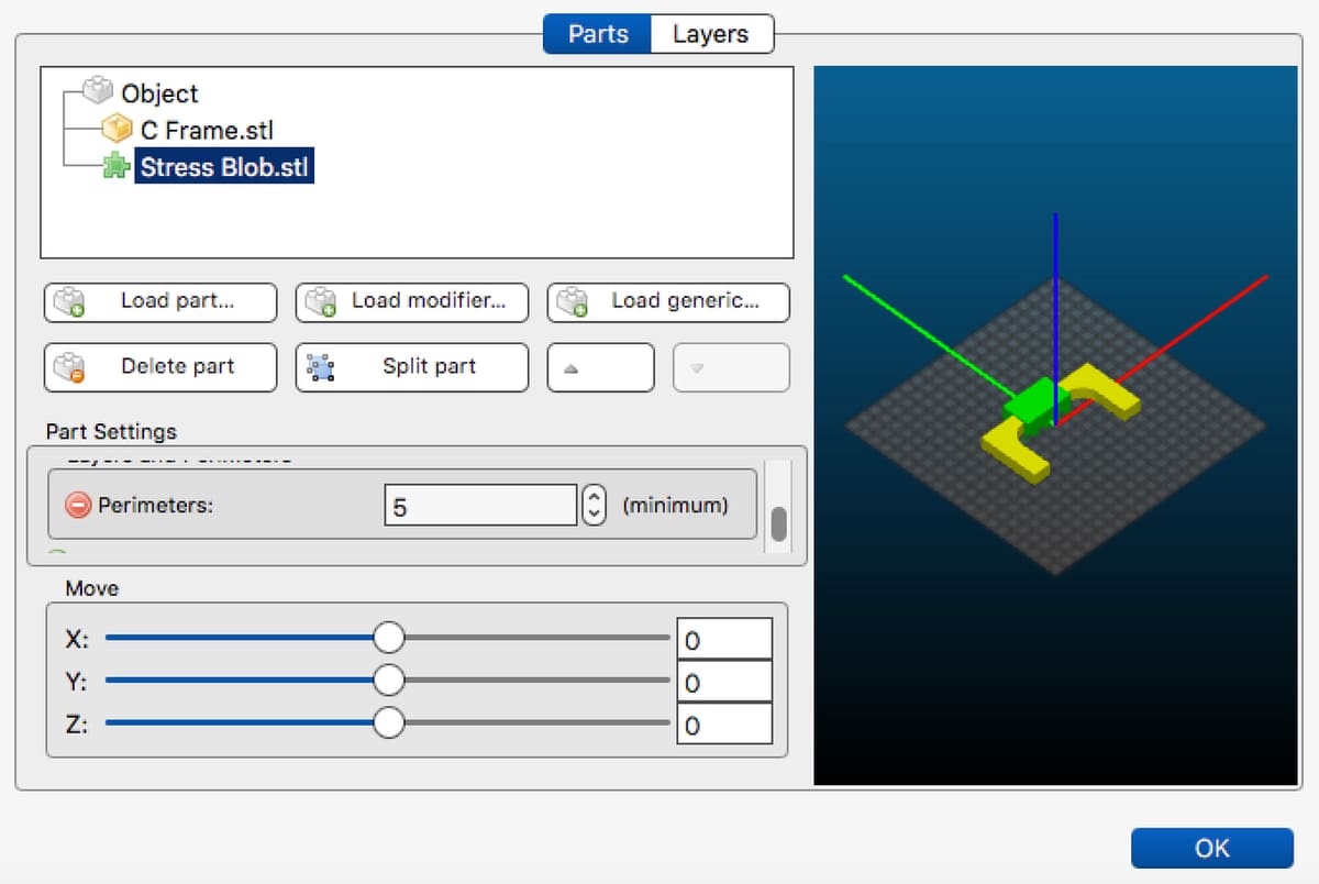
- Select the part, right-click it, and go to “Settings > Import Modifier”.
- Select the box you created that goes around the high-stress area.
- Click the green plus sign to open the infill density dialogue box.
- Set the infill density for the high-stress area to 100%.
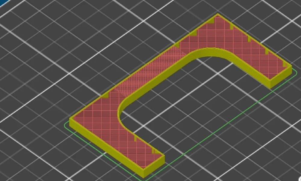
To check if you’ve been successful, perform the “Slice Now” operation. Switch to the Preview window and note the 100% infill in the highly loaded area.
Step 3: Perimeters
Modifying the perimeters of a model is also a straightforward process:
- In PrusaSlicer, right-click the C-Frame part.
- Go to Settings.
- Click the green plus sign to open the perimeters dialogue box.
- Increase the number of perimeters to your desired thickness.
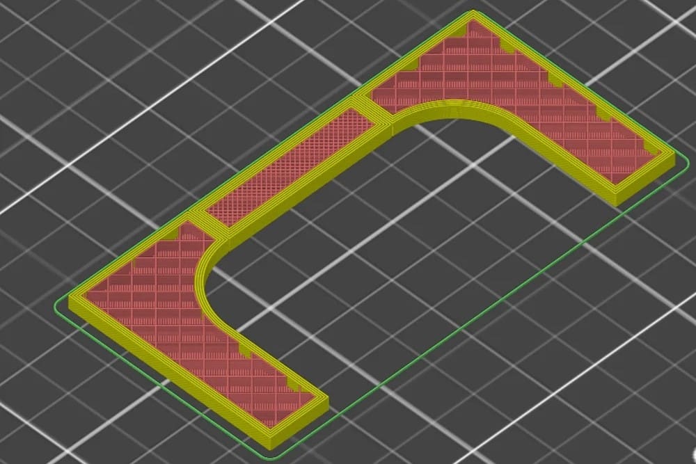
Once again, perform the “Slice Now” operation. Switch to the Preview window and note the 100% infill and the thicker perimeters in the highly loaded area.
Step 4: Internal Strengthening
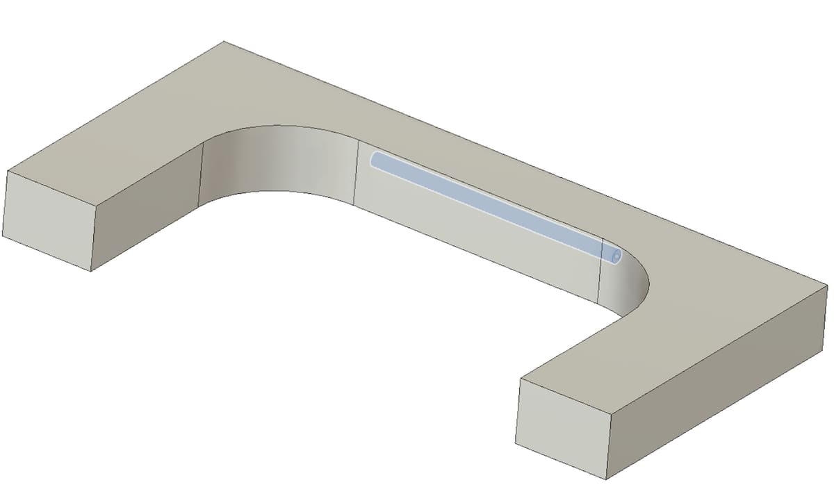
It’s also possible to add internal reinforcements. To do this, go back into your 3D model (in this case in Fusion 360), and model an internal hole in the high-stress area.
While it may seem counterintuitive to do this, when you slice the part, the slicing software will treat the hole as a part feature. As such, it’ll print it with perimeters, creating an internal rod in the body of the part.
To create an internal strengthening “rod”, perform the “Slice Now” operation in PrusaSlicer with the previous infill and perimeter settings. Switch to the Preview window and note the 100% infill, the thicker perimeters, and the internal rod in the highly loaded area.
Final Thoughts
The combination of locally increased infill density, more perimeters, and internal rods in high-stress areas increase the strength and utility of a part. This can yield a part that’s structurally robust while minimizing filament consumption and print times.
The intelligent application of all the ways you can increase the strength of a part result in prints that are suitable for their intended applications. Happy printing!
License: The text of "3D Printing Strength: How to 3D Print Strong Parts" by All3DP is licensed under a Creative Commons Attribution 4.0 International License.