3D Printing Shells: All You Need to Know

3D printing shells are more important than you might think. Read on to learn more about how they affect your model's strength and stability!
If you’re of the opinion that increasing infill is the only way to improve part strength in your fused deposition modeling (FDM) prints, you may be surprised to learn that there are several other ways to make your part stronger. These include clever geometry such as ribbed walls, post-processing methods such as vapor smoothing or, as shown by CNC Kitchen, salt annealing, or simply increasing the number of perimeters (alternatively referred to as walls or shells) included in the model.
In this article, we’ll give you the lowdown on how increasing the number of perimeters changes your print both for better and for worse. Remember, any decision in engineering or manufacturing is a trade-off, and thicker walls are no different.
We’ll start by taking a closer look at what shells are and how they can impact your print. We’ll also go over some of the most relevant settings you may find yourself tweaking.

What Is a Shell
Let’s get one thing straight first. When we say that your prints are hollow, we don’t mean that the items you’re printing are without meaning, but that they are literally full of air. You see, in order to save time, material, and part weight, most things are printed hollow or partially filled with a fractal infill.
You’ve probably noticed this already, and have likely even played around with different infill settings. What you may not realize is that the shell, the bit you see, has a greater effect on part strength than you may have anticipated. While it’s true that infill plays a role in part strength, this also depends on the infill orientation and pattern, and it may provide little or no benefit in some directions. So, if you’re looking for a sturdier print, cranking up the infill to 100% might just be a massive waste of filament if you’re not taking a close look at other settings.
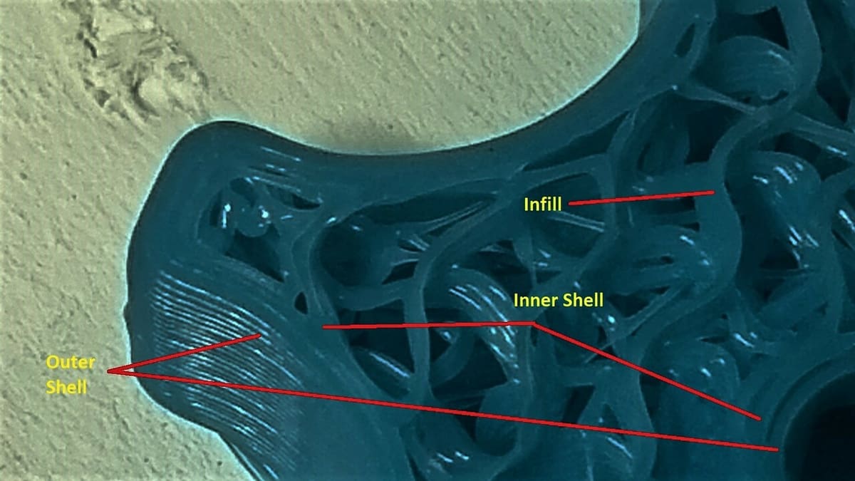
When we refer to the shell as “the bit you see”, there are technically a few layers to this (literally). A 3D print isn’t only built in layers in the Z-axis, but in all three axes. The shell is made of lines of filament usually laid down from inner to outer lines. The very outermost of those lines is the one you see (or that you sand smooth). The ones behind, known as inner shells, are backup and give a stronger structure to the outermost one.
However, it’s not just about the shell as a standalone aspect of the print. You see, to give a better structure to the print, the infill needs to be strongly connected to the shells. That bond is achieved by letting the infill lines slightly protrude into the inner shells, creating a good bond between the lines. This is part of the reason you can sometimes see the infill pattern on the outside of the print, particularly if there are very few shells or if you’re using a transparent filament.
How Shells Impact Your Print
The parts coming off your FDM 3D printer are anisotropic, meaning that they don’t provide the same strength in all directions (if they were, they’d be isotropic). This affected by a variety of things, as mentioned before. For now, we’re just going to look at the shells, or perimeters, and how these affect the prints.
In a nutshell, opting for more shells will lead to a part that’ll be stronger, heavier, and will take more time to print, and fewer shells will mean the opposite. There are a few other considerations, though.
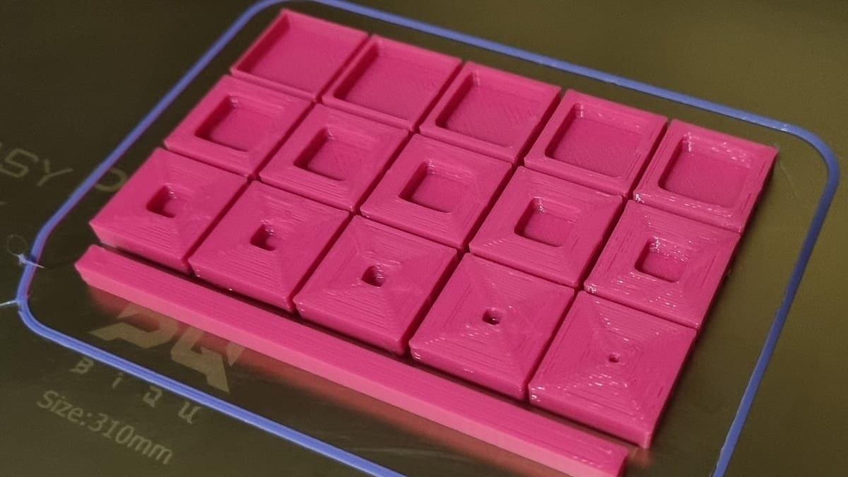
For example, if you’re going to print a large, flat model with particularly big flat walls in the Z-axis, you’ll most likely want several shells. As the part cools, the plastic will contract a little, which can cause your walls to warp (sometimes badly). Sometimes infill can compensate for this, but generally, at least two or three lines will be of greater help.
That said, if you print a large object with many walls, not only will your print take a long time, but you’ll also risk bed adhesion issues. In a nutshell, thicker walls generate more force as they contract while cooling, which can cause a significant amount of uplift at the ends of the wall. Luckily, there are several ways to combat this problem.
As we’ve mentioned, more shells will use more material and add weight to your object, and they will also take longer to print, which might increase the chance of print failure. The choice is a trade-off between ease of printing, part weight, and strength. The intended use case also needs to be considered, but a good rule of thumb is two to four walls with a 0.4-mm nozzle or one or two walls with a 0.6- or 0.8-mm nozzle. Keep in mind that two walls at 0.6 mm are equivalent to three walls at 0.4 mm.
You may have to reprint to tweak the strength of the part. Just be sure to dispose of your failed prints responsibly or recycle them!
Setting Shells
Okay, so what’s the difference between shells, perimeters, walls, and top and bottom layers? The terms are often interchangeable in the slicing software we use. Cura, PrusaSlicer, and SuperSlicer all have slightly different ways of accessing the same settings, and then you also have proprietary software like FlashPrint or IdeaMaker, as well as paid slicers like Simplify3D. Be sure to take the time to learn your specific tools if you want to see good results.
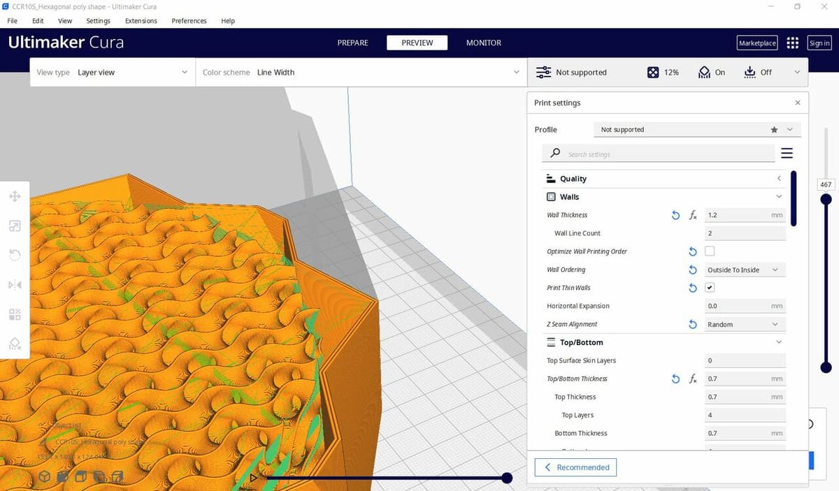
In a nutshell, “shell” means everything that’s not infill (although some slicers refer to shells and perimeters synonymously). Perimeters are, strictly speaking, the number of lines used in printing each wall. Wall thickness is the number of perimeters multiplied by the line width, so two perimeters at 0.4 mm would be a 0.8 mm wall thickness.
We should also mention that the top and bottom layers form part of the overall shell. However, they’re often referred to and controlled separately.
In Cura, for example, they can be found under “Top/Bottom > Top Thickness > Top Layers” and “Top/Bottom > Bottom Thickness > Bottom Layers”. These are the number of layers that form your top surfaces and also the number of layers directly on the build plate (or supported by support material). Decreasing your bottom layers can sometimes improve print bed adhesion by reducing contraction pressure across the bottom of the print. This is a bit hit or miss and reduces the finished part’s strength though, so we recommend perfecting your first layer instead.
Arachne
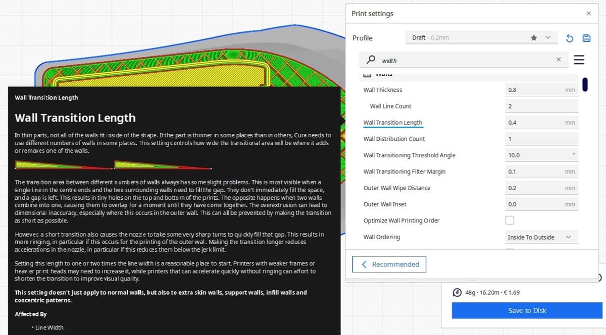
You may have seen recommendations to set your wall thickness to a multiple of your line width, and this was very true up until the introduction of the Arachne engine in the most recent versions of Cura, PrusaSlicer, and SuperSlicer.
Other newer slicers have similar functions, but if you’re not using an Arachne-enabled slicer, setting wall thickness to a multiple of line width would still be the way to go. This is because, if you don’t use a multiple on older slicers, there will be a small gap inside the walls that the printer will be unable to fill. This will cause your wall to become weaker while still using more material and taking more time. With Arachne-enabled slicers, the software simply adjusts the line width to remove any gaps.
Final Considerations
While there may be ballpark numbers to help guide you, the amount of shell-related settings can still be a bit overwhelming. Here are a few last points to keep in mind:
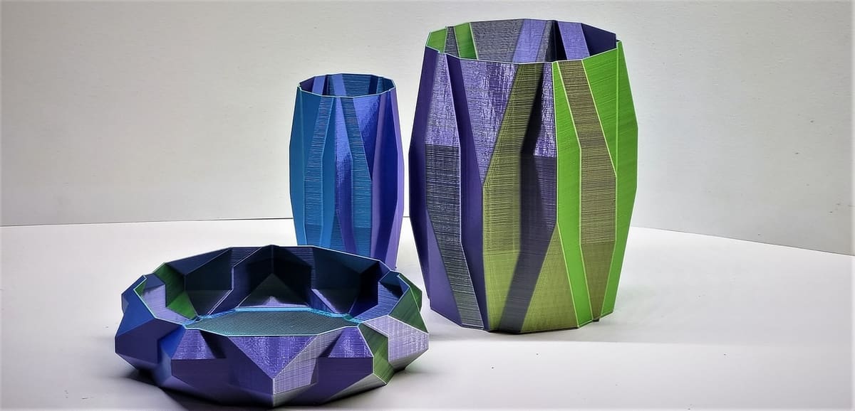
- You can’t increase the number of shells in vase mode (or “Spiralize Outer Contour”), which is where the walls are printed as a single line spiraling up from the bottom to the top of the print. This means that vase mode always has just one perimeter.
- If your model has a cavity in the middle, or a thin wall, setting more perimeters, shells, or a higher wall thickness won’t fill this in. The slicer will simply draw the number of walls that will fit within the model at the designated line thickness (with some adjustment by Arachne as discussed above).
- Different filaments have varied properties depending on the specific material, but they’re usually quite strong. You might be surprised about how much force a single wall can withstand. Do some experiments on your machine and processes to save plastic in the future!
- If you’re going to sand your print, we recommend that you use at least two – preferably four – walls. While you should be able to stop at less than one layer of removed material, the complex geometry of most prints often makes this difficult.
License: The text of "3D Printing Shells: All You Need to Know" by All3DP is licensed under a Creative Commons Attribution 4.0 International License.