3D Printer Dimensional Accuracy: How to Achieve It

When using a 3D printer, dimensional accuracy can be hard to achieve. Use these practical tips to achieve the best tolerances possible!
Dimensional accuracy, as its name implies, is an assessment of how close a given dimension is to a target value. When it comes to 3D printed parts, accuracy means how closely the physical printed component resembles the digital model. There are many concurrent factors that determine the final fidelity, present in both hardware and software. These variables should be addressed one by one in order to get to the root of the issue. It might appear daunting, as every factor determines and at the same time is influenced by something else. That’s why we’re here to help.
But first, why is dimensional accuracy important?
In fact, for many models, it’s not. If you just need something for fun or decoration, you usually won’t be pulling out the calipers to ensure a tolerance of 1 Angstrom. However, if you need precise parts to be compatible with other hardware, high dimensional accuracy is a must. In this article, we’ll go through a number of steps that should improve your FDM printer’s dimensional accuracy. The order here is quite important, so make sure to follow each section in the correct sequence. Let’s get into it!
Working Units
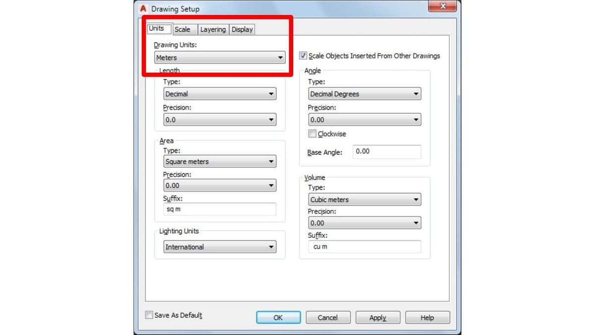
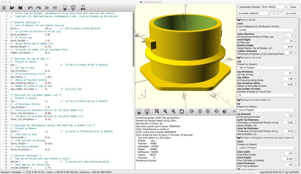
Before modifying anything on the printer or in the slicer profile, make sure that you’re working with the right units. If your 3D model is using one unit, and your slicer uses another (e.g. centimeters vs. inches), you’ll obviously notice some discouragingly large or small prints. Make sure you’re only working with one unit of measurement, and move on to the next easy fixes. Additionally, if you’re looking to scale a model to fix an improper export, double-check the scale percentage.
Check Your Printer's Accuracy
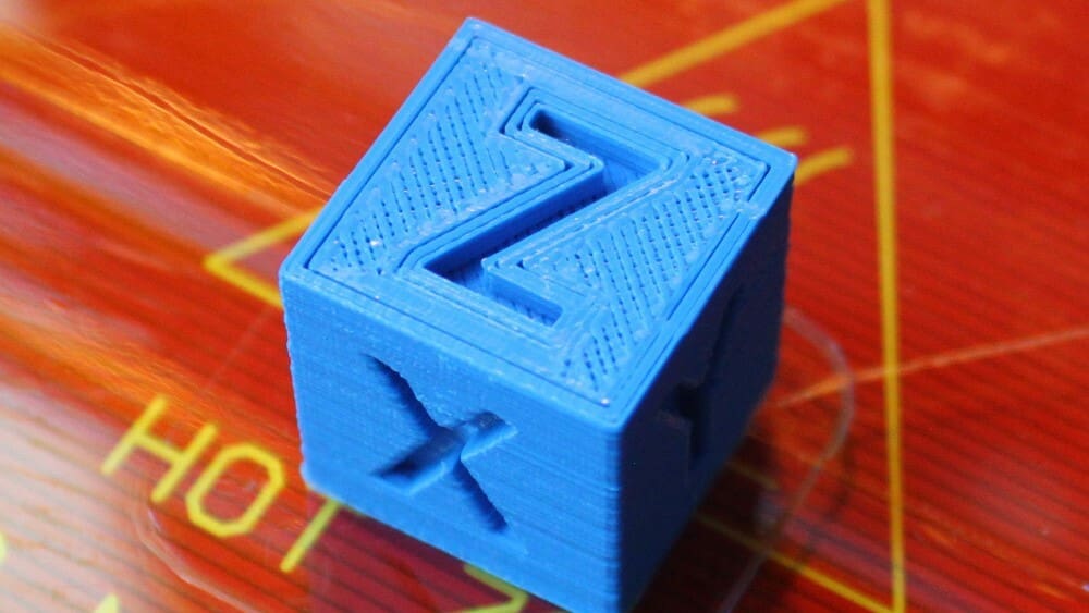
First and foremost, we must assess how accurate (or inaccurate) the printer is. A good way to start is to choose a reference print. We’ll be using the same model (even the same G-code, if possible) to compare future prints and understand how much we’ve improved. To this end, a number of helpful test prints exist out there, with calibration cubes being especially useful.
Using a specific example, Thingiverse user iDig3Dprinting’s calibration cube measures 20 mm in the X, Y, and Z directions. If you print it, you should measure the actual dimensions of your print. The difference between the actual dimensions and 20 mm will indicate the dimensional accuracy of each axis on your printer.
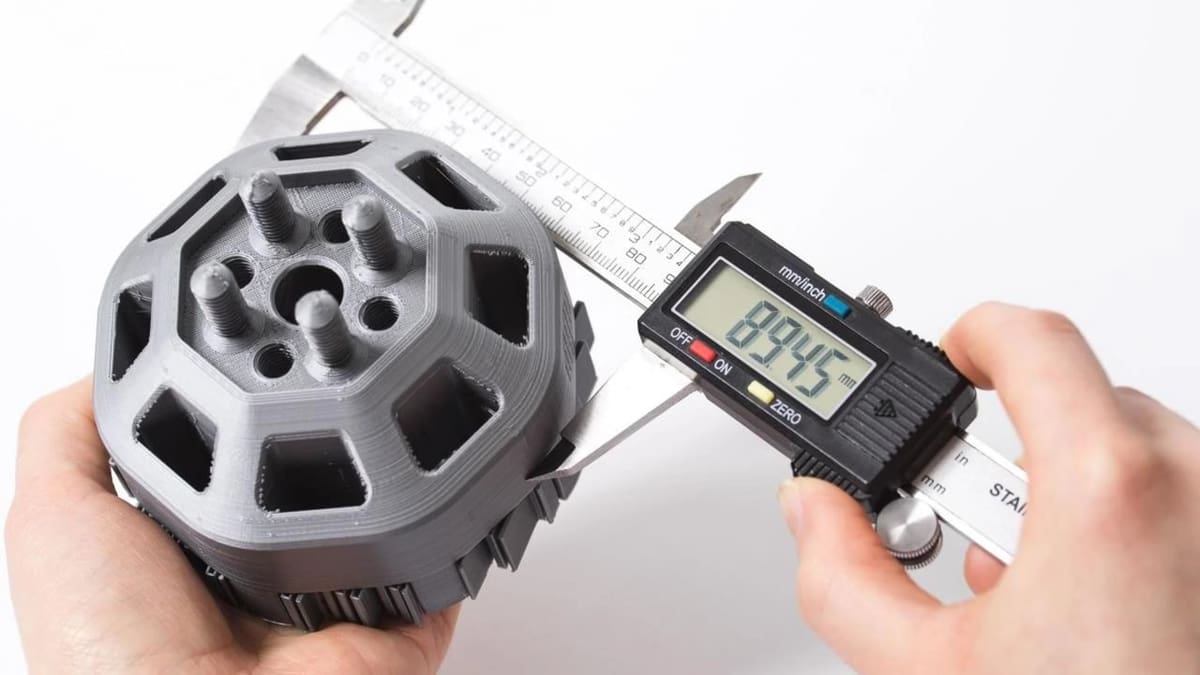
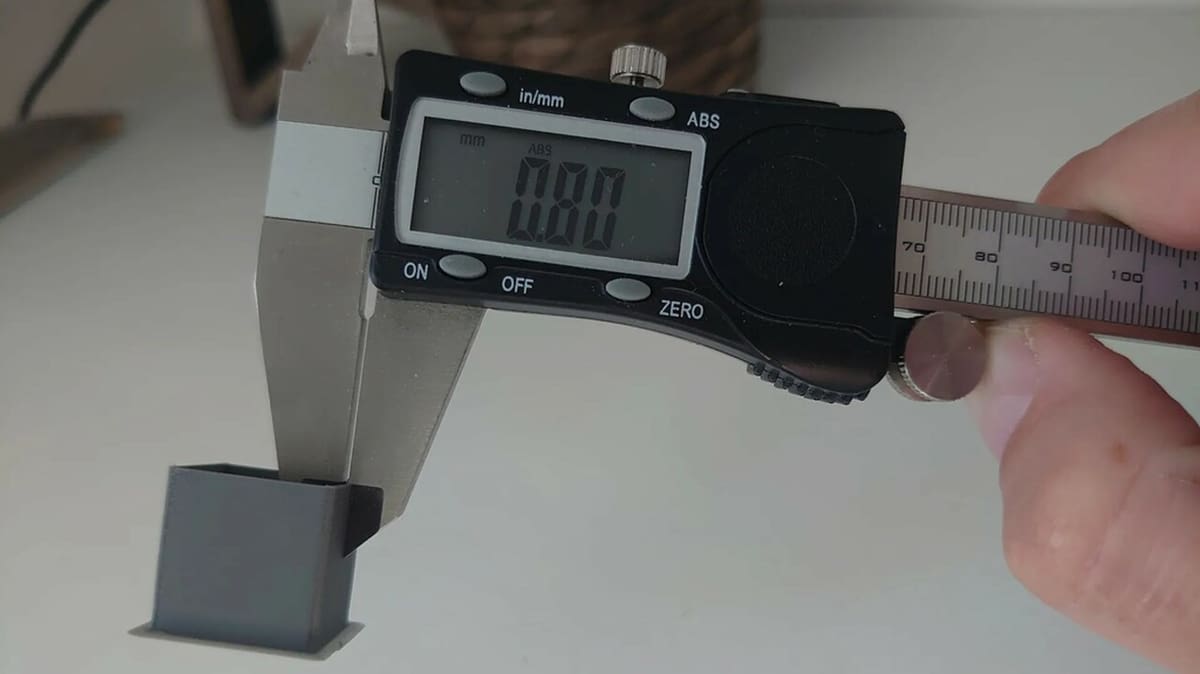
For precise measurements, it’s recommended to use a caliper. When measuring a part, remember the following:
- Use the tips of the jaw, and not the flat part, to avoid incurring “medium” values.
- Don’t squeeze the jaws. Most plastic polymers are soft enough to let the caliper dent it. This will result in inaccurate measurements.
- For each dimension, measure multiple points on the faces of the cube (or the walls of the model) and average the values. It’s insufficient to obtain only one probe per dimension.
- On a related note, consider the bulges that frequently occur at corners or layer changes, and exclude them from your calculations.
For reference, we can consider the following values for most desktop FDM machines:
- Greater than +/- 0.5 mm is bad
- Less than +/- 0.5 mm is average
- Less than +/- 0.2 mm is good
- Less than +/- 0.1 mm is fantastic
For most purposes, it’s not practical to aim for a fantastic grade, as it’s really hard to reach. Instead, aim for the level you actually need, and use the saved time and effort to work on other aspects of the printer.
Keep in mind that, most times, positive dimensional inaccuracies are better than negative ones. You can sand prints down to size, but it’s pretty hard to add material after printing!
In any case, you should now know how much of a problem your printer’s tolerance is.
Suggested Workflow: 10 Steps

Calibrations can be hard to perform and repeat due to the cascade of dependencies. The solution to this is to isolate and tune each setting or component by itself, and then verify that the whole assembly still works.
Here we have a suggested (but not mandatory) 10-step guide for troubleshooting accuracy issues. More involved steps will be explained further in later sections. This routine can (and perhaps should) be performed more than once over time, for example each time you change the material type or mechanical components.
- Print a test cube as a reference.
- Make sure that the belts are tensioned and that there are no mechanical impediments. (We’ll discuss this in the section Mechanical Components.)
- Check the hot end for any clogs or the extruder for signs of under-extrusion.
- If you haven’t already, calibrate the e-steps.
- Use a high-quality material, choose a reference temperature, and stick with it. This will minimize the number of variables influencing the results, and focus on the source of the issue.
- If available in firmware, calibrate linear advance.
- Calibrate the hot end flow. (We’ll guide you through this in the section Print Temperature and Flow Rate).
- Re-tune retractions. This step is essential after changing the flow or enabling linear advance.
- Print another test cube and compare it to the original. If you print multiple, note the settings you used and date them.
- Consider using additional settings in the slicer. This is the last step that can be performed in a routine, and it’s a sort of “last resort”. (For this, refer to the section Slicer Compensation).
It’s important that you follow the list in this order. Otherwise, some settings will override others and invalidate previous tests.
Mechanical Components
There are a lot of 3D motion systems nowadays, and that’s without counting the variants and mods available. Unfortunately, all of them get dirty, wear out, and need maintenance to work.
The following goes over how to maintain and troubleshoot mechanical issues. It’s important to mitigate (or even eliminate) these, or they’ll show up in the printed parts as artifacts.
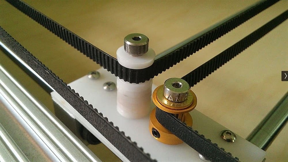
- Belts: Check the amount of wear on and tighten the belts. The latter is usually performed by pinching a belt near the idlers and feeling the springiness. If you can easily compress it to touch your fingers, tighten it. A very basic wear test can be performed by dragging a paper towel on the toothing: If it leaves a black mark, the belt should be changed.
- Belt tensioners aren’t necessarily an improvement; if they use smooth idlers instead of toothed gears, they’ll flatten the tooths on the belt over time. This will possibly lead to skipping and layer shifting.
- Don’t put too much stress on the stepper’s bearings when tensioning the belts. If at any point you can feel an increase in resistance, or that the motor is running significantly hotter, loosen them a bit.
- Screws: Tighten all the frame screws and check that none are stripped.
- Bed: Tram and level the bed.
- V-slot profiles: These can get quite dirty. A rapid clean with a general-purpose cleaner and a towel will remove the debris accumulated. If you notice excessive wear on the rollers, consider loosening the eccentric nuts to reduce the pressure. If you can feel that the carriage has a “bump” when moving it, it’s possibly a flat spot on the wheels that need to be changed.
- Rails: Remember to lubricate linear rails according to the manufacturer’s specs and timeline. Each one will recommend different procedures and materials, so stick to them.
- Rods: If your printer has linear rods, move the axis gently to check the bearings and to find any friction. Inspect the bearing for any debris or evident wear signs.
Once you’ve made sure that all mechanical components are working correctly, you can move on to the next step.
Print Temperature & Flow Rate
Since FDM printing revolves around the deposition of molten material, it’s logical that the temperature and flow rate will affect the overall process. In particular, higher temperatures usually mean a less viscous filament, which will change the flow. Lowering such values can help reduce flow overshoot, but an excessive reduction could result in under-extrusion. For this, a temperature tower is a great way to benchmark your preferred temperatures.
The slicer determines wall flow with a decent baseline accuracy, but there are some situations where it might be necessary to override that value in order to significantly improve single wall or overall slim models’ accuracies. Note that it might be required to adapt the flow on a per-material and per-model basis.
To properly calibrate the flow, the so-called Wall Cube test is maybe the most widespread. You can also find a step-by-step guide from maker and YouTuber Teaching Tech. Follow all the indications to create the cube and use the included calculator to determine the flow scaling factor to use in the slicer.
If the flow is only slightly off, it might be best not to modify this setting. It’s possible that there are other causes that are in play, such as a worn-out nozzle or poorly set e-steps.
Slicer Compensation
Once you’ve eliminated all other variables and you’re sure that nothing else can be improved, you can start modifying the G-code via the slicer.
Shrinkage
One important factor to keep in mind is that certain polymers (such as ABS, ASA, and nylon) shrink when they cool. This means that your print will be smaller in all directions by a constant factor. Filament manufacturers specify this ratio in the datasheet, and it’s usually in the 3-6% range. You can also calculate it yourself by comparing the model with the printed part. To compensate, scale your part up across all dimensions by a few percentage points. Alternatively, Cura has introduced a setting meant to do the same thing, the Scaling Factor Shrinkage Compensation. It works in a similar manner and has the same result as the scale tool.
Horizontal Geometry
Most slicers also have a setting to modify the geometry of the models on the horizontal plane. For Cura, it’s Horizontal Expansion, and for PrusaSlicer it’s XY Size Compensation. You can apply an offset in millimeters to all polygons in the XY-plane to compensate for inaccuracy. A positive value makes the object bigger, a negative one smaller. Additionally, in Cura, you can modify vertical holes in the models with the Hole Horizontal Expansion setting.
Tolerances
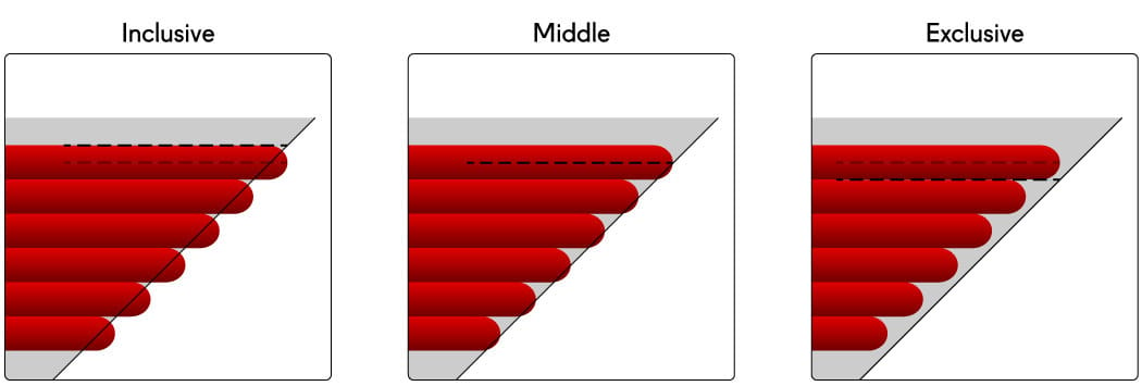
While expansion settings can work great for planar parts (such as boxes or cubic features), more organic shapes tend to be harder to compensate for. In these cases, Cura’s got your back. Under the Experimental menu, the Slicing Tolerances setting tells the slicing engine whether to put all perimeter moves inside the model (Exclusive), slightly outside (Inclusive), or right in the middle (Middle). This offers a really small level of adjustment that’s perfect for small retouches. For example, if you have two parts that have to mate together, setting the male to print as Exclusive and the female as Inclusive will yield the best results possible. For everyday slicing, the default Middle is fine.
Compensate While Designing
Even though all these fixes can improve your printer’s dimensional accuracy, you cannot expect 100% accuracy from your prints. There will always be at least a tiny inaccuracy that lingers.
If you’re designing parts to print, take the inaccuracy into account. For example, if your printer can only print down to +/- 0.1 mm, try making screw holes 0.1 mm bigger. Compensating for the dimensional inaccuracy of your printer during the design process will make your experience much smoother.
You can also scale other designers’ models to fit your machine’s tolerances. However, make sure (before you scale) that you won’t be changing any important features of the model.
Adjust Steps per Unit in the Firmware
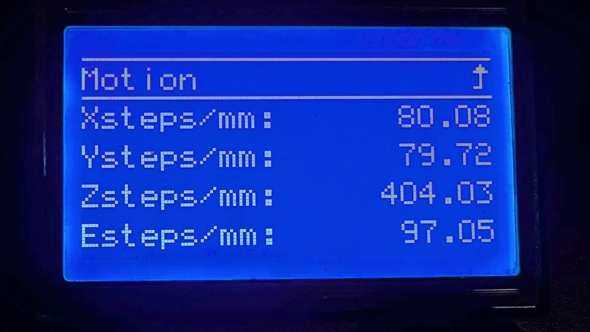
This is a “last resort solution”. If you’re experiencing significant (greater than +/- 1 mm difference) dimensional inaccuracy after checking all of the mechanical components, chances are that your printer’s firmware has the wrong steps per mm set for your axis motors.
Do not resort to this solution early in the game. Most of the time, especially with bought 3D printers, the steps per mm is set perfectly. If you’re experiencing dimensional inaccuracy and adjust this already-tuned setting, you may simply skirt around the actual problem. As a result, you might notice worse tolerances or other problems.
To properly adjust the steps per unit in your printer’s firmware, do not use the dimensions from your calibration cube. Instead, measure (as precisely as you can) how far your axes are moving when told to move a certain distance.
- Assign the variable e to the expected distance, o to observed distance, and s to current steps per mm.
- Measure e from your cube and find s in your firmware.
- Calculate: (e/o) * s
- Change the current steps per mm in your slicer with this new value.
- Repeat this for each axis.
Note: You may need to assign different steps per unit for each motor even though they’re the same kind of motor. Adjust each axis’ steps per unit based on the dimensions you measured from that axis.
This adjustment in your printer’s firmware should result in much improved dimensional accuracy. If you want a more detailed guide on this process, check out our printer calibration guide.
License: The text of "3D Printer Dimensional Accuracy: How to Achieve It" by All3DP is licensed under a Creative Commons Attribution 4.0 International License.