3D Printed Bearing: Tips & Tricks to 3D Print Your Own

Bearings are crucial components in all sorts of machines. But did you know you could 3D print them? Dig into the guide on 3D printed bearings to learn more!
A Guide to Bearings
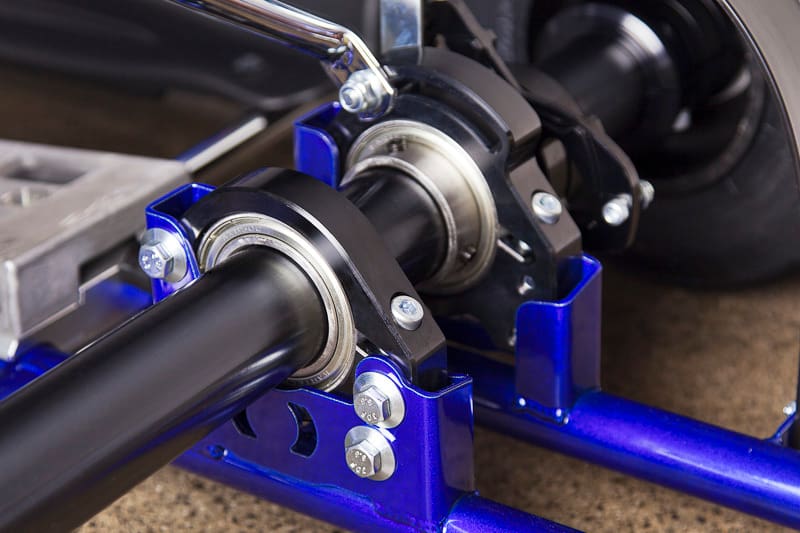
A bearing is defined as a mechanical component that constrains relative movement to the desired motion within the same axis and also reduces friction between moving parts. Bearings come in many different guises, including but not limited to the following:
- Plain bearing: Also referred to as a slide bearing, this is the simplest type of bearing comprising of just a bearing surface and no roller elements. They are the least expensive type for this reason. A plain bearing is compact, lightweight, and has a high load-carrying capacity.
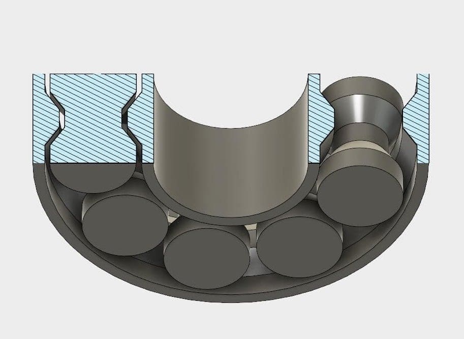
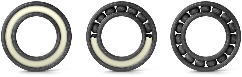
- Rolling bearing: A rolling-element bearing carries the load by placing the rolling elements (typically balls or rollers) between the inner and outer bearing rings, known as races. It’s the relative motion of the two races that causes the rolling elements to move with very little rolling resistance and sliding.
- Common types include spherical, cylindrical, tapered, and needle roller bearings.
- Ball-bearing types include angular contact, thrust, and deep groove bearings.
- Jewel bearing: A type of plain bearing in which a metal spindle turns in a jewel-lined pivot hole. The hole is typically shaped like a torus. They are used widely in mechanical watches where low friction, longevity, and dimensional accuracy are vital.
- Fluid bearing: Load in this bearing is supported by a thin layer of rapidly-moving pressurized liquid or gas between the bearing surfaces. Zero contact between the surfaces means there is also zero sliding friction, resulting in lower overall friction as well as lower wear and vibration.
- Magnetic bearing: A bearing that supports a load using magnetic levitation. Magnetic bearings support moving parts without physical contact, resulting in lower friction, zero mechanical wear, and reduced vibration.
Why Print Them?
Pros
- Geometry: 3D printing can manufacture complex shapes that would be hard to replicate in more traditional processes.
- Materials: A variety of materials can be utilized to achieve specific characteristics, including carbon-, fiber-, and ceramic-based materials as well as metals and low-friction plastics.
- Accessibility: The ability to create bearings from home, on-demand, can come in handy.
- Customization: Full customization is possible, allowing you to fit bearings to your designs rather than the other way around.
Cons
- Accuracy: Movable components of standard-sized bearings are often small in comparison to the resolution of the 3D printer, making it hard to manufacture them accurately.
- Quality: 3D printing can be a less-professional production method for bearings, which makes diameters much harder to control, especially when using fused deposition modeling.
What About Plastic?
There are many reasons for using plastic rather than metal for your bearings. Plastics require no external lubrication, are corrosion resistant (when used with glass or plastic balls), and operate quietly. They’re also non-magnetic, lightweight, and cheaper compared to metal.
Although 3D printed bearings are primarily being used by individuals looking for niche workarounds to industrial bearings, steps have been taken to introduce them to industrial applications. Acetal (POM) represents a low-friction plastic, and manufacturer Igus produces a range of practical materials.
Get It Done Right
If you don’t have the resources to print your own bearings, or if you require a material or level of accuracy outside your reach, consider reaching out to a 3D printing service. With Craftcloud, you can easily find the right provider and price for your needs. Benefit from a global network, a wide range of materials, and round-the-clock support.
Terms and Definitions
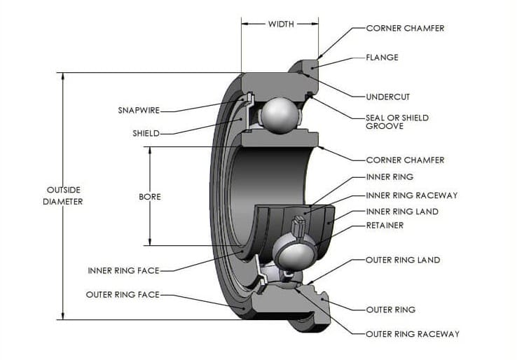
Listed below are some important terms related to bearing design and operation:
- Bearing life: The amount of time a bearing will perform in a specified operation before failure. Generally, engineers will refer to the L-10 life, which is the life that 90% of all the bearings exposed to the exact same loading and environmental conditions will reach before failing in fatigue. Factors affecting bearing life are temperature, lubrication, mounting, alignment, deformation, and contamination.
- Internal bearing clearance: Clearance is necessary so that the rollers have room to turn without building up excessive heat and friction during operation. The amount the inner race moves as opposed to the outer race under a given radial or thrust load is called bearing clearance. This can be measured by how much space there is between the internal parts during operation. For the best performance under radial loads, ball bearings should have minimal clearance. This is because the groove in both races of a ball bearing is designed to provide ample clearance.
- Cage clearance: For tapered roller bearings, there should be enough clearance in the housing for the cage. If the cage rubs against the housing it can cause the rollers to drag, and if the clearance is not sufficient, the cage may become distorted and worn. This would result in the misalignment and slanting of rollers, facilitating premature bearing failure.
- Alignment: The shaft and housing must be properly aligned. Misalignment will reduce the capacity and life of the bearing proportionately to the amount of misalignment. When the bearing is misaligned, the rollers will not carry the load along its entire length. They will carry the load, but only on a small portion near or at the ends of the rollers. This causes a concentration of load in a small area on the inner and outer race, which could result in chipping and early bearing failure.
- Operating temperature: Type of load, shaft speed, and amount of friction all contribute to one of the most critical conditions for operation: temperature. Each component of the bearing must be constructed from materials that can not only handle the load but also accommodate temperature fluctuations. But not all heat is due to the environment. The bearings themselves may cause excessive heat because of
- too heavy a load, resulting in deformed races and rollers
- friction between the rolling elements, retainer, and races
- excessive churning, from too much lubricant
- surface friction, from too little lubricant
- Lubrication: Using the right type and amount of lubricant for the job is another factor critical to bearing performance. Whenever bearing use causes excess friction, heat rises accordingly. Regular lubrication helps relieve the heat that results from bearing friction
Tip 1: Consider Your Application
Here are the key steps to matching your bearing type to be 3D printed with your specific application:
- Confirm operating conditions and environment. This includes the function and construction of components to house bearings as well as rotational speed, vibration and shock load, bearing ambient temperature, temperature rise within the system and general operating environment.
- Select bearing type and configuration. This includes mounting location, load direction, and load magnitude. Check online CAD libraries for existing designs before you make your own, as this could eliminate the need for your own prototyping.
- Select bearing dimensions. These will be based around your shaft design, taking into account any limitations your personal 3D printer has. The correct sizing of a channel when printing a ball bearing is also vital in order to have a tight running bearing.
- Select bearing tolerances. FDM printers tend to print holes under size, so you will need to increase the diameter of the internal hole slightly based on tolerance values given by your 3D printer manufacturer.
Key types of printable bearings to help with your selection in Step 2 include the following:
- Tapered roller bearing: Radial and axial loads, used in gearboxes, bevel-gear transmissions, lathe spindles, etc.
- Thrust ball bearing: Only thrust loads, only used for heavy axial loads and low speeds.
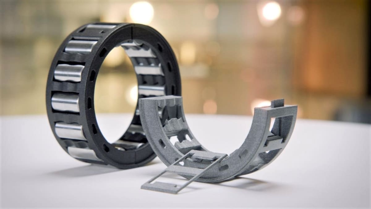
- Needle roller bearing: Use small-diameter rollers for radial load at low speeds and oscillating motion. Lightweight and occupy small space, used in the aircraft industry, bench drill spindles, etc.
- Slewing ring bearing: High axial loads supporting heavy but slow oscillating loads such as the horizontal platform of a crane, a swing yarder, or the wind-facing platform of a horizontal-axis windmill.
Tip 2: Plan Design and Printing
Designing
- Consider print-in-place bearings: This is a useful way of minimizing material usage and printing time. Each bearing ball has a shaft connected to the print bed, which allows for a one-piece print. In this instance, it would be advantageous to include small slots to break free each bearing post-print using a small screwdriver. Check out an example print-in-place bearing for guidance.
- Revolve is your friend: The revolve feature available in most common CAD tools is immensely useful when modeling bearings. In addition, having each component of the bearing in the same “part” can be useful.
Printing
- Test your circles: Testing your printer to see how successfully circular objects are printed is the most important step in planning your 3D prints. It may be optimal to print bearings “upright” using either breakable or soluble support (if possible) to achieve an accurate circular object and not an approximation, especially in the case of FDM printing.
- Bigger is better (for part accuracy): This applies for both accuracy and strength of parts, but bear in mind that larger prints take longer to complete.
- Start small (with clearances): Clearances can take time to get right. It’s best to start with a slightly tighter design and work your way bigger from there.
- Consider soluble materials: The option to use soluble support material is useful for printing bearings in place.
Tip 3: Select the Right Material
There are a wide variety of materials that can be tested and used to great effect for your 3D printed bearings. It’s first worth understanding some of the key properties and functions that will help you to filter out which materials will be suitable for your application:
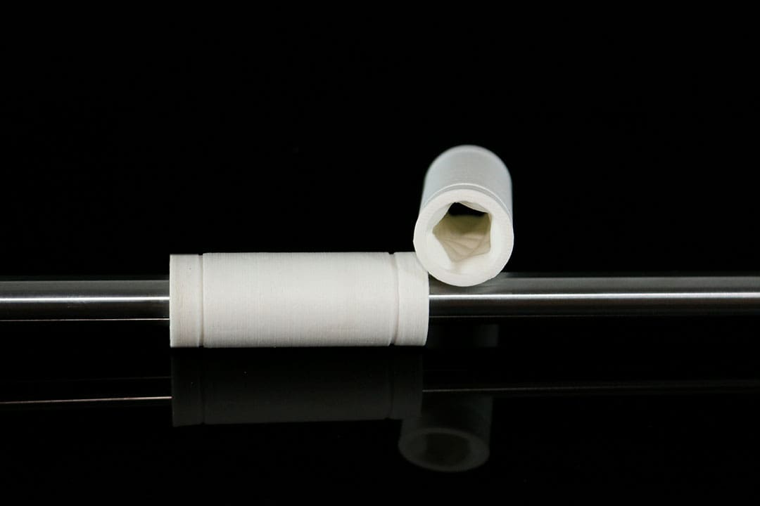
- Nylon: Key characteristics include durability, strength, flexibility, and low friction, making it versatile for all different types of bearings.
- Acetal: Also known as polyoxymethylene (POM), this is traditionally used in machined plastic bearings due to its high stiffness, low friction, dimensional stability, and excellent wear-resistance.
- Igus Iglidur: As mentioned before, Igus provides multiple 3D printer filaments with a range of properties (low coefficient of friction, abrasion-resistant, chemical-resistant, temperature-resistance) to suit differing applications.
- PLA: For testing design geometry under no load, PLA makes the most sense.
- PVA or HIPS (soluble support): PVA and HIPS soluble support allows for the alternative option of a fully enclosed 3D print of bearings. Testing will be needed in this case to determine if your design and material combination will suit soluble support.
Note that plastic bearings will not be as strong as traditional steel bearings. Consult your material supplier for technical datasheets to determine if the desired material will withstand the loads required from the bearing within the operating system.
In addition, check out some great ways you can post-process your 3D prints to remove support material, sand, protect, and finish your bearings. Metal plating could be useful in this instance, as the metal shell will increase the strength of the 3D printed part. It’s also a very thin surface coating, so your original tolerances should still hold.
Useful Tools and Models
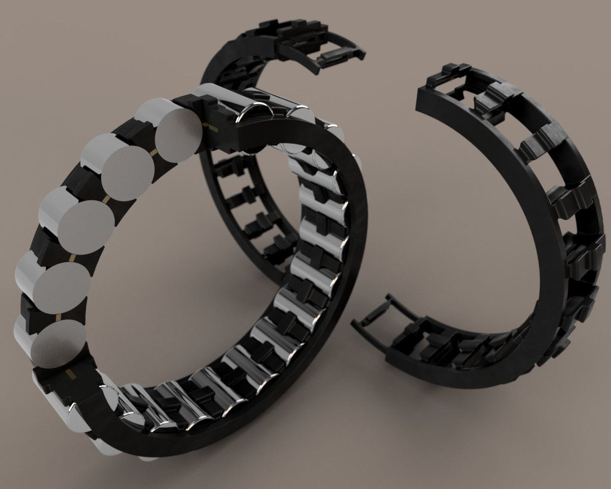
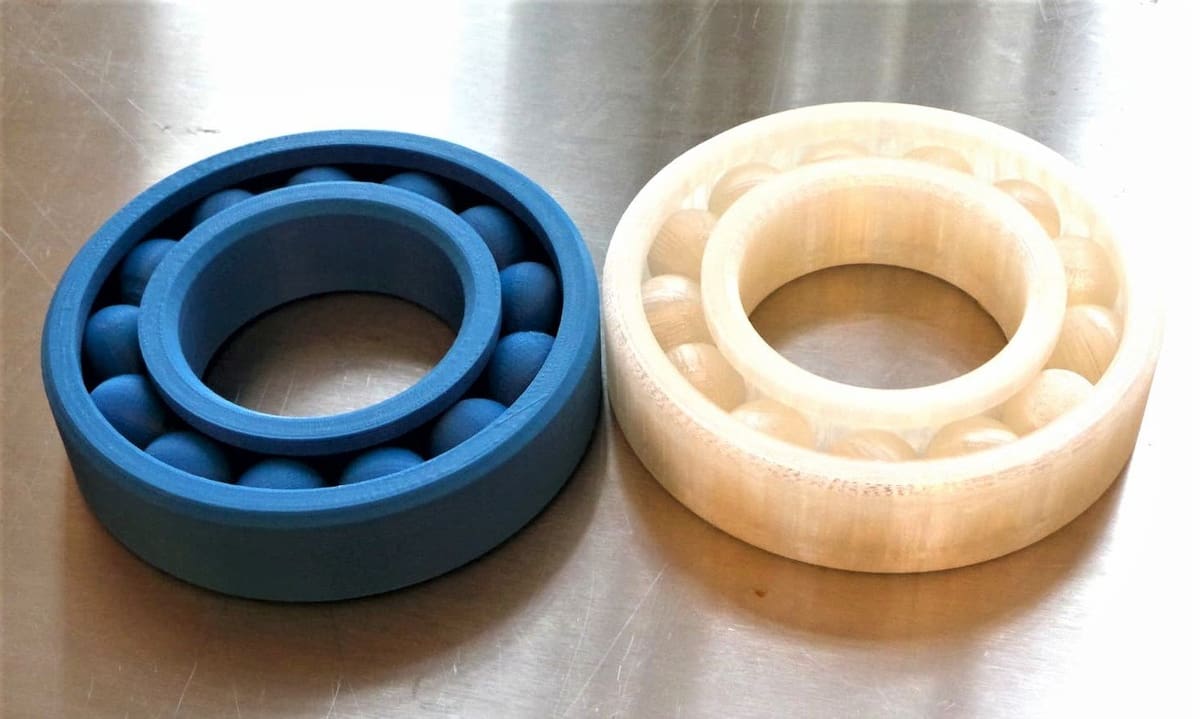
Take a look at some current bearing designs, with a mixture of caged “print-in-place” bearings and also bearings designed around existing ball bearings in metal:
Also check out this great guide for calculating axial and radial forces for a deep groove ball bearing. Note that this should be used as a guide only and not as your definitive calculation for selection.
With great strides in material and process technologies, the future is looking bright for the partnership between additive manufacture and bearings!
(Lead image source: DIY 3D Printing)