Tinkercad Tutorial: 5 Simple Steps to Success

Follow along with this Tinkercad tutorial for beginners to learn how to use Tinkercad in just five simple steps.
Tinkercad is probably one of the simplest and most intuitive 3D modeling tools available. It’s free, runs in your web browser, and has a clear user interface and intuitive building process that makes it the go-to program for many beginners.
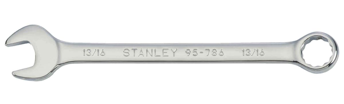
In this article, we’ll cover the basics of designing in Tinkercad by creating a simple wrench. This should be a familiar tool with a modest shape that can easily be 3D printed later on. By following this tutorial, you should be able to learn the basic functionality and tools that Tinkercad has to offer.
Of course, once you’re comfortable, you can look into more advanced projects. But first things first.
Getting Started
As a web-based application, all that’s necessary to get started with Tinkercad is to sign up for a free account on their website.
At the end of this process, you’ll be welcomed by the Tinkercad tutorial screen. Skip this for now by closing it and instead go to the home page and click “Create new design”.
The Main Interface
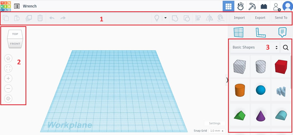
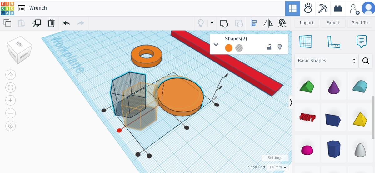
This is what a project’s main interface looks like. As you would expect, the very center is the “Workplane”, upon which models are created and manipulated. The interface is also composed of the following:
- Top toolbar, with more general tools like “Copy”, “Paste”, and “Delete” on the left and design operations like “Group” and “Align” on the right.
- Navigation tools for basic orientation like zoom in and out. Note that these specific tools can also be used via mouse wheel.
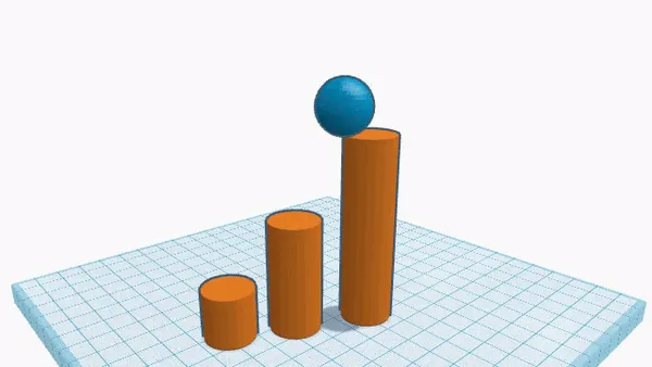
- Shape Panel, containing all building blocks for designing, including basic shapes like cubes, spheres, and text. (This can be a fun box to explore, as it has many interesting and sometimes customizable options!)
Divide & Conquer
Now that we’re familiar with Tinkercad’s interface, let’s dive right into the design.
“Divide and conquer” is a key principle in 3D modeling. Basically, it tells us to break a part down into smaller shapes and tackle them individually. These parts will then be assembled together to create the final object.
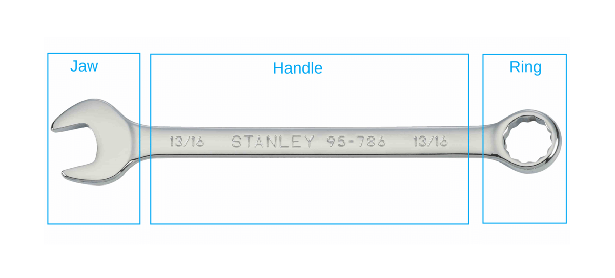
This technique comes in handy when modeling complex real-world objects. For our wrench model, let’s divide it into three basic units: the ring, the handle, and the jaw.
These units will be designed in the next three steps, and after that, they’ll be stitched together. In the fifth and final step, we’ll add some text to the wrench so that its size can be quickly identified.
Step 1: Designing the Ring
The ring of a wrench can be approximated by a solid disk with a hollow circular area in the middle, like a very thick washer.
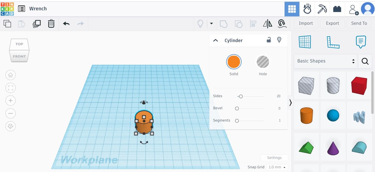
To create this shape, we’ll first drag a cylinder from the “Basic Shapes” panel to the workplane. Clicking on the shape presents its options under a “Cylinder” box that appears under the top toolbar. We won’t get into these now, but it can be fun and useful to explore features like “Bevel”.
While selected, you’ll notice the cylinder has five white squares, or “handles”, four of which are on the shape’s bottom plane and one of which is above the cylinder.
Adjusting Dimensions
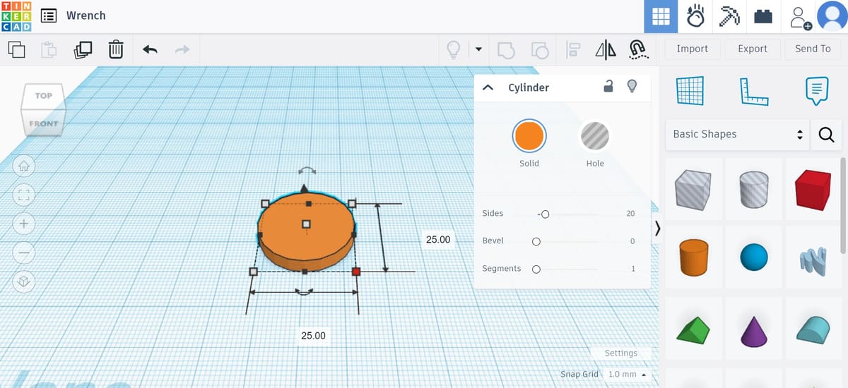
The four handles in the bottom plane can be used for adjusting the cylinder’s length and width. We want our ring to have a diameter of 25 mm. Once you click on a white square handle, a small box with the current dimensions is displayed.
Either drag the handles till the cylinder has a length and width of 25 mm or enter the values by clicking on the dimension box and hitting Enter. (By default, Tinkercad will snap any dragging to whatever value appears at the bottom right, e.g. “1 mm”.)
The handle above the cylinder adjusts its height. We want our wrench to have a height of 4 mm, so adjust it in the same way as you did with the length and the width.
Boolean Operations & Holes
We’re making progress. The solid disk is done, now we just need the hole in the middle.
Tinkercad operates on the principle of Boolean design, which allows the subtraction of objects to create empty areas and the addition of objects to form new shapes. (Note that these terms aren’t explicitly used.)
There are two ways to do this, and it’ll basically depend on which shape you want to subtract from another. Tinkercad includes by default a subtraction box and cylinder (the two first options in the Shapes panel). Alternatively, you can select any shape and simply change its format to become a “Hole” rather than a “Solid” in the pop-up menu that appears when it’s added to the workplane.
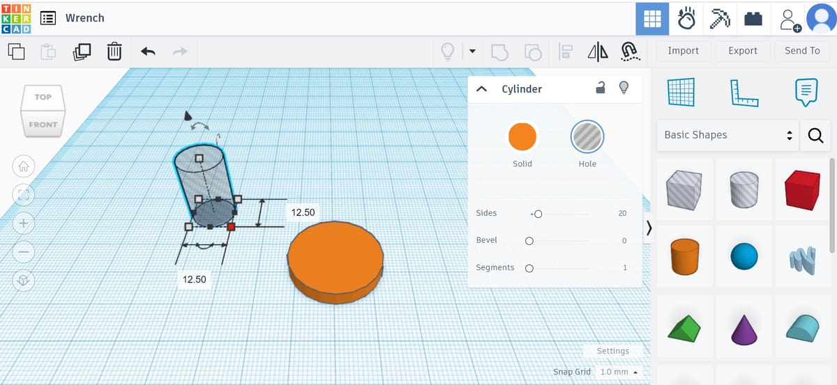
For this step, we’ll use the subtraction operation to create the circular hole in our ring. First, locate the cylinder in the Basic Shapes panel that is shaded gray and drag it into the workplane. The gray shading indicates negative space and tells Tinkercad to treat this shape as something to be subtracted.
Adjust both its length and width to 12.5 mm, which is the diameter of the hole we want.
Aligning
Next, we need to position the cylinder-shaped hole in the middle of the solid disk. For this, we’ll use the alignment tool in the top toolbar.
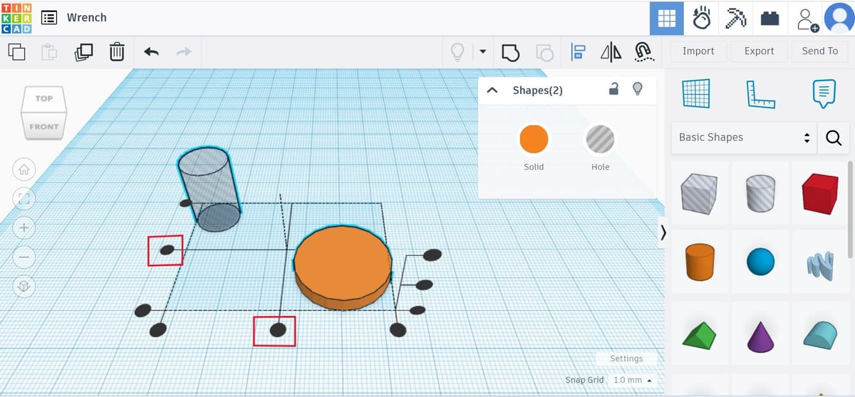
First, we need to select the objects that need to be aligned. Left-click the solid disk and, pressing Shift, left-click the cylinder hole. If you do this correctly, both objects should be simultaneously selected and highlighted.
Press the “Align” button in the top toolbar. You’ll note that black round handles will show up on the workplane. Click on the bottom middle handles, as shown above, to align the objects along their central axes in both the X and Y directions.
To exit the Align tool, simply press the “Align” button again.
Grouping

Once the two shapes are aligned, press the “Group” button in the top toolbar. This tool joins two shapes together, but in the case of one shape being a hole, it removes material. If all went well, you’ll see that only one shape will remain and the finished ring is ready.
The Ring
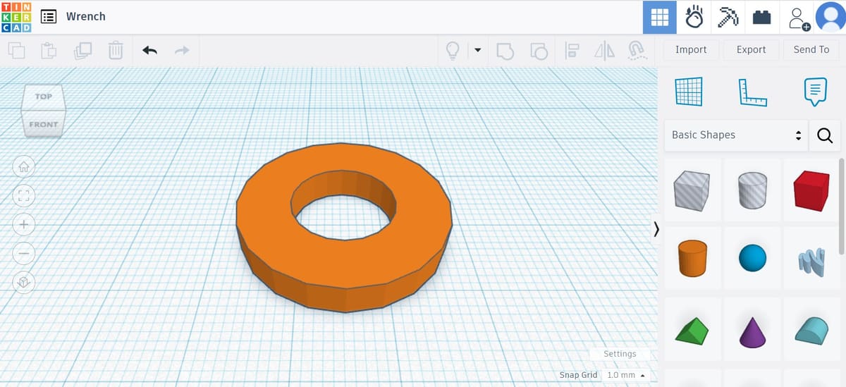
In the image above, you can see what the ring should look like.
We’ve learned quite a bit in this section. For example, we now know how to dimension basic shapes, create holes, align objects, and finally, how to group (or merge) shapes together. These skills constitute 90% of everything required to design 3D objects in Tinkercad.
You’ll see that the next steps will involve the same or similar skills. So, let’s push through!
Step 2: Designing the Handle
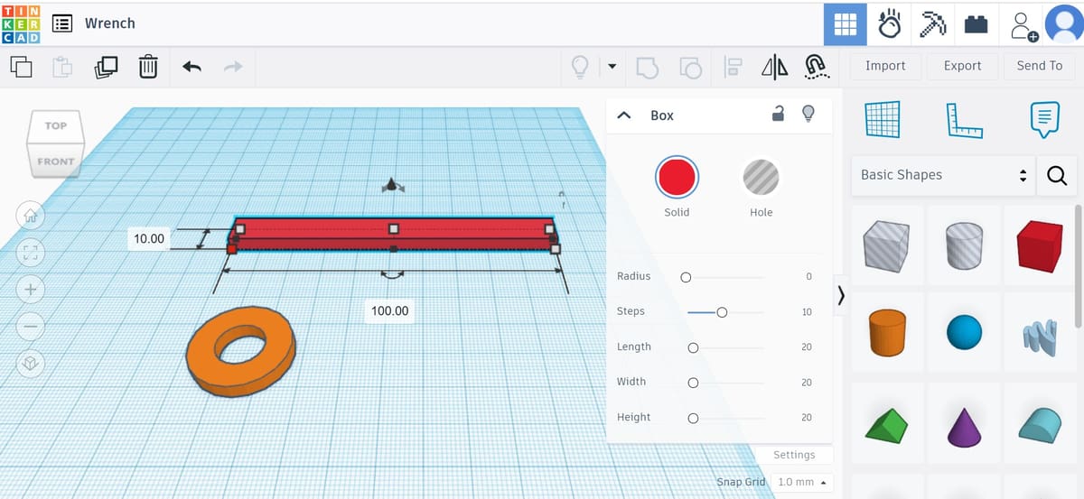
The handle is probably the easiest part of our wrench. We basically just need a rectangle with the right dimensions.
Start off by dragging and dropping a Box from the basic shapes panel into the workplane.
Set the length of the box to 100 mm and the width to 10 mm using the procedure described earlier. Then, set the height to 4 mm so that it matches the ring.
And that’s it! The handle is ready to go.
Step 3: Designing the Jaw
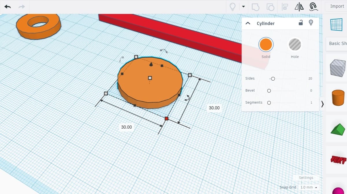
We’re almost there – just one more part to go! When considering the jaw, you might realize that designing it should be very similar to designing the ring. At least at first…
The jaw is also a circular disk, but this time with a hexagonal hole carved out at an angle. Set your disk’s diameter to 30 mm and its height to 4 mm.
Polygons & Hexagons
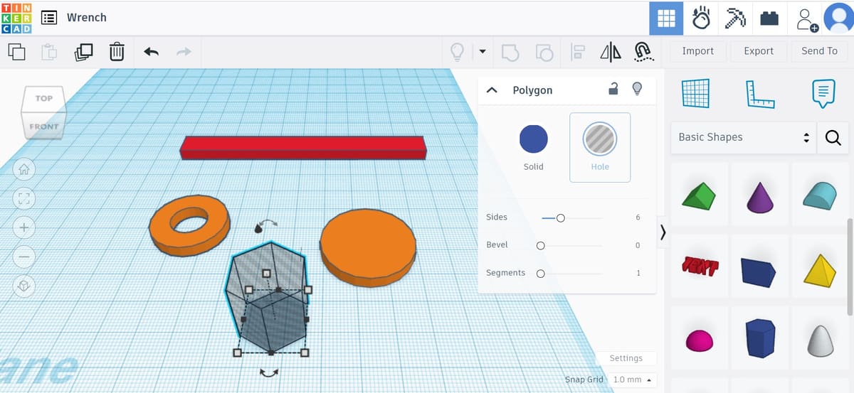
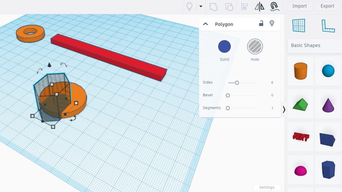
To create the jaw-like shape, we’ll use the “Polygon” basic shape.
Dragging the polygon to the workplane, you’ll see that it’s by default a hexagon shape. This is exactly what we need, but know that we could change the polygon’s number of sides by adjusting the corresponding option in the Polygon window.
For now, all we need to do is turn our hexagon into a hole. In the Polygon window, select the “Hole” option to transform this solid into negative space.
Adjusting & Aligning
Now, to set the dimensions of the hexagon. We’ll create a 15 mm wrench, but feel free to play around with it and go for whatever size you want. (Note that the rest of the wrench may not be appropriately dimensioned for values too far from 15 mm.) You only need to set the length and width here.
Let’s then use the align tool once more to position the hexagon along one of the disk’s central axes. (In other words, center it in one but not two directions.) Select both shapes, hit the “Align” button, and click on the black round handle as shown above.
Grouping
With both shapes now properly positioned, we can create the final jaw geometry.
Both shapes should still be separated, so we need to place the hexagon inside the disk. To keep the alignment we just made, hold Shift and drag the hexagon to be partially inside the disk. The hexagon should move in a straight line.
It’s time to do some subtraction magic! Select both the hexagon hole and the disk and press the “Group” button in the top menu. There you have it. Congratulations!
The Jaw
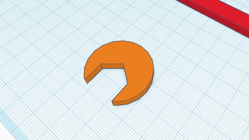
You can see in the image above that this is what the jaw should look like. As mentioned, depending on the type of wrench you’re designing, you may have opted to add more sides to the hexagon, which would yield a slightly different creation.
Now that we’ve got the ring, handle, and jaw, it’s time to finally put it all together.
Step 4: Putting It All Together
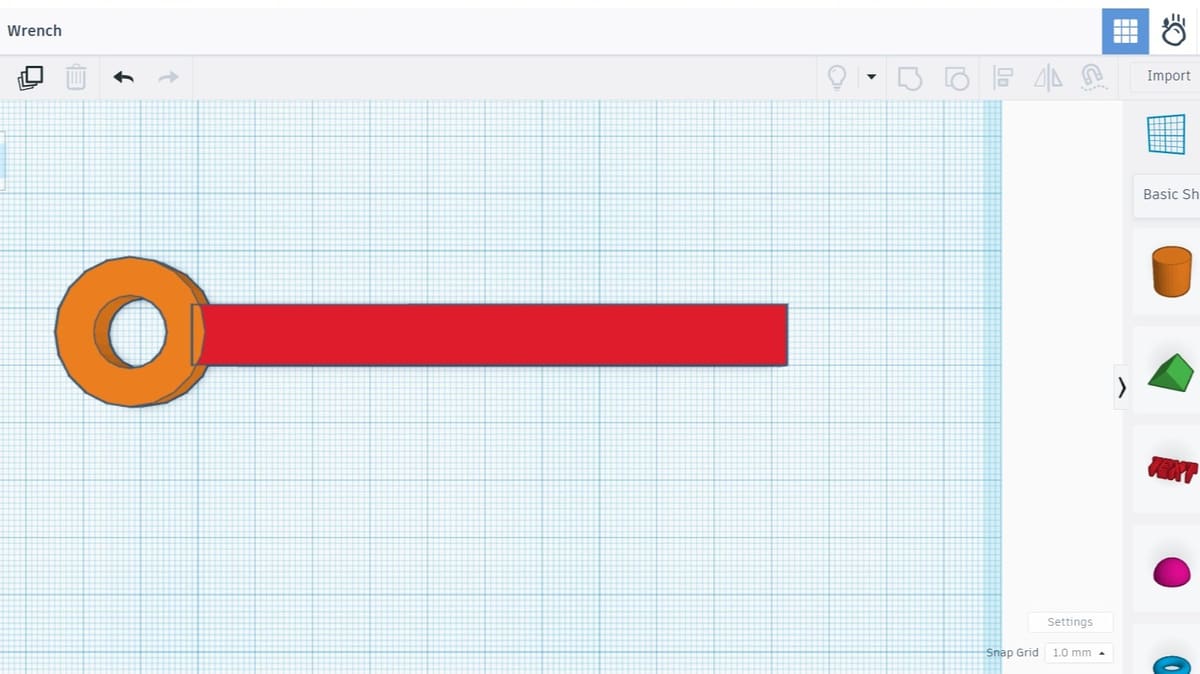
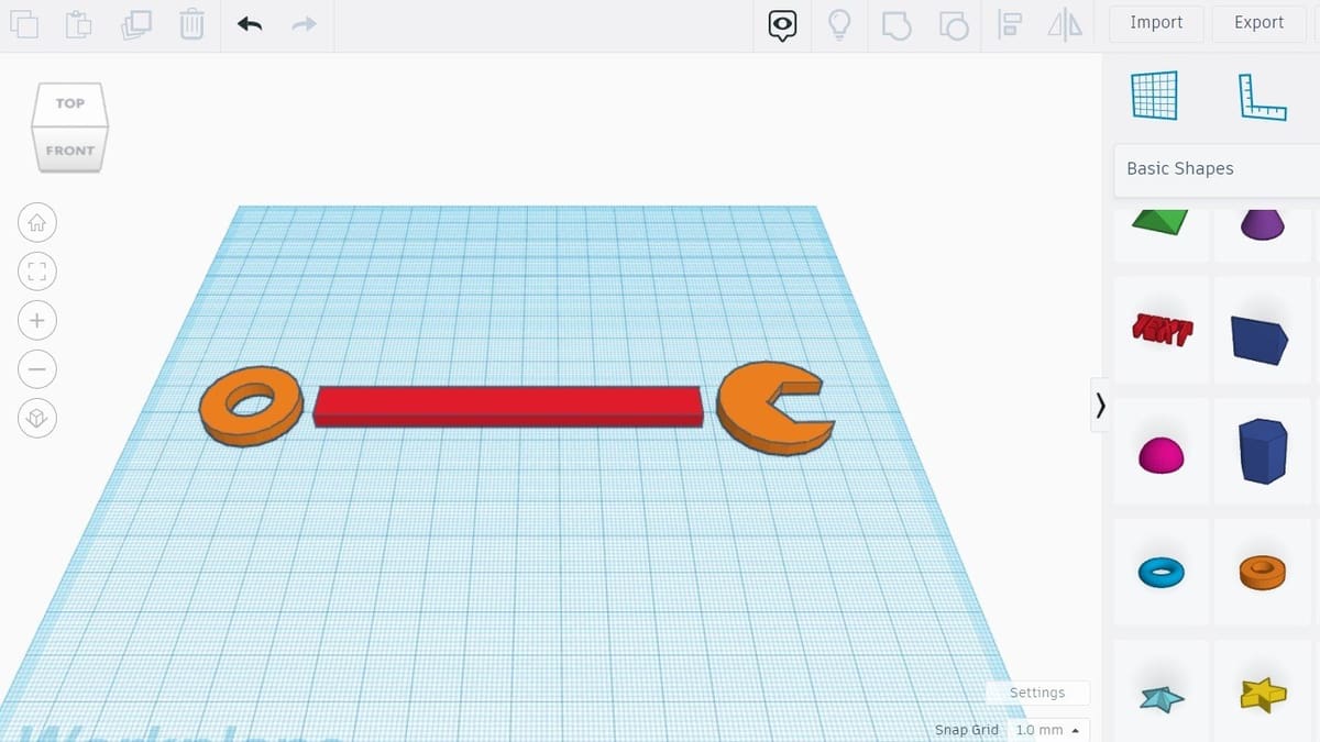
To put everything together, let’s start with the handle and the ring. Align both shapes just like we did in the last step – that is, just in the “long” direction. Then, hold Shift and move the ring in a straight line toward the end of the handle. Make sure to overlap the two shapes just a little bit (using the image above as a reference), and when that’s done, go ahead and group them.
This should merge the handle and the ring into one continuous unit. Notice that it now has a single color instead of two.
Now, let’s attach the jaw to our not-quite-finished wrench. In our case, the jaw is facing the wrong direction. We need to fix that by rotating it.
Rotating
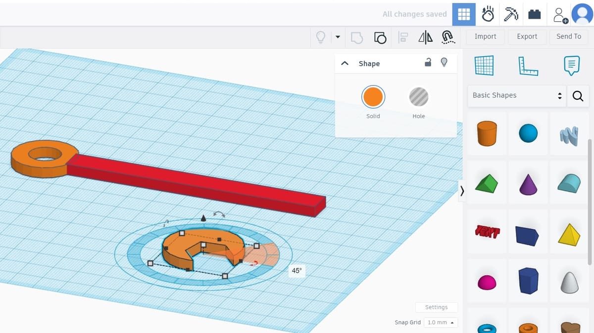
First, select the jaw by left-clicking on it. In addition to the white handles, note the three curved handles with double arrows. Hovering your mouse over the one on the bottom (XY) plane will cause an angle value to pop up.
To rotate the jaw, either click and drag the handle around the shape or enter a value manually. Here, we need a 45-degree rotation counter-clockwise. (Tip: Holding Shift will limit the rotations you can snap to.)
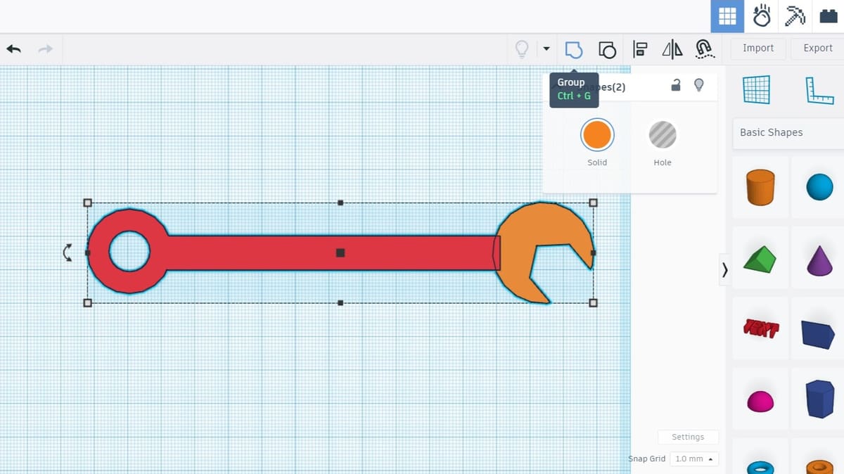
All that’s left to do in this step is to align and merge the jaw. The procedure is more or less the same as what we did to join the ring and the handle.
Align both shapes first and then drag the jaw while holding Shift towards the wrench. Once more, position them so that they overlap a bit. Finally, group them!
Changing Colors

You should have a complete wrench on your workplane. How cool is that? Although, an orange wrench is kinda weird. Let’s change its color before moving forward.
To do this, select the finalized wrench and click on the “Solid” button on the Shape window. A broad selection of colors will be displayed. Let’s go with a dark gray.
Looks better, right? In reality, this will have little effect on your final model, but color-coding multi-part designs can make designing more organized and therefore easier.
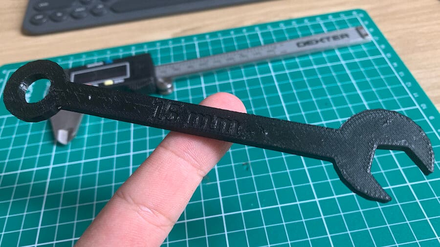
And there you have it! A perfect wrench on your workplane.
Step 5: Adding Text
So, now that our wrench looks like a wrench, you might consider 3D printing it. Indeed, with the skills you’ve acquired so far, you’ll be able to design and print an entire wrench set!
But would you be able to differentiate each size just by looking? Probably not. So, in this final step, we’re going to add the size information directly onto the handle.
To do this, look for “Text” in the Basic Shapes panel and drag it to the workplane. Text works like any other shape, but we can change its content. Since we want to “carve” the text out of the handle, make it a hole.
Adjusting & Positioning
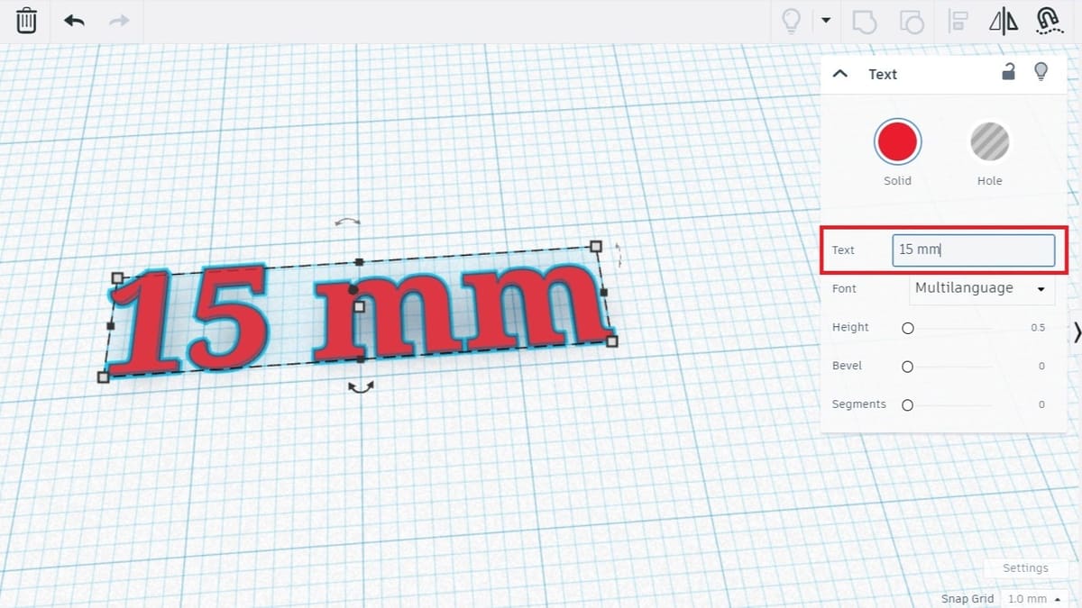
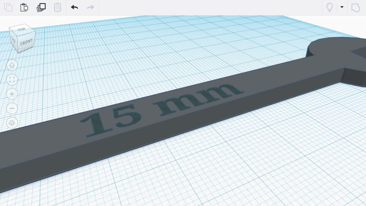
Let’s change the text content. In the Text window, click on the “Text” field and replace it with “15 mm”, which is the size of our wrench. The shape will automatically change.
Now, it’s just a matter of sizing the text and merging it with the wrench. Adjust its length and width to be 32 and 7 mm, respectively. Depending on how deep you would like the letters to be, you can adjust the height. We used 0.5 mm.
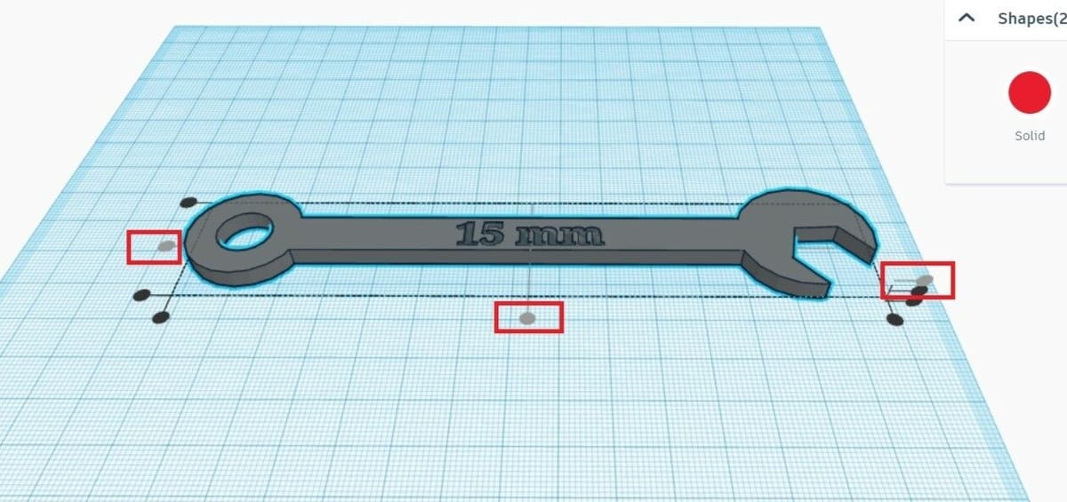
To position the text over the handle, let’s once more use the alignment tool. Select both shapes and hit “Align”. Since we want the text to “dig” into the top of the wrench, we’ll select the top round handle along the vertical dimension, as shown below.
This will make both shapes’ top surfaces flush. Finish placing the text by clicking on the middle round handles in the XY-plane. All that’s left now is to carve the text by merging the shapes, and everything should be set!
Stacking Objects
If you want to emboss the text so that it sticks out of the handle, you’ll need the bottom of the text to be flush with the top of the handle. Here’s a handy trick for lining objects up in this fashion:
- Temporarily move the workplane by pressing the “Workplane” button found above the Basic Shapes panel (or ‘W’ on your keyboard) and clicking on the appropriate surface. In this case, that would be the top of the wrench.
- Select the other object – the text for us – and press ‘D’. This will rest it on the temporary Workplane.
- Cancel the temporary workplane by pressing the “Workplane” button and clicking away from any objects. All objects will retain their positions.
Cruising with Objects
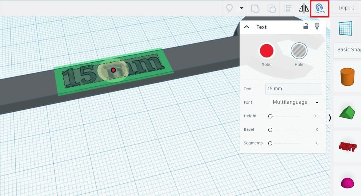
In the spring of 2023, Tinkercad introduced a new feature to make positioning objects together even easier called “Cruise“. This tool can be found in the top toolbar and looks like a magnet. Cruise can be enabled when an object is selected and allows for the snapping of shapes to surfaces of other shapes without having to establish an alternative workplane.
In our case, instead of the procedure described above to align the embossed text to the outer surface of our wrench, all we would have to do is select the text and enable “Cruise”. From there, click and drag the circle that appears on the text to position it on the wrench handle. You’ll notice the text automatically moves to the outer surface of the wrench when it makes contact. It’s as simple as that!
With Cruise enabled, the shape can also be rotated and scaled while staying in alignment with the surface it sits on.
Optional Step: 3D Printing Your Model
Now, you should be ready to 3D print your first Tinkercad part. After all, who doesn’t want to see their creations come to life? If you have a 3D printer, you can print the wrench, use it in your daily life, and show off your maker skills to all your friends.
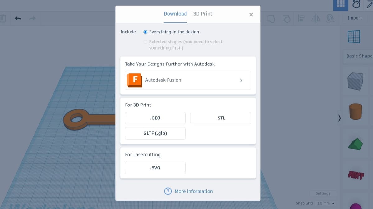
To get there, first click on “Export” and choose either the STL or OBJ file format. This should promptly open a download window. And off you go! Make sure to choose a durable material and set a high infill percentage if you’re planning on using the wrench to tighten anything.
If you want to continue working on your model and you feel comfortable in a more advanced program like Fusion, you can click on the button that connects you with the option to send it to the program. From the page, you’ll be able to decide what type of task you want to carry out and you’ll then need to confirm some information to send it to the software.
Last but definitely not least, if you’re working on more than one model or object, you can choose to export either everything that’s in the workplane or a specific model. The former will be the option by default, unless you select a specific part before exporting.
Using a Service
If you don’t have a 3D printer, you can submit your design to a 3D printing service that will print and ship the model to you.
To get the best price, you can use Craftcloud. With plenty of partners around the world and a wide variety of materials and 3D printing technologies, you can decide how you want your Tinkercad designs to be. The best part? They’ll be delivered right to your doorstep!
Optional Step: Simulation
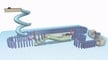
If you’re working on a design that includes various models or parts that are meant to interact with each other, you can simulate what the interaction will look like at the Sim Lab.
Once your parts are set, instead of exporting, click on the falling apple (hi, Newton!), which will read “Sim Lab” if you hover over the symbol. From there, you’ll be led to a slightly different workspace.
In the Sim Lab, you can see what gravity will do to your setup, add materials and colors to the different objects, and build machines to see how they would work. You can add throwable objects so that, when you’re playing the simulation, by clicking at different parts of the screen the selected objects will – you guessed it – be thrown and affect the setup.
So, with Tinkercad you can learn about basic modeling and interconnecting of parts, design things to be 3D printed, and simulate how they’d behave in reality. As you can see, there are plenty of reasons to use Tinkercad!
That's It!
We hope you’ve enjoyed this Tinkercad tutorial. If you face any difficulty or confusion when following the instructions, let us know in the comments, and we’ll try to help you out.
A few common questions that come up about Tinkercad are whether it works offline, what other cool design projects you can work on or get inspiration from, and, if you’re really into upping your game, how you can combine Arduino and Tinkercad for incredible projects.
Let your imagination take flight with Tinkercad!
License: The text of "Tinkercad Tutorial: 5 Simple Steps to Success" by All3DP is licensed under a Creative Commons Attribution 4.0 International License.