Tinkercad & Arduino: How to Design and Simulate Circuits

Tinkercad Circuits combines Tinkercad with Arduino circuitry. Learn about the capabilities of this new partnership and see what it can do.
Tinkering With Arduino
In the world of 3D modeling, Tinkercad has established itself as a worthy introduction to computer-aided design (CAD). It’s a free and intuitive web-based CAD program that anyone can use. In fact, if you want to get started with Tinkercad, we even have a beginner’s tutorial to get you going.
Recently, Tinkercad has introduced something new: An expansion to include circuits in its design capability called Tinkercad Circuits. This brings a whole new side to Tinkercad, revolving around simulating circuits with Arduino.
Arduino is an open-source electronic prototyping platform that also sells microcontrollers. Tinkercad Circuits allows anyone to virtually create and program Arduino projects without the need for physical hardware.
In this article, we’ll be showing you how to program a basic Arduino in Tinkercad, but first, let’s take a closer look at the new capabilities Tinkercad Circuits offers.
What Do Circuits Add to Tinkercad?
As we mentioned before, Tinkercad Circuits opens up the possibility of electrical functionality in your 3D printing projects. To that end, in the user’s dashboard, you can find a whole section devoted to circuit projects. It’s organized similarly to the CAD project gallery, making it easy to navigate. You can also find circuits in the “Gallery” and “Learn” pages of Tinkercad.
Tinkercad has also introduced something extra to combine these two worlds: Its CAD environment now comes with circuit component models. This means you can design a model with circuits and hardware, and once 3D printed, the circuit can be easily placed within the creation.
Of course, we can’t overlook the new circuit simulator. Let’s dive in!
The Design Suite

Once you decide to create a circuit, you’ll be using the new Tinkercad Circuits environment. It may seem like a lot at first, but don’t be intimidated – we’ve got all the information you need to succeed. You’ll quickly see that this creative platform is an excellent prototyping tool.
Building Area
On the right side of your screen, you’ll see a group of drag-and-drop electronic components. On top, you can search and filter through an impressive number of available components: There’s everything from LEDs to integrated circuits (ICs), and even a few instrument tools.
The open building area is where you design your creation. The top toolbar starting on the left gives you the general operations to rotate, delete, and even make notes on your different components. A cool feature is that, in addition to exporting and sharing your work, you can download the component list. This makes it easier to bring your creations into the real world.
Programming Area
Once you have a programmable component in your design, you can open the “Code” viewer by clicking on the button at the top right of the toolbar. Currently, the only two devices available are the Arduino Uno R3 and the ATTiny. (The ATTiny is a more limited and miniaturized Arduino.)
The programming area is a simplified integrated development environment (IDE) that makes programming the Arduino very straightforward. The default method is via code blocks, which we’ll look at later, and there’s also a dual view for learning how the code blocks translate to actual code. For those who are already acquainted with the Arduino library, there’s even a text view.
Mini Project
Now that you know the basics of Tinkercad Circuits, let’s get our hands dirty making a simple circuit. In the following, we’ll insert an output (an LED) and an input (an ultrasonic sensor), controlling everything with a programmed Arduino. Together, it’ll work like a simulated rangefinder.
Select “Create new Circuit” to get started!
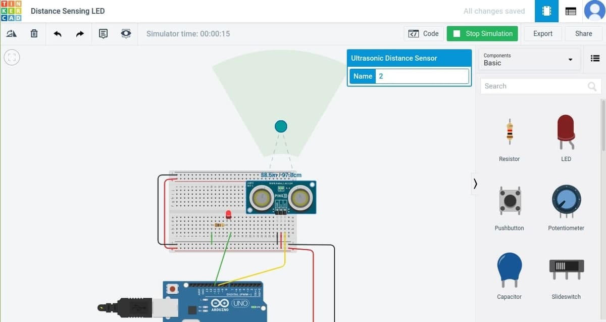
Step 1: Making the Circuit
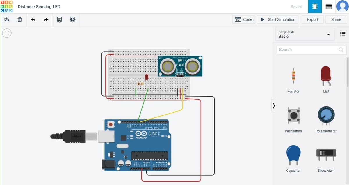
To start, we must build our circuit. You’ll need a breadboard, an LED, an ultrasonic sensor, and the Arduino Uno.
- Drag and drop these components into their respective places. To rotate them, you can use the hotkey “r”.
- Follow the image and place each part as shown. Notice that the breadboard is used to connect the components together. It contains a series of columns and two rails on each side.
- As you click from pin to pin, you’ll create wires, each of which can be color-coded for easy identification. When a wire is selected, you’ll see the item options pop up with a dropdown menu to change its color and other characteristics, like resistor value. Set the resistor value to 100 Ω.
- Ensure that the LED is connected to pin 11 and that the ultrasonic’s signal is connected to pin 10.
Once everything is in place, we can begin programming.
Step 2: Programming the Arduino
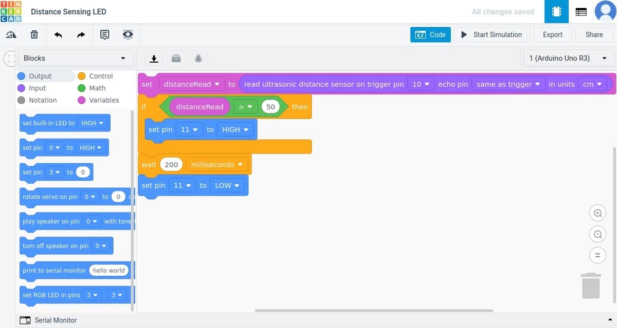
As you can see in the above image, we’ll be making a simple four-block program. To begin, select “Code” from the top right toolbar, which will open the code block editor. The list of blocks is color-coded by type.
- Create the first block, which is a variable block. This creates a placeholder for a value (input), which in this case is the reading we get from the ultrasonic sensor. To accomplish this, the block should read “set distanceRead to read ultrasonic distance sensor on trigger pin 10 echo pin same as trigger in units cm“.
- Create the next block, an “if” statement, which is a type of control block that makes a decision. In our case, the decision is based on our distance reading. Our placeholder checks if the value is greater than 50 cm: “if distanceRead > 50 then“. If it is, what’s inside the block is executed: “set pin 11 to HIGH“. This basically turns on the LED.
- The last two blocks may seem strange, but they make sense when you understand how an Arduino works. When it turns on, its program runs continuously in a loop, meaning you need to reset the LED for the next time it goes around. That’s why the last output block turns our LED back off. And in order to see our LED blink, we have to place a small delay between loops. Implement this functionality with the first block set to “wait 200 milliseconds” and the second to “set pin 11 to LOW“.
Once you’re done, select “Start Simulation” on the toolbar to turn on your Arduino Uno. To simulate an object in front of the ultrasonic sensor, select it and drag the dot that appears. Watch how the LED responds to our predetermined limit.
Troubleshooting: If your program doesn’t behave as expected, check your wiring and programming. Ensure that all pins are properly connected and that each block is written correctly.
If everything seems to work, congratulations! You can always continue to play around with the code and different components to learn more about how everything works.
Explore the Possibilities
There’s no doubt that Tinkercad has expanded its horizons. With the addition of Circuits and its many features, the possibilities are endless. From the plethora of components to the comprehensive code blocks, there’s a lot to explore.
As any good maker knows, the best way to learn is by doing. If you’re not sure where to start, we have a list of the coolest Arduino projects currently out there.
There are plenty of learning resources, as well. Here are a few that you might want to check out:
Enjoy and happy tinkering!
(Lead image source: circuits via Instructables)
License: The text of "Tinkercad & Arduino: How to Design and Simulate Circuits" by All3DP is licensed under a Creative Commons Attribution 4.0 International License.