SolidWorks Tutorial for Beginners: How to Get Started

SolidWorks is a popular program for mechanical modeling, and it's very useful to know. Follow this SolidWorks tutorial to get started!
SolidWorks is a technical modeling software developed by Dassault Systèmes. Its main applications are modeling and drafting for mechanical and electrical engineering, as well as for manufacturing applications.
SolidWorks is often used in academic and industry settings because of its complete and complex range of tools, allowing you to model just about anything. However, it’s important to note that SolidWorks isn’t the recommended tool for artistic modeling.
This means that if you want to model characters or carry out organic modeling, you’d be better off using other modeling software like Blender. In contrast, if you want to do highly technical models, like combustion engines, gearboxes, and even your own 3D printer, SolidWorks is a tool ideally designed for such applications.
Needless to say, SolidWorks is a great tool to have in your arsenal, and learning it could give you the advantage you need. In this tutorial, we’ll teach you about creating parts and assembling them. We’ll also go over the drawing environment. Because they’re more advanced features, we won’t be covering CAM and simulation in this beginner tutorial – which isn’t too much of a loss because many professionals use other, more complete platforms for CAM and simulation anyways.
But before we jump into the tutorial, let’s cover some basics.

Getting Started
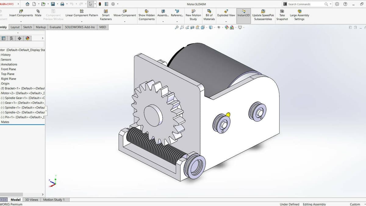
When working in SolidWorks, there are three main work modes you can choose: Part, Assembly, and Drawing. These also correspond to file types. Part is used, as the name indicates, to create parts of a bigger element, draw their sketches, and extrude volumes. Assembly is used to unite different parts in the same environment via mates. Drawing is used to make a blueprint of your model. It can be used for both parts or assemblies.
In this tutorial, we’ll model two parts: a vase and a lid for it. We’ll then assemble them and create a blueprint of the assembly.
Some recommendations before getting started:
- SolidWorks parts, as default, are saved as .sldprt file, meaning “SolidWorks Part”. This file contains information about operations made to create the volumes and also considers the model as an assembly of surfaces, edges, and vertices, not a mesh. This is the best file format to work with if you’re going to be modifying your model or if you want to work on blueprints or assemblies.
- If you want to ensure compatibility between versions of SolidWorks, the recommended file IGES. It won’t save operations, but it will keep the face as surfaces, edges, and vertices, instead of a mesh, so you can still use those parts for assembly and drafting.
- If you intend to 3D print your model after you’re done modeling, you can save it as an STL file, which is perfect for slicing.
Modeling
UI Overview
Before getting started on each stage of the pipeline, we’ll go over the most important parts of each environment.
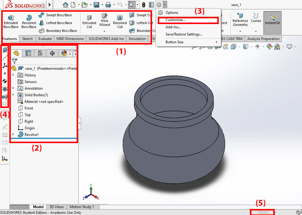
In SolidWorks, the area where you see your drawing is called the “Viewport”. On top of the Viewport is the Command Manager (1), a menu divided into tabs. The main tabs you’ll use, as a beginner, are Features and Sketch.
In Sketch, you can find tools to draw two-dimensional shapes, which can then be converted into three-dimensional objects using the tools on the Features tab. On the Evaluate tab, you can find useful tools like Measure, which gives you dimensions between selected surfaces, edges, circles’ center points, and so on. Other tabs like Simulation, Motion Studio, MBD, and CAM have more advanced features that won’t be covered in this tutorial.
To the left of the Viewport, you can find the FeatureManager Design tree (2). Hidden in tabs are other menus, including PropertyManager under the second tab. The FeatureManager Design tree lists all of the objects and operations present in your Viewport. This includes planes, the origin point, sketches, volumes, cuts, and even the material of your part.
On top of the Command Manager, you can find a quick menu with buttons such as New, Save, Open, and Settings. To display more option menus, hover over the SolidWorks icon on the top left, and the full menu will unfold. If you want to add additional feature menus, you can do so by clicking on the arrow to the right of the Settings icon and selecting “Customize” (3). For example, we’ve pulled the “Reference Geometry” (4) tools to the left of the FeatureManager Design tree.
Finally, our model is going to be in millimeters, so make sure you have the right unit system (5) on the lower right of the viewport.
And with that, let’s get into our tutorial.
Creating a Sketch & Lines
When you want to create a part, you’ll always start by doing a 2D drawing of it, transforming it into a 3D volume, and repeating that same process until the part has all the details you want.
Select a plane to work with, available in the FeatureManager Design tree. In our case, we’ll start with the right side plane. In the Sketch tab, select the “Sketch” button (1), which will start a new sketch. Once you’re done, click on it again to exit Sketch mode.
Step 1
The first step inside the sketch will be to create a line (2). There are three tools you can use to create lines:
- Line: This is a normal line whose starting point will be one of the endpoints of the line.
- Centerline: This type of line helps you to draw the sketch but doesn’t count as a solid line or an edge of the sketch, meaning it has no influence when extruding unless you use it specifically as a center line for a revolution. This tool is a bit of an inconsistency on SolidWorks’ part because it’s present in both the line and the reference geometry menus. Even though they behave the same way, it’s called a “Construction Line” in the former and a “Centerline” in the latter. With the name Centerline, SolidWorks assumes it will be used as a center axis for a revolution, but in fact, it can be used for anything.
- Midpoint Line: The starting point for this type of line is its center.
For our purposes, we’ll use Midpoint Line to create a line starting from the origin. To do this, start by clicking on the origin, which will automatically create the midpoint relation between it and the line. Then, drag the mouse outwards vertically, and the line will have equal dimensions in both directions.
Pro Tip
There’s a difference between starting our vase with the Midpoint Line and normal Line tools. With the way we did it, the center of gravity is now located in the origin. In contrast, if we had used the normal Line tool, the center of gravity would be above the origin. You can access this measurement on the Evaluate tab.
At this stage, it doesn’t matter whether we used Midpoint Line or normal Line, but it’s good to know the difference between them. For example, in SolidWorks certification exams, questions will ask you to model a part and provide its center of gravity. The answer will depend on how you modeled it.
Step 2
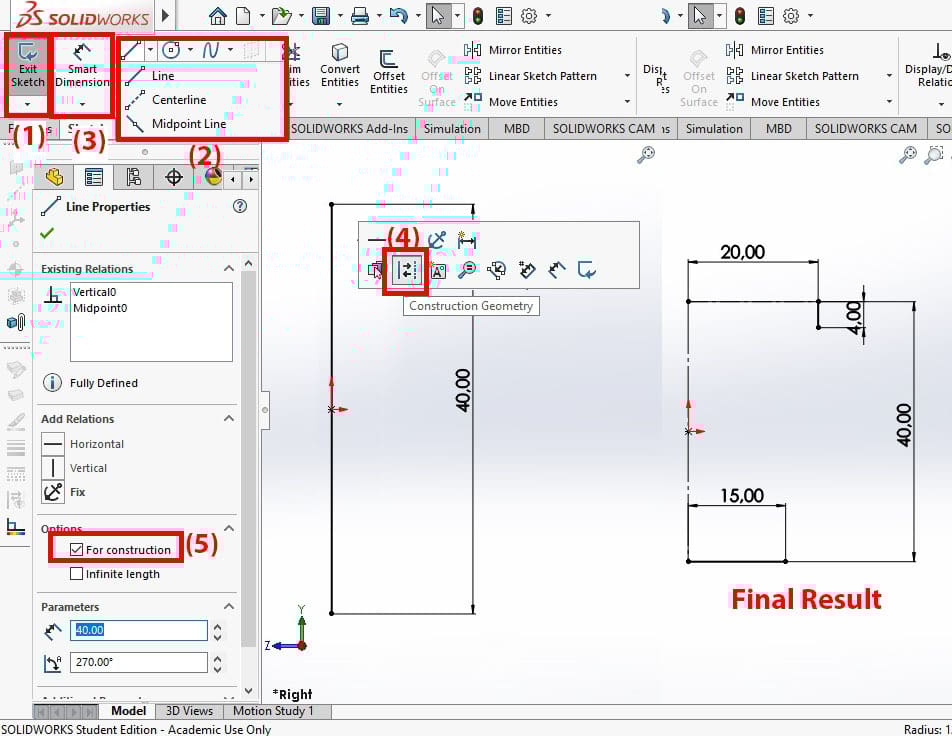
The next step is to add a dimension. For this, we go to the “Smart Dimension” button (3) and click on the line. This will create a dimension Line – in this case, for the length of the line. Set this value to 40 mm. This will be the total height of our vase.
Step 3
Now, we want to convert this line to a construction line. There are two ways to do this:
- Select the line and leave the mouse hovering over it. You’ll see a symbol (4) there representing line-to-construction-line, and you can select it.
- You can also select the line, and the Line Properties menu in the PropertyManager will show a checkbox that says “For construction” (5). Check it, and the line will become a construction line.
Step 4
We’ll create two horizontal construction lines, or “Centerlines”, to signify the top and bottom boundaries of the vase. We’ll dimension the top one 20 mm and the bottom one 15 mm. Convert the bottom line so it’s not a construction line. Then, create a short vertical line at the edge of the top line, and make it measure 4 mm.
3-Point Arcs
In SolidWorks, you have the option to create complete circles or arcs, which are a section of a circle. There are three ways to create an arc: from a center point, from a tangent point, or the most common one, a 3-point arc.
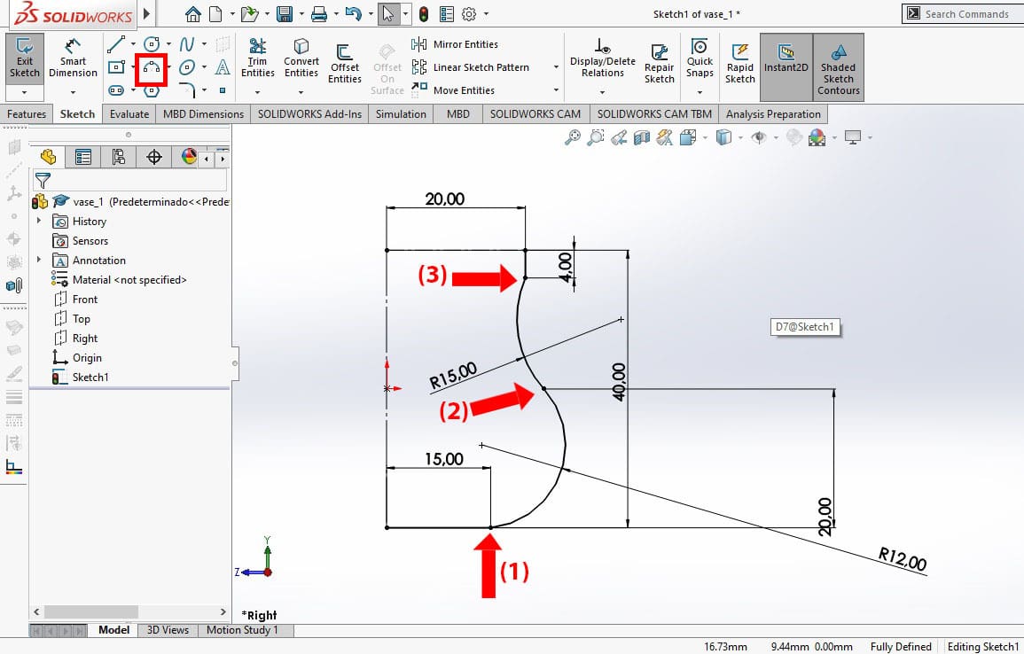
In this case, we’ll create two 3-point arcs to make the curves on the vase. One will be facing outwards and the other one inwards as shown in the image.
Step 1
To create a 3-point arc, you have to click where you want your starting point to be. This will automatically create a Coincident relation. A Coincident relation means both points are coincident in position, or in simpler words, they’re now attached (more on this later).
Then, select the finish point or the arc, and finally, drag the mouse around to change the radius of the arc. You can change these characteristics later by using dimensions. Repeat these actions to create the second arc.
When creating the two arcs, the bottom one should have a starting point coincident with the bottom line (1), the finish point should be the same as the start point of the second arc (2), and the finish point of the second arc should be coincident with the 4-mm vertical line (3), as can be seen in the image above.
Pro Tip
In SolidWorks, you can make any elements in a sketch have relations to other elements. Relations include Parallel, Coincident, Perpendicular, and more. The selected relation will snap the sketch’s elements into the position you indicated, as long as it doesn’t interfere with previously set relations.
Step 2
We need to make sure the two arcs are tangent to one another to have a smooth surface without edges. For this, select both curves while holding the Shift key, and a hover menu will appear with the Tangent icon.
You can also select this option from the PropertyManager on the left side.
Step 3
Next, we’ll add the following dimensions: for the bottom arc, a radius of 12 mm, and for the top one, a radius of 15 mm. For the connection point of the two arcs, we’ll assign a height of 20 mm.
These dimensions can be modified up to your taste, as this model is a vase. For more technical models, however, it’s important to be exact and adhere to norms when necessary.
Finishing Up the Sketch
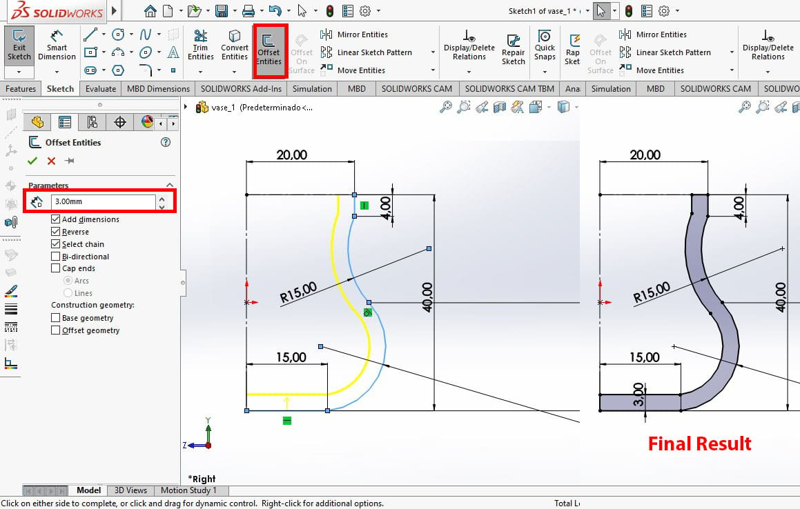
Now, it’s time to give the vase a thickness. Otherwise, it would be solid, but we want to it be hollow. We could draw new lines from scratch and add dimensions. However, there’s a more exact and time-efficient way to do this: a tool called “Offset Entities”.
- To use Offset Entities, select all lines that aren’t for construction by holding the Shift key, then select the Offset Entities button.
- The PropertyManager will show you a set of options to toggle with. The main one is the thickness, which we’ll set to 3 mm.
- Make sure that the yellow preview line is pointing inwards, if not, you can check the box that says “Reverse” to invert it.
After adding the offset, close the shape with two lines at the open ends. You should know if your sketch is correctly closed now because it’ll have a blue shadow filling.
Pro Tip
You can only do 3D operations to a closed sketch, whereas surface operations can be done to sketch lines whether they’re open or closed. For example, if you try to extrude a base with an open sketch, SolidWorks won’t be able to solve the asked operation, and it’ll ask you to check your sketch for open lines.
Creating a Volume
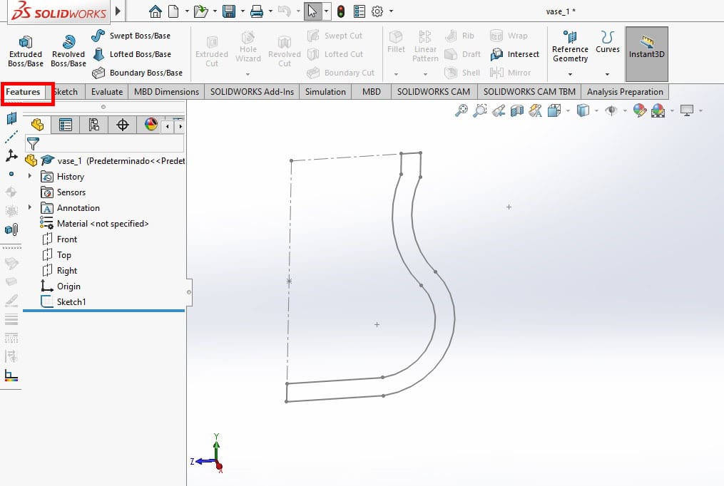
Once a sketch is done, it’s still a 2D figure instead of a 3D one. There are several ways to change this, as you can see in the Features tab. This tab is divided into sections to create a base/boss, to make cuts, and various other features like patterns, fillets, or shells. Additional features can also be found in the menu under “Insert > Features”. To make this menu appear simply hover over the SolidWorks logo on the top right.
In our case, we’ll be using the Revolved Boss/Base feature, which revolves a sketch around an axis to create a volumetric shape. The first construction line we created in the sketch represents the axis.
- To create a revolved base, select the sketch in the FeatureManager Design tree.
- Then, simply click on the Revolved Boss/Base button and the PropertyManager will open the Revolve menu. Here, you first have to choose the Axis of Revolution.
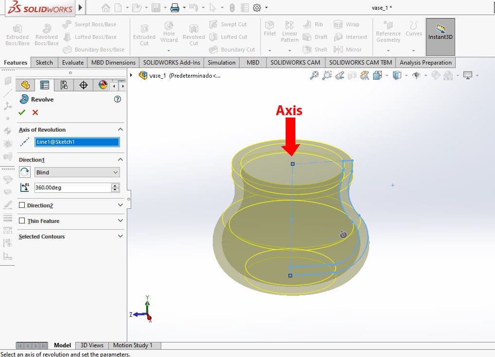
- Click on the axis line in the sketch, and you’ll automatically get a preview of how your object will look.
- Additionally, you can change the angle of the revolution. In our case, we’ll leave it a 360° to have the whole revolution.
- Finally, click the okay button, and your revolved base will be done.
Pro Tip
You’ll notice that we only sketched half the vase prior to using the Revolved Boss/Base tool. When creating irregular cylindrical objects like vases, bottles, funnels, and similar shapes, revolving the sketch around an axis is the most efficient method for modeling them in SolidWorks.
When selecting the sketch to revolve, the best practice is to select the sketch directly in the FeatureManager Design tree. The lines of the sketch can also be selected directly in the Viewport, but this can sometimes lead to mistakes. The program can wrongly interpret your selection, leaving some lines out.
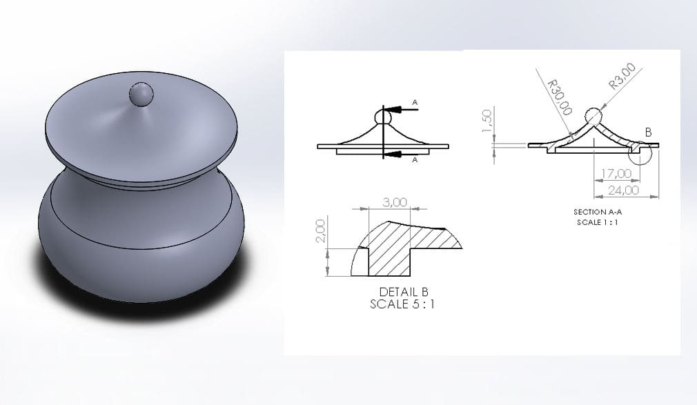
Sketching the Vase Lid
Creating the lid is very similar to the process we used to create the vase. We’ll model half of it, then do a revolved cut. In this first part, we’ll go over the main shape of the lid, and in the next, we’ll add additional details.
- Create a new part.
- Start a new sketch on the right side plane, shown in the FeatureManager Design tree.
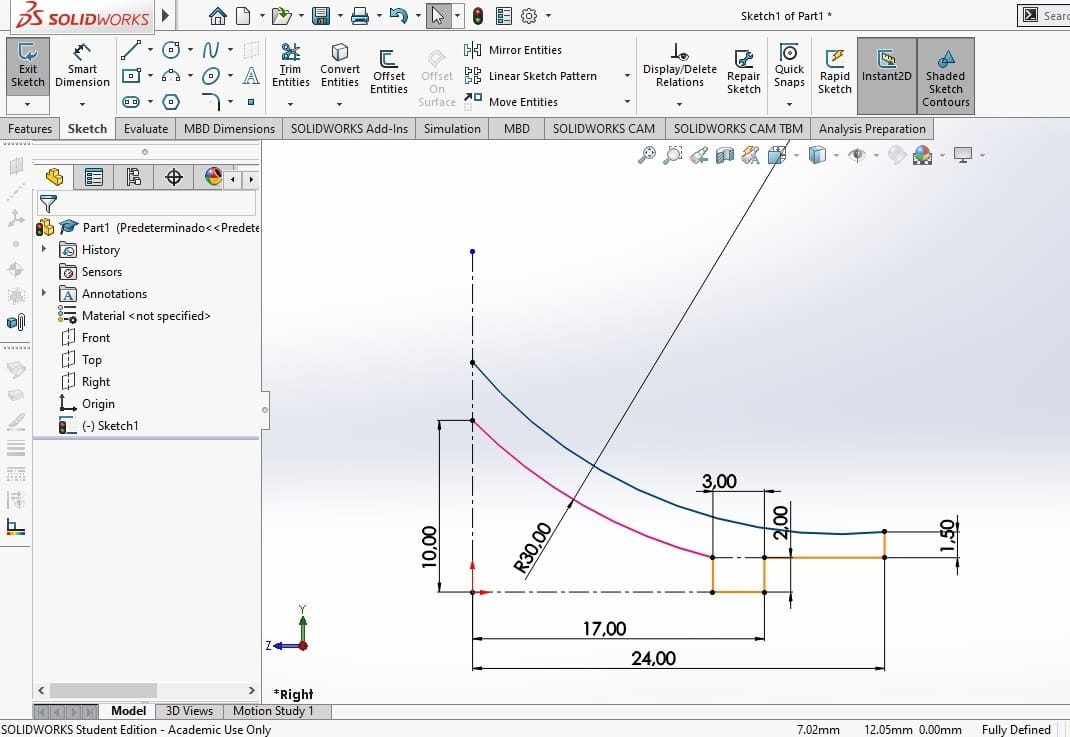
- To create most shapes shown in the image, you’ll only need the Line, Construction Line, 3-Point Arc, and Smart Dimension tools. Create the shapes signaled in orange, then we’ll go through the more complicated ones after.
- To create the curves, start with the one signaled in pink. Select the points to cross the orange line and the construction line.
- Set the dimensions as shown in the image above.
- Create the blue curve in a similar way.
- While holding the Shift key, select both arcs and add a Concentric relation, which will ensure that the center point of both curves is located on the same coordinate.
Now, both curves have the same center, and the radius of the blue one is defined by the coordinates of previous lines.
Circles & Trimming
At the top of the lid, we’ll have a spherical handle. Whenever you want to make a sphere in SolidWorks, the function Trim Entities is the way to do it. This tool allows you to trim lines in a smart way, keeping or deleting relations as the program sees fit and saving you work.
The following steps will show you how to use Trim Entities, as well as other tools, to create the spherical handle.
Step 1
First, we’ll need to add a circle. To make circles, you need to select a center point as well as an external point that defines the radius. This second point doesn’t matter as much, as the radius’ dimensions can be easily changed. Changing the center point, however, is more troublesome, so make sure you get it right from the start.
So, let’s start by creating a circle with the top of the blue curve as the center point. Give it a diameter of 6 mm.
Step 2
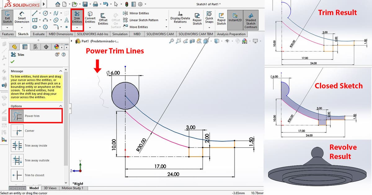
Since we’re going to revolve this sketch as well, we only need half the circle. While we could do this with a 3-point arc, it would be more work. So, click the Trim Entities button as shown in the image above.
There are several ways to use the trimming tool, but by default, it should be set to “Power Trim”. Simply drag the mouse while left-clicking over the line you want to cut. If you’re doing this correctly, you’ll see a thin gray line indicating where your scissors will trim.
For our tutorial, we want to trim the left side of the circle, so drag your mouse over it. SolidWorks will detect the limits of the intersection with the construction line and delete anything before it, leaving only the right side of the circle.
Do the same to the other lines intersecting the circle and blue line so that it matches the trim result shown in the image above.
Step 3
Finally, close the sketch with a line on the left side and do a revolved base.
Pro Tip
If you don’t trim the circle, SolidWorks will find conflict in the revolution because it would essentially try to revolve over itself at one point. Similarly, if you don’t trim the overlapping solid lines, the revolution will also fail.
Assembly
Overview

To create an assembly, we need to create a new file by clicking on the New icon, then selecting “Assembly” on the New Document screen.
From the start, you’ll be asked to select components to have in the assembly. So, you can go ahead and select the vase and lid, or you can press “Cancel” and do it later. To add them to your Viewport, just click anywhere in it and they’ll appear. Make sure the different elements aren’t touching when you add them, or you could add accidental mates.
On top, we still have the Command Manager, but it now shows assembly tools. The two most important are Insert Components (1), which is where we go back and add more components, and Mate (2), which is where we add relations – called “mates” – between objects to make them have contact in a certain way.
There are also sketch tools in the Sketch tab (3), which can be useful when you’re figuring out a design. Finally, we also have the Evaluate tab (4) with features like Hole Alignment and Measure, which can be useful if you’re going to add a distance mate but need to verify distances first.
Mates

As the mates are the main point of discussion when assembling, we’ll go over what each of them does. Please note that when we mention “edges” below, we’re referring to the lines of the part.
- Coincident makes two surfaces or edges be in contact. It works for planar parallel surfaces, meaning it’s not compatible with curves. This mate works as long as the two surfaces or edges exist on the same plane: For example, they’re both horizontal. It can also be done between an edge and a surface.
- Parallel makes two surfaces parallel to one another, although not in contact with each other. It can work with curves of constant radius or planar surfaces.
- Perpendicular makes two surfaces perpendicular to one another, although not in contact. It only works with planar surfaces.
- Tangent works between either two curves or a curve and a plane. It makes the two surfaces tangent to one another – meaning there’s only contact at one point.
- Concentric positions the center points of two circular surfaces of constant radius at the same coordinates.
- Distance separates two planar surfaces by a specified distance.
Additionally, you can only add a mate as long as it doesn’t interfere with previously added ones. For example, if you make two planes Perpendicular, then try to make them Coincident, SolidWorks won’t let you.
Aside from standard mates, you can also find advanced and mechanical mates in the expanding menus below the standard options. Of these, mechanical mates are the second most used after the standard ones, as they contain mates for gear ratio, screws, and rack-pinion.
Pro Tip
Edges don’t have to be straight as long as the parts to be “mated” have the same radius. However, edges do have to be on the same plane. For example, one can’t be a vertical circle and the other one, a horizontal circle. If you have two horizontal planes or edges and you make them Coincident, you’re essentially telling them to be at the same height.
Adding Mates to Our Assembly
The first thing to note is that the first object added to an assembly becomes automatically fixed, and all other elements float. This means that the fixed element remains static, and when you add mates, they will move towards the fixed element.
Depending on what you’re doing, you should make sure that the correct object is fixed and that all others are floating. To switch from fixed to floating, right-click the element on the FeatureManager Design tree. If the object is fixed, the option will read “Float”, and if it’s floating, it will read “Fix”.
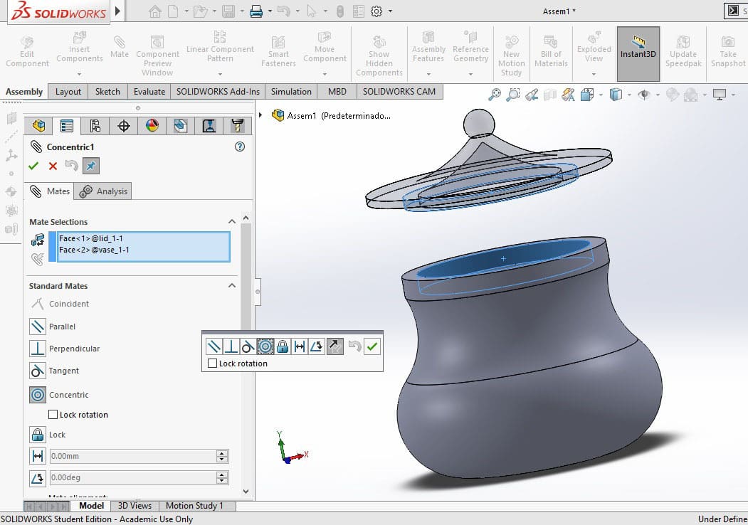
- In our case, we’ll leave the vase fixed and the lid floating. This means that, when we add mates, the lid will move towards the vase.
- We’ll add a Concentric relation between the lid’s outer circumference at the vase’s inner circumference, as indicated in the image. For this, simply click on “Mate > Concentric”, and select both surfaces. Alternatively, if you select both surfaces without selecting the kind of mate, the program will select the mate that makes the most sense with the surfaces given – in this case, Concentric.
- Add a Coincident mate between the bottom of the lid and the top of the vase.
Drawing
UI Overview
As soon as you go into the Drawing environment, SolidWorks will ask for some information. In the next section, we’ll walk you through what to do, but let’s first get acquainted with the Drawing environment’s UI.
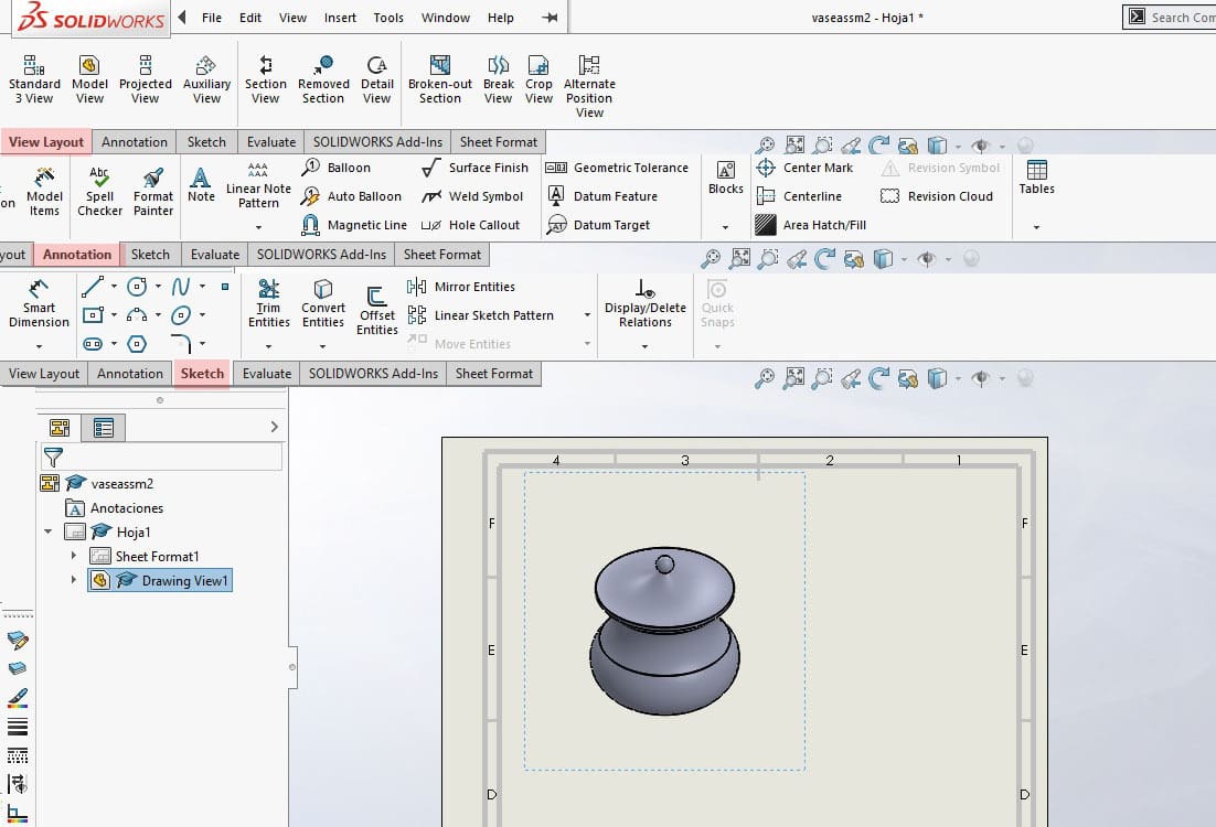
On the command manager on top, the first tab is View Layout, which has tools to project views from the model, do cut sections, or show details when they’re too small.
The following tab is Annotation. It has all the symbols for technical blueprints, such as balloons (which are used to number parts), weld symbols, center marks, centerlines, and tables (which are used to automatically create a bill of materials of all present elements in the drawing). It also has smart dimensions, which is the most important part of a blueprint.
In the Sketch tab, you’ll find the traditional sketch tools in case you need to further explain something in your drawing. These are the three most important tabs to know when working on a drawing.
Pro Tip
How you use the Drawing environment’s tools will depend greatly on your country’s and company’s regulations for technical drafting.
Setting Up Your Drawings
When you first open a drawing, it will ask you to select a format. What format you select depends on the ones you have available or the regulations in your country and company. If you have a personalized one, you can use that too.
SolidWorks has a lot of formats available by default, and for this project, we’ll use A4. Once the format is selected, it automatically opens the option to browse for a part or assembly to put on the blueprint, but you can also choose to add objects later.
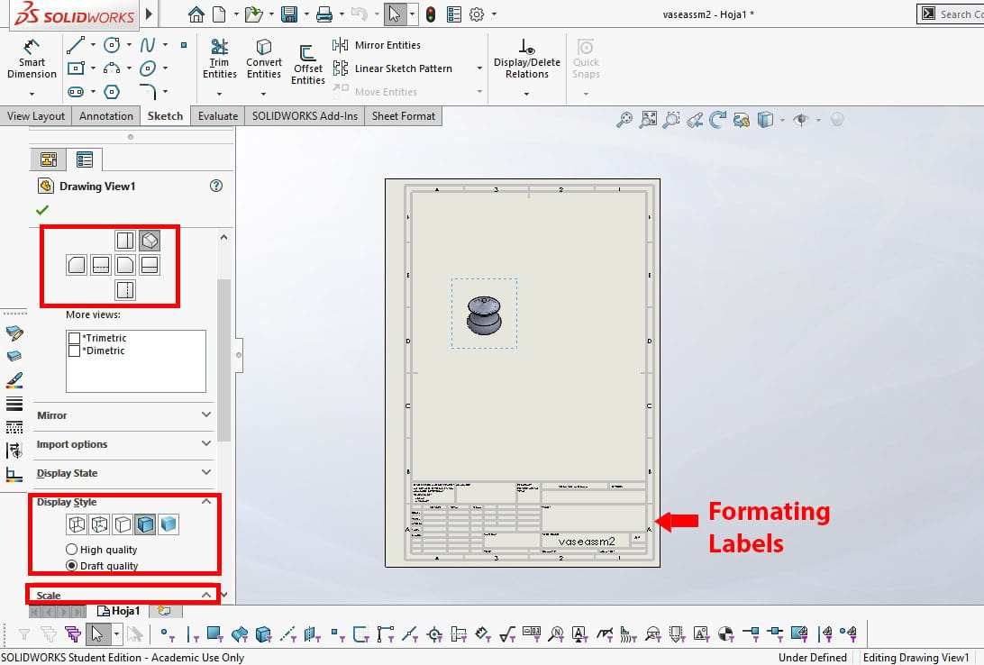
On the left side, on the PropertyManager, you get a series of options to toggle with. The first important one is Orientation, the second is Display Style, and finally, Scale.
- In our case, we set the orientation to “Isometric” and the display to “Shaded with Edges” because we’re only going to show the assembly without measurements first.
- We set the scale to “1:1”, as it would otherwise be too small.
- If you want to delete or modify the label of the format, you can right-click on the sheet and select “Edit Sheet Format”. We’ll delete the label lines this time as we don’t need them.
License: The text of "SolidWorks Tutorial for Beginners: How to Get Started" by All3DP Pro is licensed under a Creative Commons Attribution 4.0 International License.