SolidWorks 2021 vs 2020: The Differences

If you want to know about the next version of SolidWorks, we've got you covered. Read on to find out what SolidWorks 2021 will bring.
Performance on the Rise
It’s that time of the year again. No, not winter. It’s time to check out the new SolidWorks update!
Generally speaking, the 2021 update heavily concentrates on enhancing performance. As anyone who’s ever used it knows, SolidWorks consumes a lot of CPU memory, becomes slow with big assemblies, and puts the computer’s fans hard at work. With the new performance-oriented features, users will be able to work faster and more efficiently with larger and more complex designs. This improvement in graphics speed is considered by SolidWorks connoisseurs to be one of the best improvements of the update.
Still, perhaps the biggest news is the announcement of SolidWorks 3DExperience, which is a cloud design-to-manufacturing ecosystem to enable real-time collaborative work.
In addition to this, SolidWorks went through each of its environments and added small tools or made minor modifications which, put together, make for a more pleasant user experience. For SolidWorks 2021, a special emphasis was placed on fixing software performance results (SPRs). As a result, users who tried them can happily say that more issues have been resolved than ever before.
Now that you know the big picture, in the following sections, we’ll explore in detail the most relevant changes of SolidWorks 2021.

General Updates
Let’s start out with some broad aspects that have been a welcome improvement.
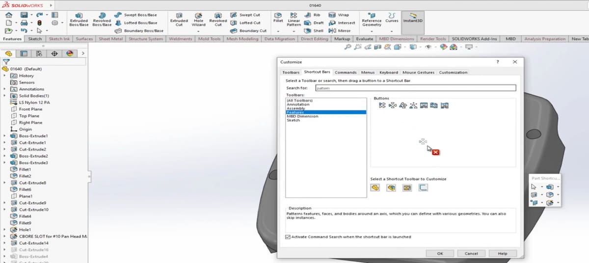
- UI customization: When working in the standard SolidWorks environment, all tools are available using the tabs at the top of the screen. Yet, it’s faster to work using the shortcut bar, which now in the 2021 version, can be customized. Moreover, you can customize any area of the user interface thanks to the new customization section, where you can choose functions and drag and drop them to any location.
- Less clutter: Now you have the ability to collapse the command manager, allowing you to reclaim as much screen space as possible. According to Stephen Petrock from Engineers Rule, this makes SolidWorks way easier to use because not only does it take away the clutter, it also gives you more space if you’re working on a small screen.
- Better redo: The redo functionality is more complete, allowing you to redo feature edits, where before you could only redo simple sketch changes. This means that, if you accidentally undo a feature, you won’t have to spend extra time recreating it.
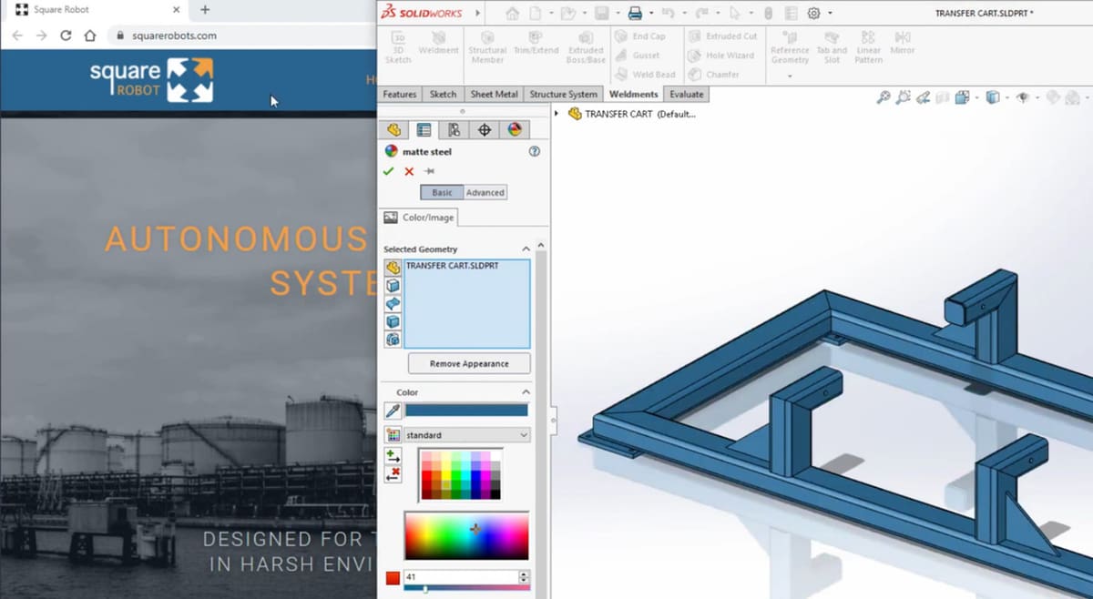
- Color dropper: Improvement to the dropper tool means there’s now an option for easily selecting colors that don’t exist in the pallet. With the update, you can select colors outside of SolidWorks (for example, from a web page). Simply minimize the size of the SolidWorks window and drag the dropper icon over any area outside of the screen, then the color under the dropper is applied to the section.
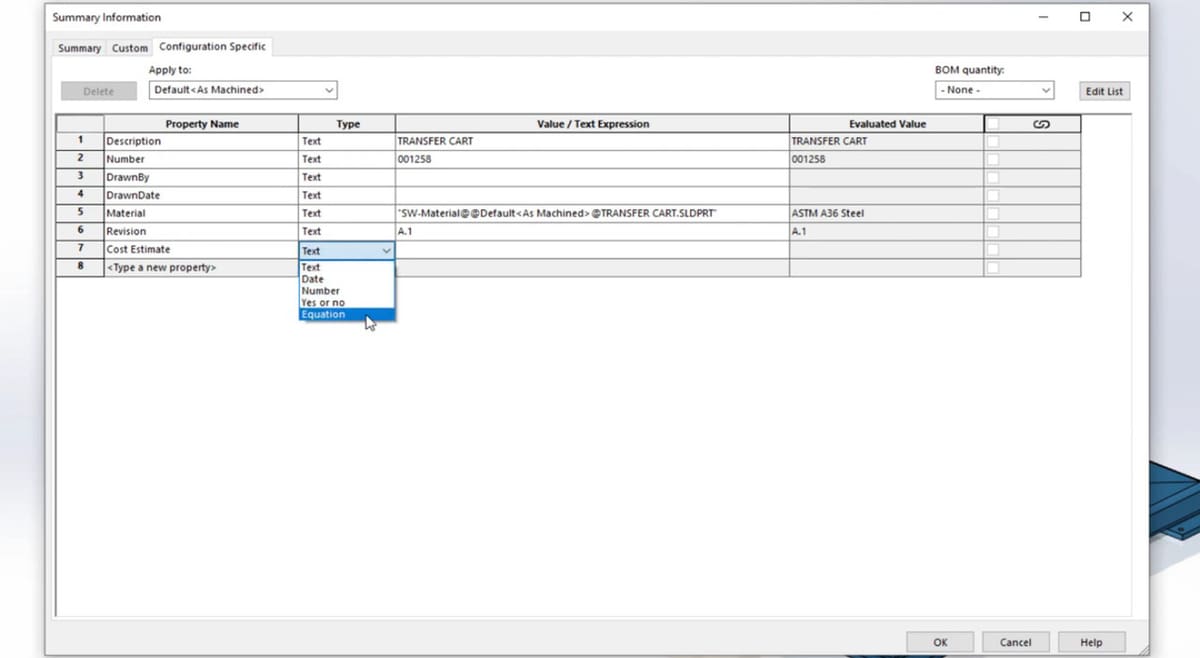
- Equation property: Equations can now be chosen as custom properties in the Summary Information Tab under property type. You can select the desired global variables, functions, or properties, which saves time when you need the same parameters for different parts. You used to have to create a new one each time, but now it’s a more convenient and efficient design process.
Note that custom properties available in the Summary Information tab, such as Author, Description, and Creation Date, can be leveraged automatically to populate title blocks in drawings or bills of materials and PDM.
Assemblies
As mentioned before, one of the main goals of the new update is to enhance SolidWorks’ performance. When it comes to assemblies, the improvements have made a big difference.
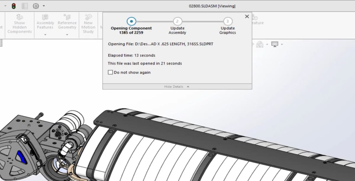
Faster Opening Times
Opening times for both resolved and lightweight assemblies have been improved. The larger the assembly, the greater the gain you will see when opening them in lightweight mode. And as expected, no matter where you look for reviews, everyone is raving about the enhanced performance this update brought.
Accessible Subassemblies
Subassemblies are now grouped in folders in the feature manager tree. Because of this, you can dynamically load those components as you need them, giving you access to the fully resolved assembly or part. This is useful because it prevents unnecessary loading of large assemblies, while also allowing you to access and modify the components you’re working on, as needed.
Simplified Configurations
Assembly configuration refers to the different positions or layouts you can have for the same assembly. Working on configurations is now also faster, both with switching between them and creating new configurations.
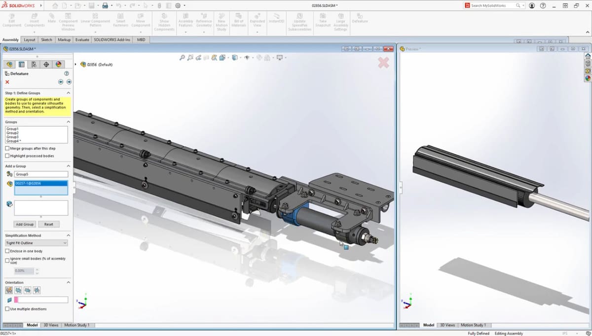
Silhouette Defeature
Configurations, together with a function called Silhouette Defeature, allow the user to create a simplified representation of a whole or partial assembly, whether to use for presentation or to protect intellectual property. First introduced in 2019, Silhouette Defeature allows one to simplify assemblies visually, and it also adds a performance boost in cases where the detail of the individual components isn’t necessary.
New in 2021 is the ability to save this simplified representation as a new configuration within the same assembly file, while previously it was necessary to manage a separate file that contains the simplified model. At the same time, in case you have to share it but don’t want other people to have the full model for propriety reasons, you still have the option to save it as a separate file by right-clicking on the component and selecting “Use Defeatured”.
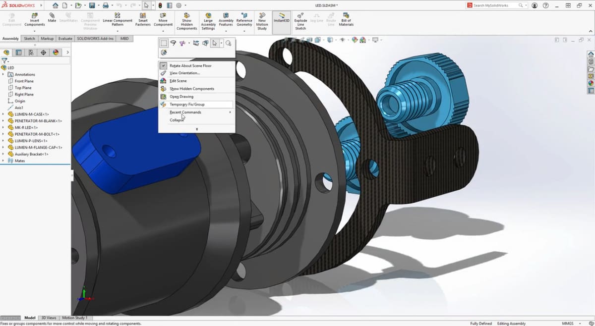
Manageable Mating
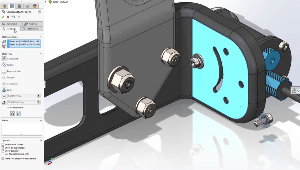
Modifications and additions were also made for mating. To start with, when you’re mating items, you’ll find a new streamlined property manager. Before, the different sections for types of mate options were arranged in a vertical menu in expanding sections for each group type.
In the 2021 version, these groups are arranged in tabs, making it easier to find the correct mate, especially as the assembly becomes heavier and the software slows down.
Slots
A big addition that seems simple but is actually major in regard to mating is the long-awaited slots. When creating mates for slots in 2021, you can now choose a default position. Likewise, there’s now the option to lock rotation slot mates, similar to concentric mates.
Previously, instead of using a default position, you would have to add an additional mate using a distance or something similar, to lock whatever part was mated with the slot into place. This meant that, to move around the part, you had to delete the mate and do the whole thing again (because of the weaker redo button). The locked rotation also makes it much easier to achieve different configurations for a drawing.
Circular References
A small though important addition that was made to mating has to do with the Performance Evaluation Tool, which has always been a useful resource to give feedback into areas that may present conflicts.
Part of what this tool does is verify references. References are the face, edge, point, or part that you add a measurement to in an assembly, and the Performance Evaluation Tool checks whether there might be conflicts.
In SolidWorks 2021, analysis and reporting of circular references were added, which is very important and previously lacking. This situation often appears in models with holes, which are a fundamental part of many assemblies (e.g. with screws), so being able to locate them properly is essential.
Recordable Interference Detection
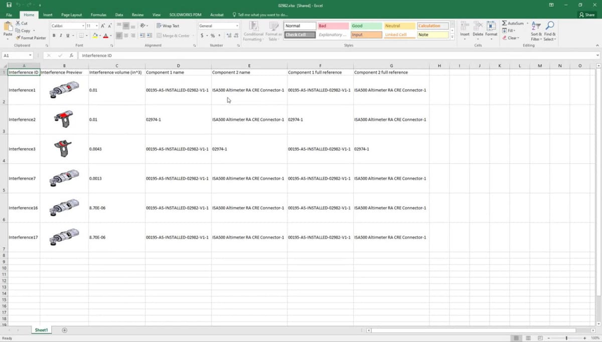
Interference detection, which is something that has only been improving in recent years, is a powerful tool to quickly find issues within a design, and it also went through improvements in this new version.
SolidWorks 2021 offers the option of, after running the diagnosis, saving these interferences in a spreadsheet. You even have the choice to capture a screenshot of each interference so that they can be shared and reviewed with any external collaborators.
Parts
There have been two significant upgrades when it comes to parts.
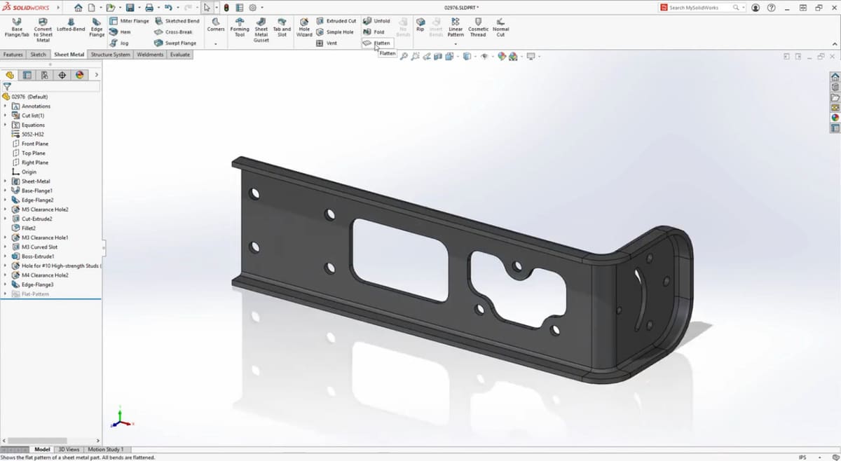
Edge Flanges
When working with sheet metal parts, you have the option to create curved edges. So far this has been limited to edges originated from planar faces, but in SolidWorks 2021, edge flanges can be created on curved edges that originate from non-planar faces, such as those in the bed area.
Edge flanges have an important effect in reducing deformation due to bending momentum caused by external forces applied perpendicularly to the surface. Of course, an edge can be flattened for manufacturing analysis, or as is true for any other curve in a sheet, you can change the direction, angle, and length of the flange.
Improved Export for Manufacturing
3MF, a file type standing for 3D manufacturing format, is often used, not surprisingly, when preparing a piece for manufacturing. After setting up aspects like textures, supports, and scales, you can generate the G-code or send the information to whatever process comes next.
SolidWorks already has the 3MF tool, however, it’s only able to export information regarding geometries, like dimensions, infill densities, or supports. With SolidWorks 2021, colors, textures, and transparencies are supported on export, to be later taken into account during the manufacturing process. Before, these features would have had to be manually added. This update finally makes 3MF a tool that’s on par if not better than others available in the market.
Weldment Environment
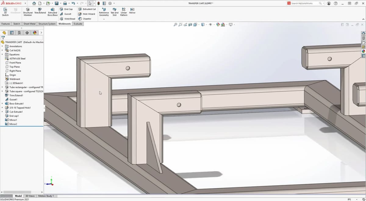
The Weldment Trim Extend Tool is used to weld two tubes to each other, with various options for corner types. The two end butt trims dictate how one tube trims with respect to the other, and the mitered trim bisects the angle between the two tubes, creating an equal angle miter trim.
Flush Miter
Up until recently, when two tubes were of different profiles, the equal angle miter couldn’t produce the desired result. To solve this, a new tool was added in SolidWorks 2021: the Flush Miter. It trims the tubes so that they meet flush, as the name indicates.
Drawings
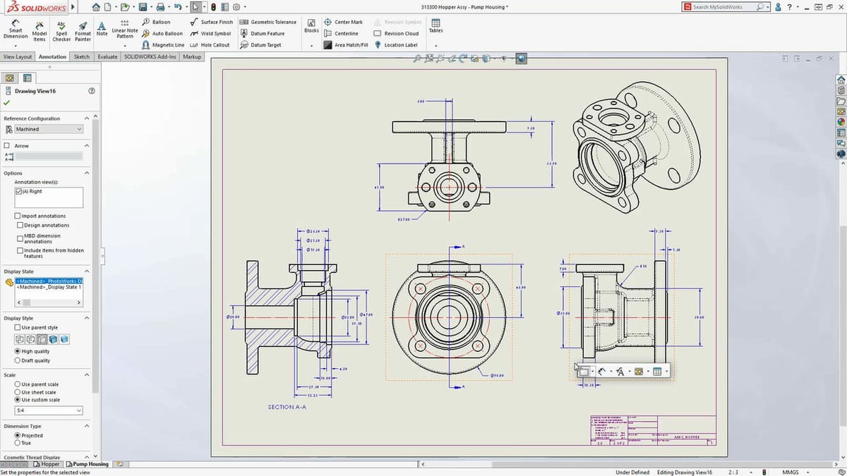
Detailing mode was introduced in SolidWorks 2020 to allow users to open massive drawings in seconds. Also in the 2020 version, an “Enhance graphics performance” option was added to assemblies to take advantage of high-end graphics cards.
Higher Performance Drawings
To improve drawing performance even more, this feature has been extended for the drawing environment, helping to avoid latency. This is especially apparent when zooming in and out of a drawing or when moving it around, which, as you may know if you have experience in the program, tends to be difficult because of how much later the movement shows compared to the real-time movement.
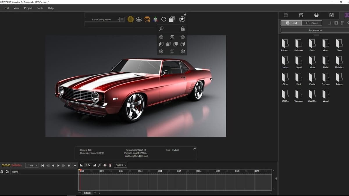
Visualize
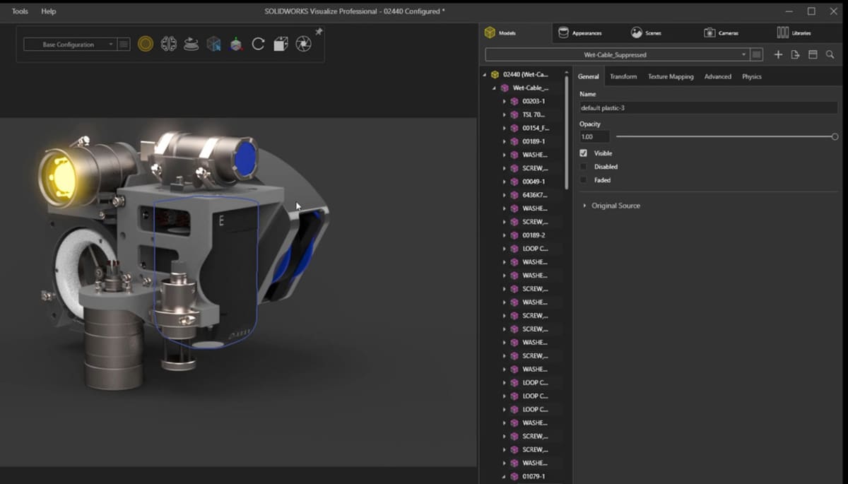
As explained by Go Engineer, SolidWorks Visualize is a rendering tool introduced to SolidWorks in 2016. It’s used to create photo-realistic images from CAD data.
Accessible Configurations
With previous versions of Visualize, you could only access the last-saved configuration when importing a model, which refers to the latest saved array of settings and view characteristics. In Visualize 2021, all configurations are now accessible from a drop-down menu.
Simplified Appearances
Applying appearances has been, from the start, a drag and drop process. In the 2021 version, this has been simplified even more. A single left-click will select the desired part, as always, and a double-click will take you to the menu to select the part’s appearance. This makes it easy to copy and paste appearances and even edit already existing ones.
Capped Section Cuts
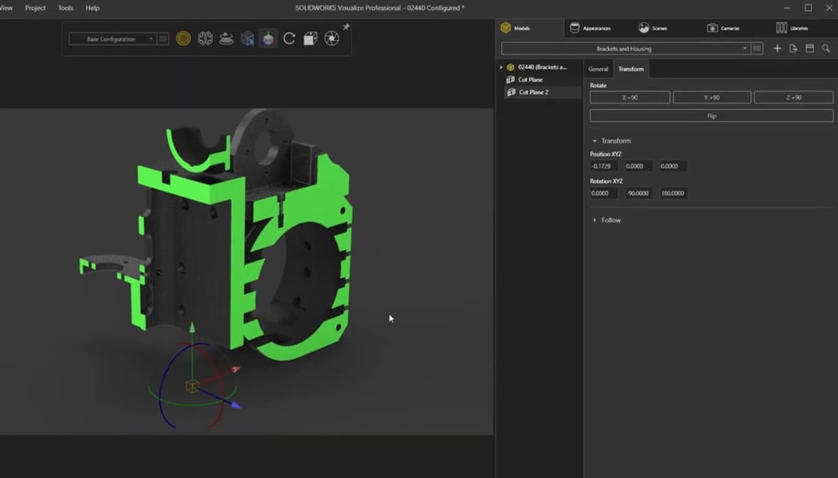
Visualize has supported section views in previous versions, but new in Visualize 2021 is the ability to add capping to these section cuts, along with modifying the capping color, which makes for eye-catching outputs. Plus, from the right-click menu, you can hide or show different combinations of these section cuts.
Displacement Map Densities
Another new addition to Visualize are densities for displacement maps. Displacement maps are a method of giving surfaces realistic finishes, so you can better view how a model will look when its actually manufactured. These maps are a great way to give complexity to a model, and until now, they’ve been a bit tricky to calculate.
In Visualize 2021, displacement map density can be defined to give really impressive results with much less work. This opens up the possibility of creating and rendering surfaces that are often skipped during the CAD design process due to their time-consuming complexity.
Artistic Renderings
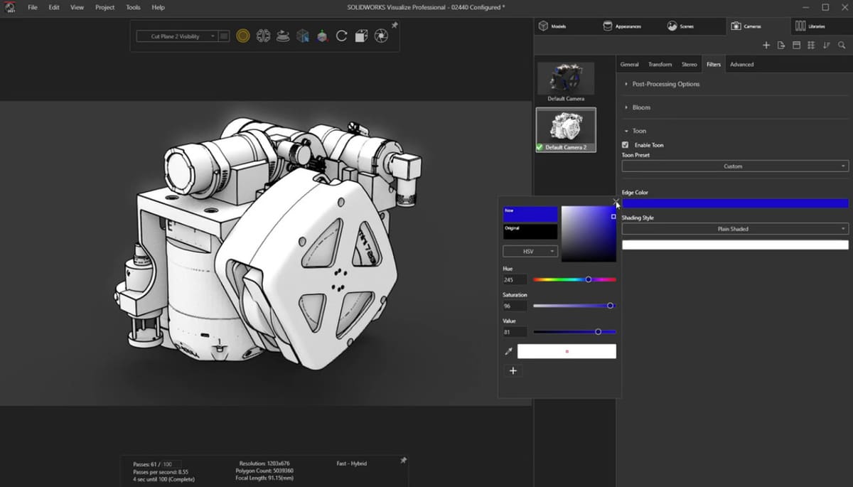
A great new feature in Visualize 2021 is the “Tune Camera Filter”. Sometimes, you’re not looking to show a photo-realistic visual rendering, so with this tool, it’s possible to easily give an conceptual, sketched look to a design.
Flow Simulation
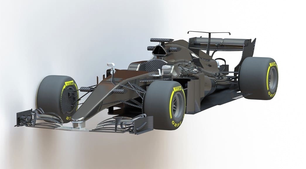
Flow simulation is a SolidWorks tool that allows the user to run computational fluid dynamic (CFD) studies. CFD is a computer-based tool for simulating the behavior of systems involving fluid flow, heat transfer, and other related physical processes using the finite element method (FEM).
This technique consists of making a mesh (composed of a number of discreet points, the “finite elements”) to analyze. With set parameters, the program runs and measures the properties of the part at each point of the mesh to create a general rule of behavior for the part.
SolidWorks has been working hard for years to catch up to other simulation software like Ansys or Abaqus, which have so far been at an advantage in terms of precision when it comes to simulation (though their modeling environments are far more limited in comparison to SolidWorks). SolidWorks 2021 expands the types of CFD problems that can be solved and improves project results processing.
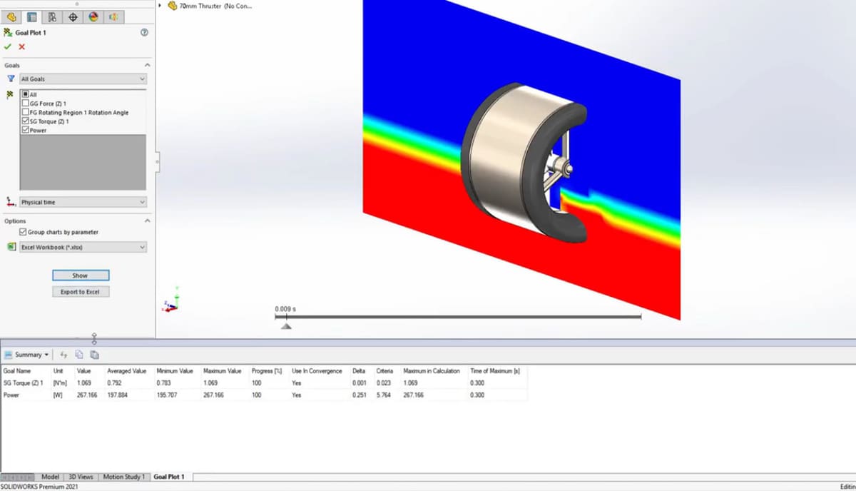
Rotating Feature
With Flow Simulation 2021, rotating regions can be combined with the “free surface” feature. This powerful tool can simulate the fluid driving motion of rotating components, such as pumps, turbines, or fans. From this, you can gain more insight into product performance.
Goal Monitoring
When you’re running a simulation, the variable outputs you want to track are called goals. By navigating to the history section of the goal plot, their values can be viewed throughout the duration of the study.
With Flow Simulation 2021, new columns provided in the summary table allow you to easily find the maximum or minimum value of each goal and when they occur.
Granted, this is like promoting that a car has power windows in 2020 – that is to say, it’s something that should be a given – but still, better late than never.
Flux Plot Type Grouping
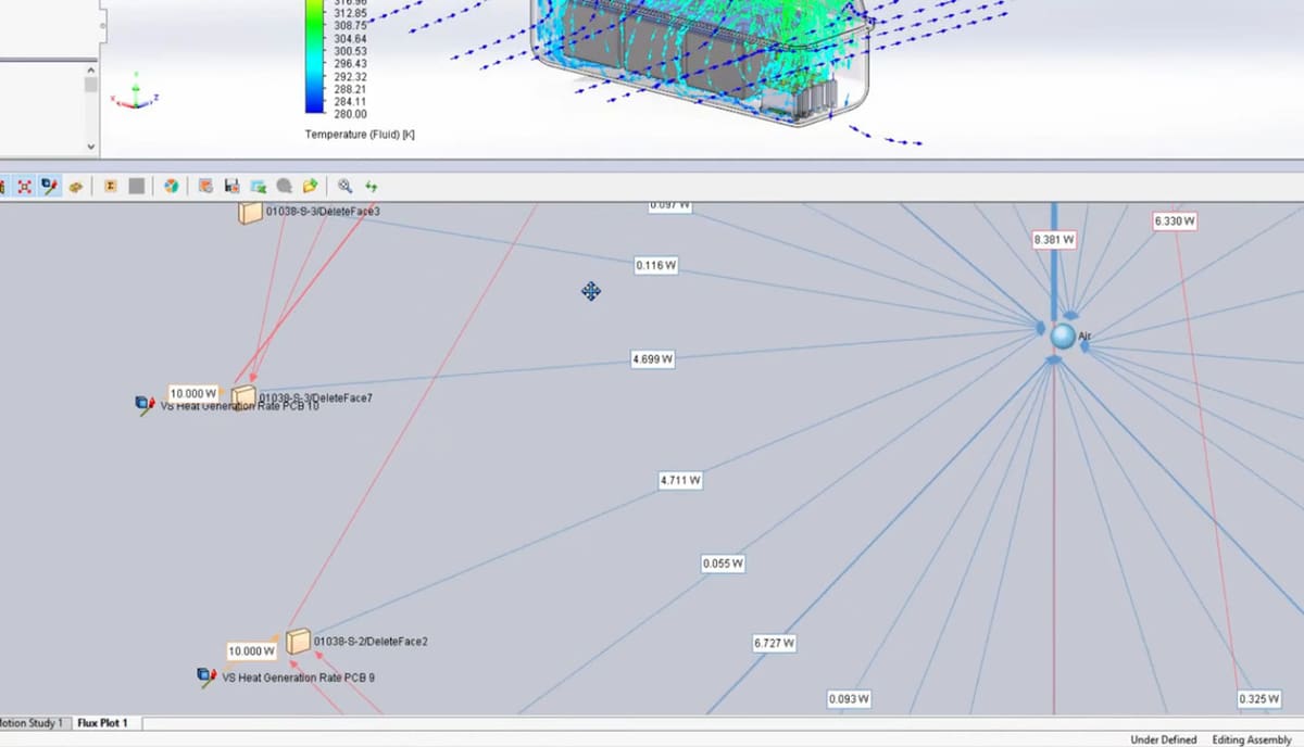
Another common application for SolidWorks flow simulation is heat transfer. A flux plot provides a graphic interface so you can easily understand the flux direction.
As mentioned before, a mesh is generated when conducting finite element analysis. In this case, a general rule of behavior for each property to be measured is created for the total part. If there’s conflict among the individual points measured in the mesh that prevents an output, the simulation can’t converge, meaning you have to check for mistakes as well as which parameters are under- or over-defined.
Now, in the 2021 version, you’re able to group all items in a plot by type so that you can quickly check the energy balance of the simulation and ensure that your study converges. If a simulation doesn’t, it won’t provide an output, which is a problem that often happens for common parameters. This makes the new group tool very useful and important.
Mechanical Simulation
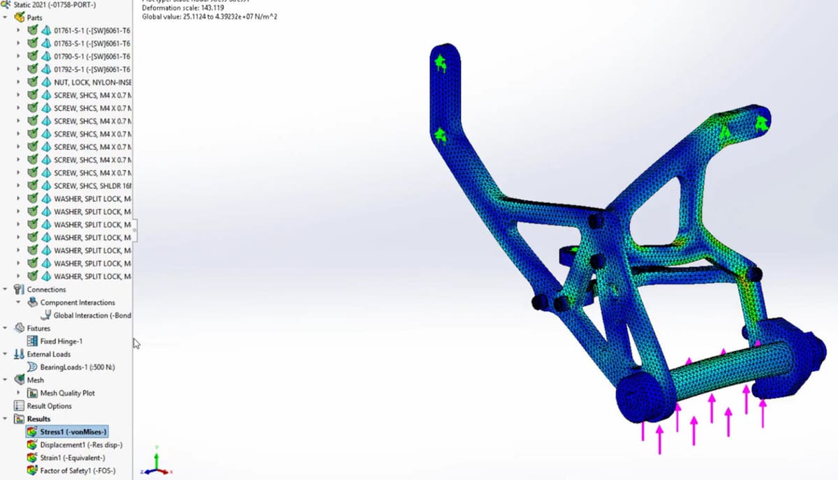
The Simulation tool in SolidWorks, not to be confused with Flow Simulation, is a tool destined for static simulation.
Static simulation is a method used to analyze the behavior (like deformations and strains) of solid components, in relation to forces and momentum, whereas CFD analyzes the behavior of these solid components when interacting with fluids.
Essentially, CFD analysis is much more complex and heavier than static simulation because the movement and thermal behavior of a fluid is much more dynamic than that of a solid part. As such, CFD needs many more elements in the mesh.
Better Performance
Now, mechanical simulation can be set up and run faster than in previous versions thanks to the added support for multi-core processing mentioned earlier and to multi-core meshing.
To reduce calculation requirements, hardware components are now set to use a draft quality mesh, while components that require greater precision can use a more complex mesh. The complexity of a mesh refers to the number of elements it’s composed of as well as the geometry with which they’re set up. (For additional information on meshing, you can check a helpful guide by SimulSoft.)
Again, SolidWorks is slightly lagging behind here, as compound meshing has long been a given in other simulation applications.
eDrawings
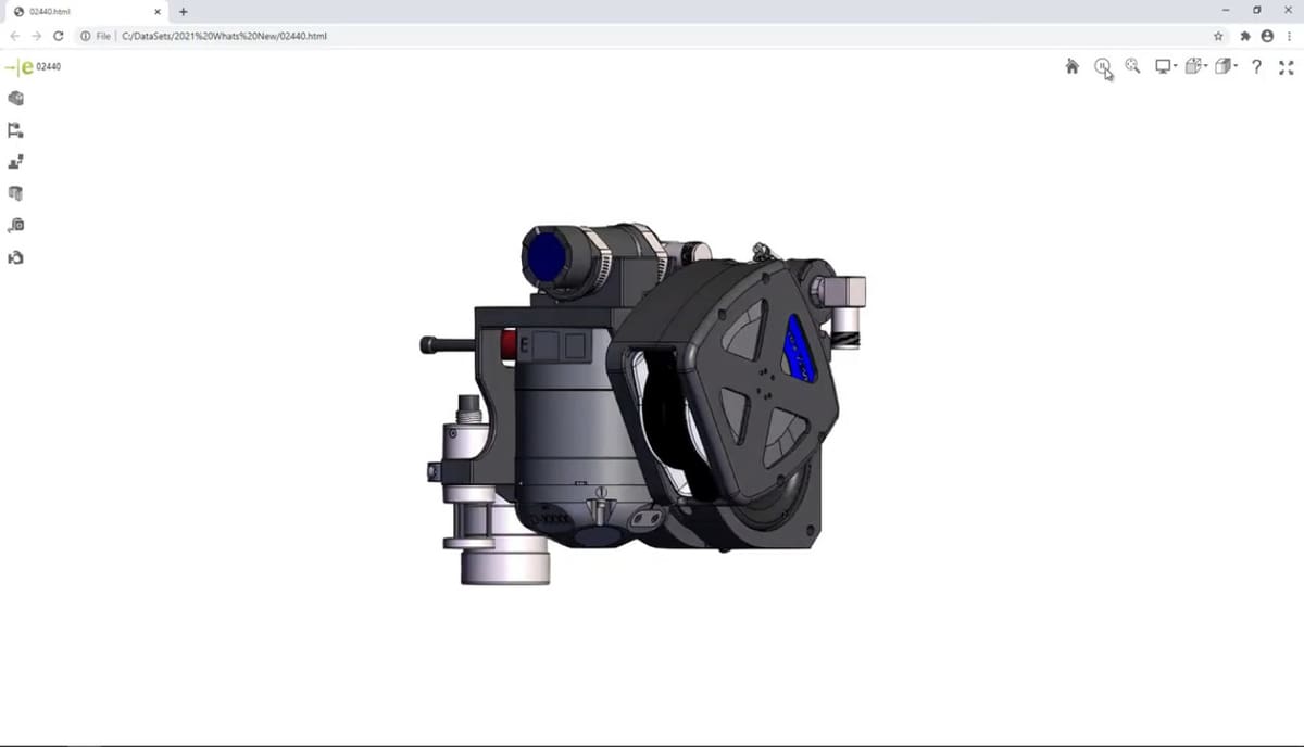
SolidWorks eDrawings is a useful way to share your 3D concepts while protecting intellectual property. It allows for movement and visualization but no modifications to the pieces or assemblies.
- Improved measurements: Commands like measure have been significantly improved. Though calculating the center-to-center distance of circular and cylindrical objects has always been allowed, you can now get the maximum and minimum distance between them. You’re also able to measure the normal distance between planar and cylindrical faces. Furthermore, you can use the measuring tools while in the web browser view.
- Individual translation and rotation: The 2021 version also allows you to individually translate or rotate parts without affecting the original assembly tree, whether inside the eDrawings environment or in the web browser view.
CAM
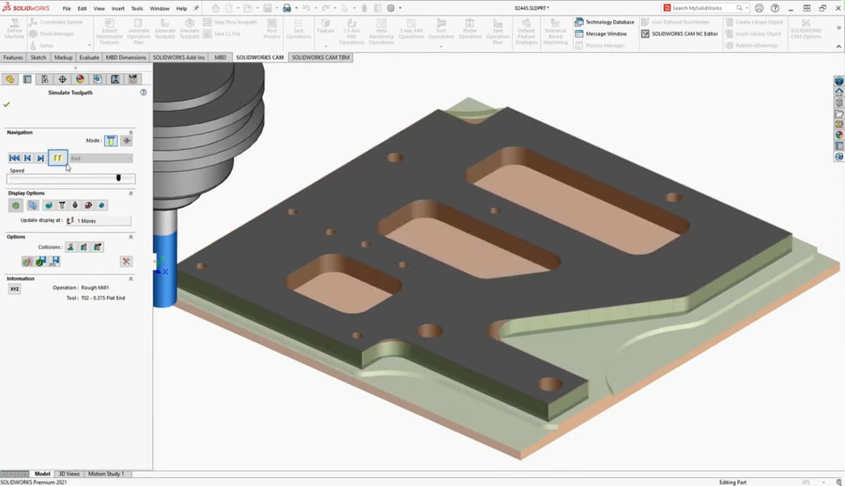
SolidWorks CAM is the manufacturing environment used to define the CNC process done by a machine. This process starts with a slab of wood called “Bounding Box” or “Stock”, which is then cut to achieve the final part.
Defined Stock Shapes & Sizes
With CAM 2021, a new option was added called “Predefined bounding box”, which gives you the ability to adjust the dimensions of the rectangular stock. Moreover, cylindrical stock can now be generated automatically for a bounding box.
These improvements are beneficial because you can generate the CNC code for the exact measure of stock you already have.
Final Thoughts
If you’d like to the official, complete rundown of all the new features in SolidWorks 2021, the SolidWorks’ YouTube channel is your best bet.
If you don’t have SolidWorks and are considering getting into it, we have several helpful comparison articles on Fusion 360, Inventor, AutoCAD, Solid Edge, and Creo.
Lead image source: Greg Tutor via Computer Aided Technology
License: The text of "SolidWorks 2021 vs 2020: The Differences" by All3DP Pro is licensed under a Creative Commons Attribution 4.0 International License.