OpenSCAD Tutorial for Beginners: 10 Easy Steps

Check out our OpenSCAD tutorial and quickly learn how to use this powerful 3D CAD modeling tool in 10 easy steps!
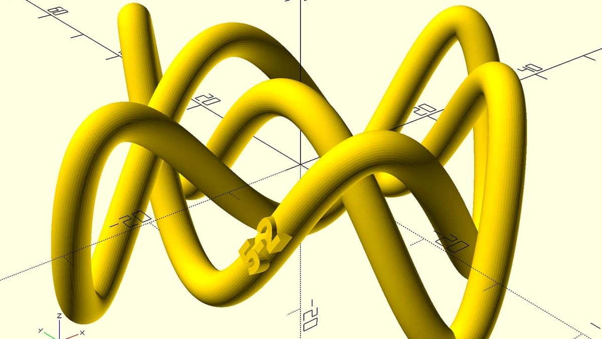
OpenSCAD (pronounced “open-S-cad”) is a popular, open-source application for modeling 3D objects. Unlike most other CAD tools, it uses scripts – a bit like using a computer program – to define shapes rather than manipulating objects directly on-screen using a mouse and keyboard commands.
The application is described as “the Programmers Solid 3D CAD Modeller,” but no previous programming experience is necessary. With just a little practice, even beginners can create complex shapes and animate moving parts.
OpenSCAD allows very precise shapes and structures to be defined. These can be made customizable using “parametric” models that allow for quick alteration of dimensions and other characteristics – as used by Thingiverse’s customizer tool and other design customization services such as Make with Tech’s.
On the downside, unless you can define it mathematically, OpenSCAD might not be the application for organic shapes such as desktop gaming miniatures. In such cases, free-form modeling tools like Blender have a distinct edge.
The use of OpenSCADs’ scripting language continues to grow and expand, and work is underway on several browser-based implementations as well as new rendering and visualization tools. So, it’s well worth learning. With that in mind, let’s get started!
User Interface
Let’s go over the first steps for using this flexible and powerful tool. We’ll download and install the software, and take some time to understand the OpenSCAD user interface (UI), as well as the basics of how it works.
Downloading OpenSCAD
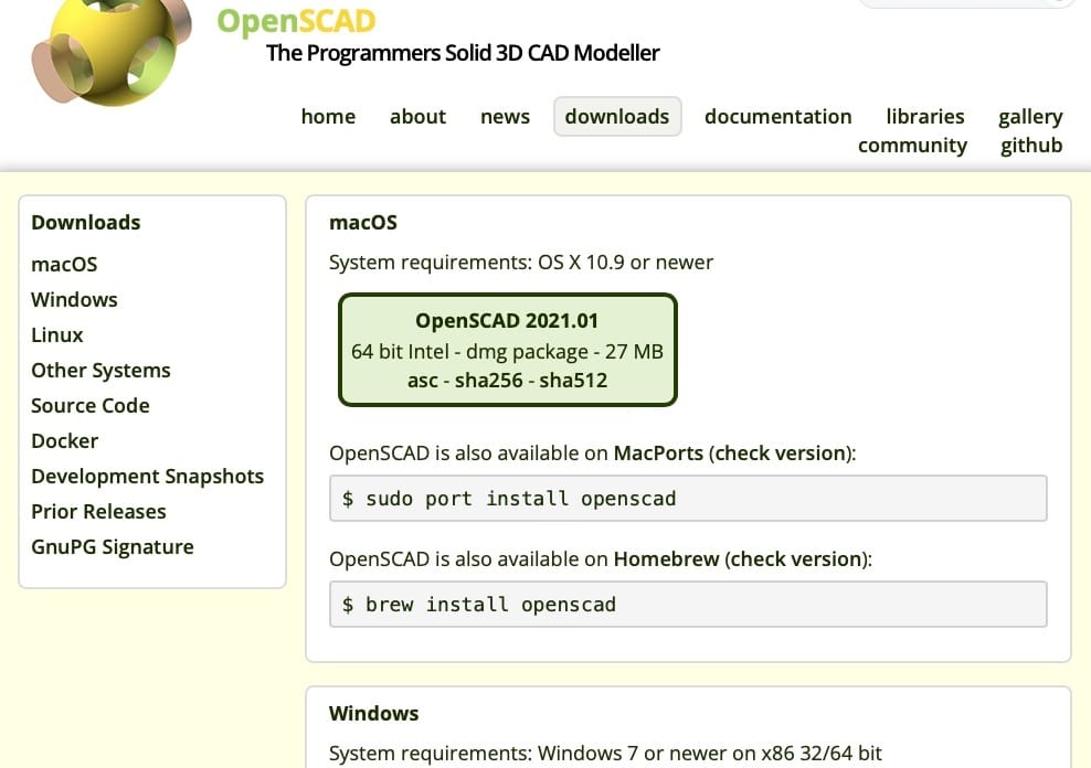
The latest stable version of OpenSCAD is available on the website’s download page. There are builds available for MacOS (including MacPorts and Home-brew), Windows (both 32- and 64-bit versions), and several Linux variants. Some of the computation in OpenSCAD is intensive, so a faster machine is useful for larger models. However, it will work well enough on any Mac running MacOS 10.9 and above or PCs with Windows 7 and above. There isn’t a version optimized for Apple Silicon yet, but it’s in the works.
A considerable amount of effort has also been done – as part of Google’s Summer of Code initiatives) – to improve model viewing and rendering. The latest development version of this, including all other recent improvements, is available further down the same page. The system requirements may be higher for these, so check the notices next to the download links.
Installation is easy:
- Select and click on the version appropriate to your operating system. This should download a .exe or .dmg file to start the installation process.
- Open the downloaded file and follow the instructions to install OpenSCAD. Mac users may have to acknowledge that this application is from an unrecognized developer in security settings.
Splash Screen
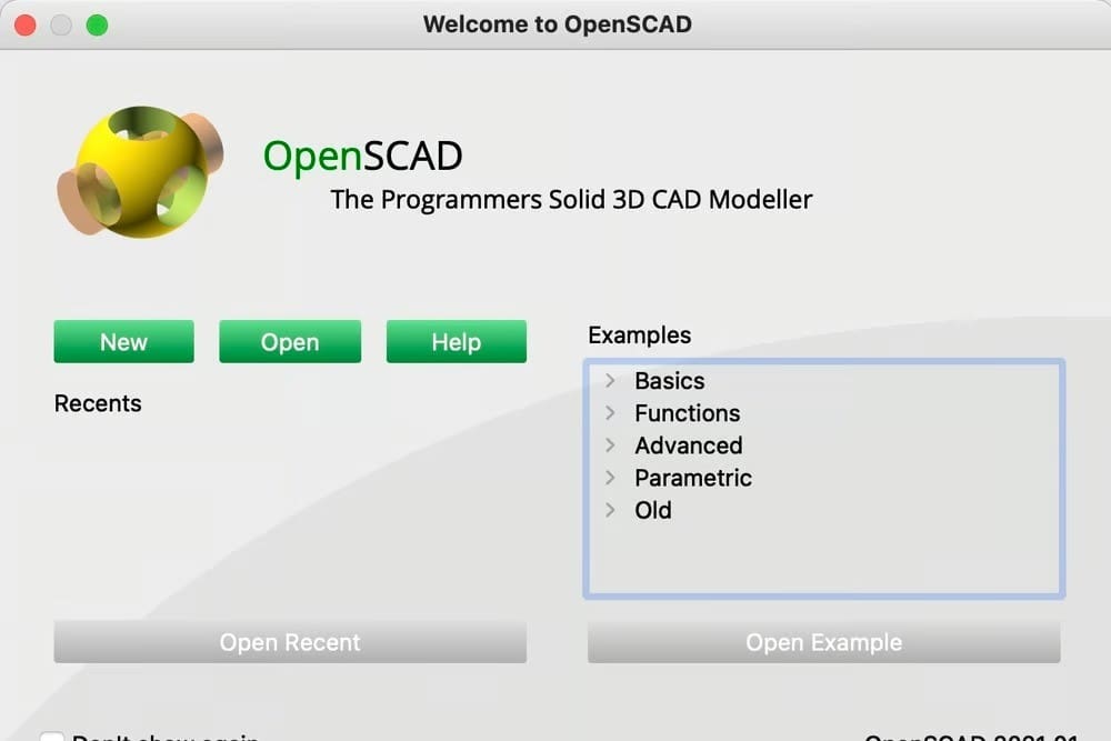
When you run the software for the first time, you should be met with the “Welcome to OpenSCAD” splash screen. From this screen, you can create a new file, open an existing one (your most recent files will also be displayed here each time you run the software), or open an example design. All of the included example files are well-written and highlight the key concepts behind how to use OpenSCAD.
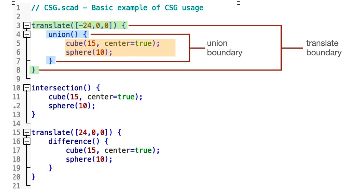
Later in this tutorial, we’ll use an example called “CSG.scad”. CSG stands for “Constructive Solid Geometry”, which is the technical name for how OpenSCAD works. Let’s open this file now so we can first explore the program’s UI.
- Navigate to the Examples box, and click on “Basics > CSG.scad”.
- Then, click “Open Example”.
After you’ve done this, you’ll be presented with the default OpenSCAD UI. If you’re new to coding, don’t worry if this screen looks complex. Take a quick look around at what is displayed. Later in the scripting tutorial, we’ll break it all down and make it simple to understand.
Windows & Menus
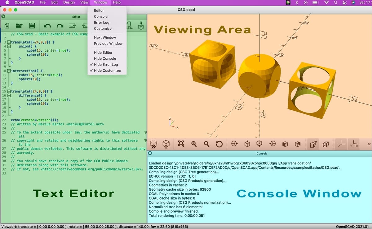
The interface is made up of the Viewing Area, which shows the design you’re working on and other windows that you can display, hide, or move around as you please. You can close individual windows by clicking either the ‘X’ at their top left corners or “Hide…” from the Window drop-down menu.
In the screenshot above, the Text Editor, Viewing Area, and Console windows are shown. On running OpenSCAD for the first time, it usually also displays an Error Window, but let’s close or hide that window for now.
Familiarize yourself with the basic options:
- Close or hide the Text Editor and Console windows using the ‘X’ or the hide option in the Window drop-down menu.
- Open these again using the Window drop-down menu.
- Experiment with changing their size and proportions by dragging the edge of each window and moving it as desired.
Text Editor
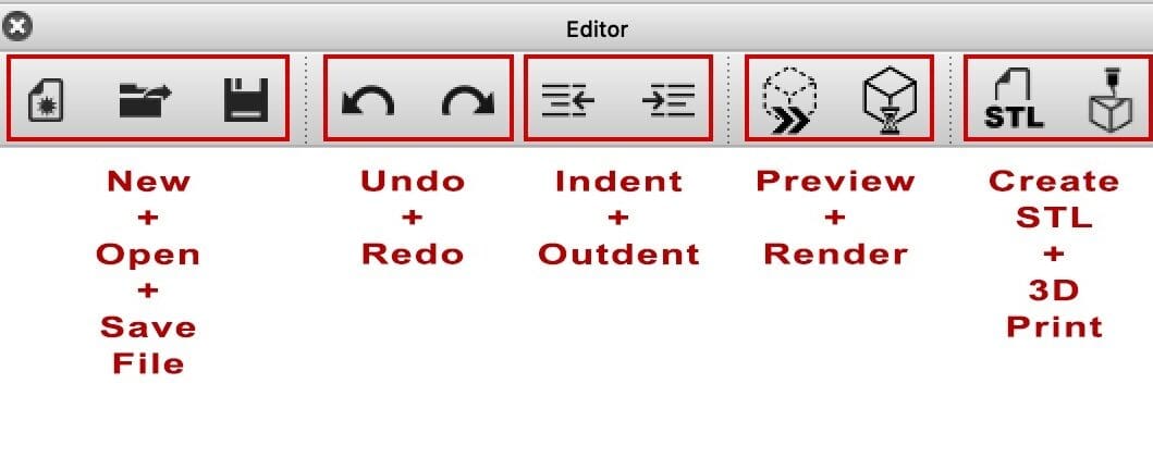
OpenSCAD code or scripts are entered using the Text Editor, and the resulting model will be shown in the Viewing Area. Most of the buttons in the editor are self-explanatory (e.g. New, Open, Save, among others). The interesting ones are the Preview, Render, Export as STL, and 3D Print buttons.
- Preview generates a quick model from the example script in the Viewing Area. This quick model shows the general idea of what it will look like, but it’s not the final calculated (or rendered) 3D model. Typically, you’ll use Preview after making any change to your OpenSCAD script to check that it works as you expected.
- Render tells OpenSCAD to calculate the final 3D model, which shows you an exact representation but takes much longer to generate than a preview. For very complicated cases, it’s not unusual for models to take hours to be rendered, but you won’t notice much of a difference with the shapes we create in the scripting tutorial below.
- Export as STL is a shortcut to a window that allows you to export your model as an STL file for 3D printing. Note that models have to be rendered before you can do this. You’ll also find options to export your model in other formats (3MF, for example) in the File drop-down menu.
- 3D Print is a shortcut to send your rendered 3D model to an online printing service or OctoPrint. By default, the printing service is Print A Thing, but others can be added in “Preferences” via the main menu.
The Text Editor is smart in that it can anticipate what script keywords are being entered, and it also helps format what is entered to make it easier to understand. There’s not much to experiment or play with at this stage, and we’ll see this in action in the scripting tutorial below.
Viewing Area
You can navigate around the Viewing Area by using a combination of mouse movements with left and right clicks and the Shift key. This will vary depending on your specific mouse and keyboard setup, but in general, the following applies:
- Rotate by dragging the mouse while pressing the left mouse button (LMB)
- Move by dragging the mouse while pressing the right mouse button (RMB).
- Zoom by using the scroll wheel or dragging the mouse while pressing “Shift + RMB”.
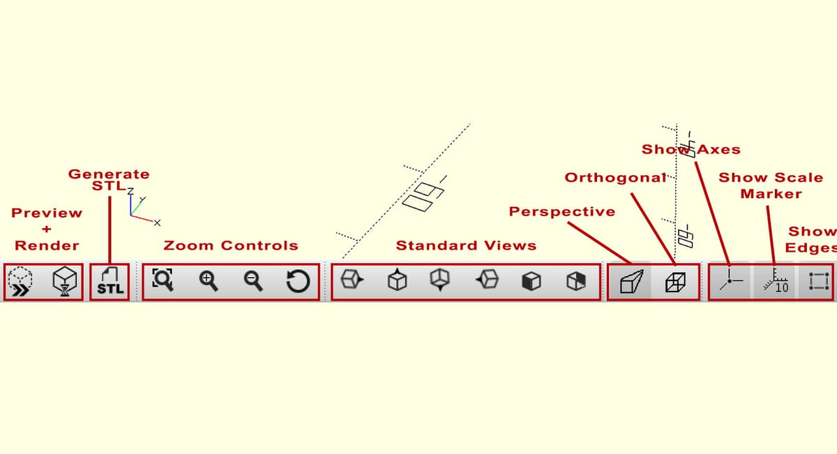
The Viewing Area also has several navigational shortcuts and other options implemented as buttons along the bottom of the window. First, you’ll find Preview, Render, and STL buttons, which duplicate those found in the Text Editor.
To the left of these are quick zoom controls including – from left to right – View All, Zoom In, Zoom Out, and Reset View, which is very useful if you get lost navigating around larger models.
These are followed by standard views that change the camera angle to look directly along the X-, Y-, and Z-axes.
The remaining menu buttons allow you to change other characteristics of what is displayed and may be useful in certain situations. For example, the orthogonal view is usually better for making mechanical models, while the perspective view is better for decorative models. Ultimately, it’s a matter of personal choice, though. Finally, you have options to switch on and off axis annotation as well as an option to highlight model edges.
Console
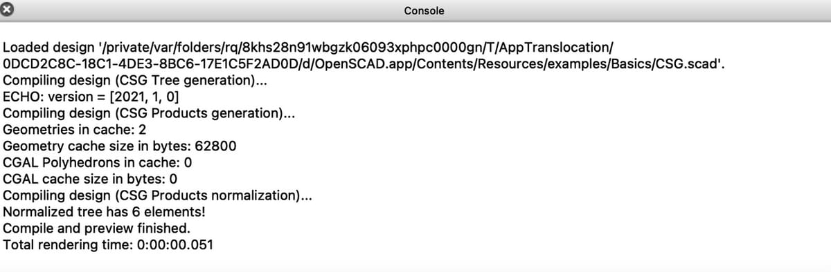
The Console normally appears below the Viewing Area and shows technical information regarding all of the software’s “under-the-hood” operations.
This can appear intimidating for rookies, but most of it can be ignored initially. It mainly becomes useful for more advanced users. However, it’s handy to identify when certain errors occur and to confirm that exported models have been saved properly. It also displays the contents of Echo statements (see step 10 below) that can be manually added to scripts to track their execution.
Nevertheless, have a quick look at what is displayed. It’ll give you an idea of what to expect as you become more advanced.
Scripting Tutorial
It’s time to get to grips with how to actually write an OpenSCAD script.
OpenSCAD scripts follow the conventions, or syntax, of the programming language C. Those familiar with that language should recognize the structure fairly quickly.
For those wanting to delve straight into more detail, there are many great online references available, including the OpenSCAD user manual and a very useful, concise “cheat sheet” for quick reference. For beginners, however, a precise understanding of the terminology is necessary at this stage.
So, let’s jump in!
Objects, Actions, & Operators
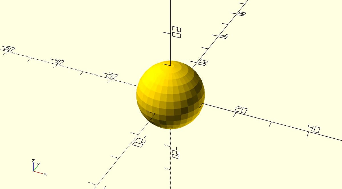
Before we get fully hands-on, let’s take a minute to understand basic OpenSCAD terminology. In simple terms, OpenSCAD works by defining “Objects” – typically in the form of 3D primitives such as spheres, cylinders, and cubes. Objects are created by “Actions”, which are then manipulated and transformed by various “Operators”.
For example, the Action sphere(10); creates a spherical Object with a radius of 10 units. It’s that simple! Note that OpenSCAD is unitless, so 10 could be 10 inches, millimeters, miles, or parsecs. However, for the majority of 3D printing applications, millimeters are assumed.
A number of OpenSCAD Operators apply various transformations to Objects to move, rotate, change colors, or combine multiple transformations to modify the resulting shapes in different ways. OpenSCAD scripts also include the other features found in programming languages, such as the definition of variables used for dimensioning objects and performing calculations as well as the ability to add comments to help others understand exactly what the script is doing.
Step 1: Basic OpenSCAD Code
Now, let’s look at the example we opened initially. We’ll be playing around and changing the code in this tutorial, so it’s a good idea to save your own copy and leave the original intact.
- From the main menu, select “File > Save As…”, then save the file as “CSG_tutorial.scad” at an appropriate location on your PC.
- If you can’t see anything displayed in the Viewing Area at this point, hit the Render button, which will display the Objects specified by the CSG_tutorial.scad script.
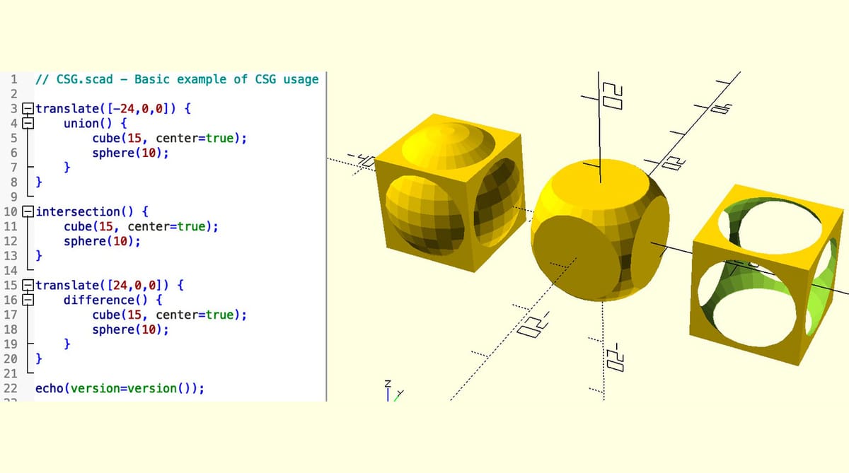
The example script generates three shapes, each of which combines a cube Object and sphere Object in different ways. The code for each of these is in three corresponding blocks, starting on lines 3, 10, and 15 respectively. We’ll walk through each of these blocks below to explain how they work.
Also note how the Text Editor helps make the script more readable by using different colors and how it also has little vertical black bars next to the line numbers that allow you to collapse and expand different parts, or blocks, of the script. This isn’t particularly useful with a small script, such as this example, but can be a life-saver with very long scripts.
Lines 3 to 8
Let’s look at the first block of code (from lines 3 to 8). In the center, you’ll see the following:
cube(15, center=true);

sphere(10);
The first line is an Action that specifies a cube with a side length of 15 units, centered on the origin of the X-, Y-, and Z-axes. The second Action specifies a sphere with a radius of 10 units. Spheres are centered by default.
The semi-colons after each line are very important. They tell OpenSCAD that the end of a particular Action has been reached.
Let’s play around with the code to gain some confidence in using the Editor.
- Change the dimension of the sphere on line 6 to ‘9’, then press “Preview” to see what happens.
- Change it back to ’10’ before we continue.
- Revise the code to
sphere(r=10);thensphere(d=20);
You’ll notice that the codes define a sphere in the same way as sphere(10);. All of them are equally valid ways to define a sphere.
Step 2: Union
The two Objects in the first block of code occupy the same actual space, so OpenSCAD will treat them as one by default. However, it’s good practice to say so explicitly; otherwise, unexpected behaviors can happen.
To tell OpenSCAD to recognize these as a single new Object, the Union Operator is used:
union() {

cube(15, center=true);

sphere(10);

}
Union will do exactly as its name suggests: It’ll create a union of all of the Objects within a “boundary” defined as everything inside the curly brackets.
Step 3: Translate
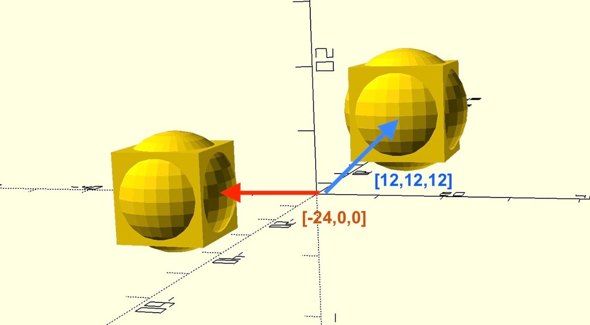
Next, the new unified object is shifted to the left along the X-axis. This is done using the Translate Operator, which moves all of the child Objects within its boundary a specified number of units along the X-,Y-, and Z-axes:
translate([-24,0,0]) {

    union() {

        cube(10, center=true);

        sphere(15);

    }

}
In this case, “[-24,0,0]” means move minus 24 units along the X-axis only. “[12,12,12]” would move 12 units along every axes – in other words, diagonally upwards.
Step 4: Intersection
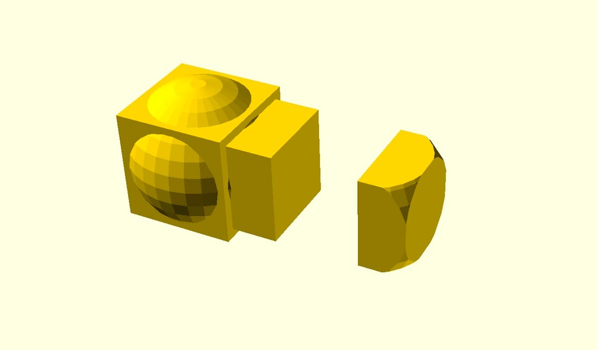
For the middle shape (specified by the second block of code lines 10 through 13), the cube and sphere are combined using the Intersection Operator. It produces a new Object that’s made from only the parts of all of the child Objects that overlap within its boundaries.
In other words, if any part of one Object doesn’t intersect with a part of all of the other Object(s), it’s removed from the final intersected shape. In effect, this Operator removes all of the parts that aren’t common to all of the Objects.
Try making a few changes to the dimensions of either the cube (line 11) or sphere (line 12) to see what effect this has. Before moving on, remember to return them to their original values. If you get lost, go to the File menu and select “Reload”, and you’ll return to your last saved version of the example).
Adding Objects
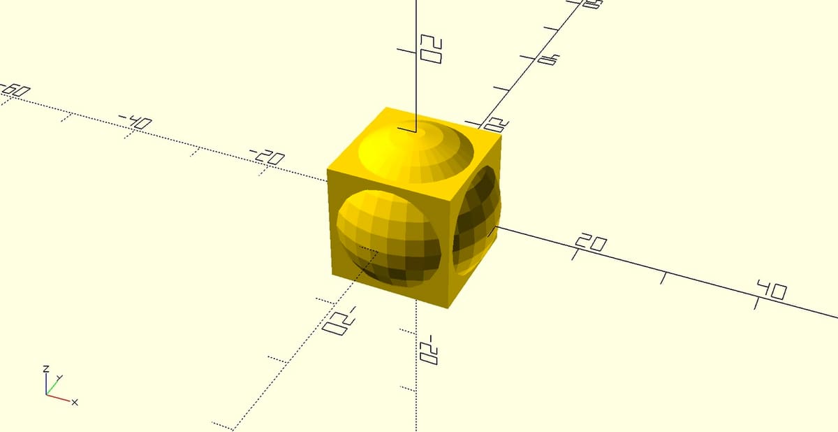
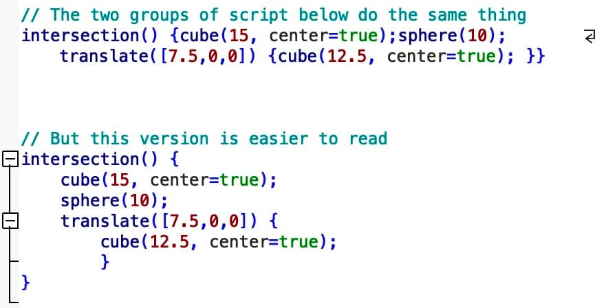
It’s also interesting to add another Object. Let’s add a slightly smaller cube offset by half of the existing cube’s width (using a Translate Operator), then we’ll see what happens.
In the Text Editor, position your cursor after the sphere action, hit return, and add the following to the line after the Sphere Action: translate([7.5,0,0]) { cube(15, center=true); }
The complete block should look as follows:
intersection() {

    cube(15, center=true);

    sphere(10);

    translate([7.5,0,0]) { cube(12.5, center=true); }

}
When you press Preview, you’ll see that the lefthand side of the original intersection is removed because that space is no longer shared with the new cube (see illustration above).
Step 5: Difference
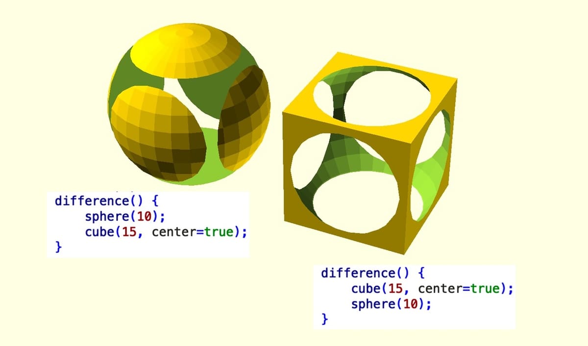
The last of our three examples is made using the Difference Operator, which subtracts an Object from another Object. It’s useful for creating holes and other spaces. Unlike Union or Intersection, Difference behaves differently depending on the order in which the Actions or Objects appear in the Operator.
Take a look at lines 16 through 20, then switch the order of cube (line 17) and sphere (line 18) within the Difference Operator. Notice how, in the original version of the code, the sphere is subtracted from the cube, but switching them around causes the opposite, as shown in the illustration above.
Basic Rules
Although simple, these examples highlight two very important aspects of OpenSCAD script. The first is that Operators are applied only to the Objects within its boundaries – in other words, only to those between the following curly brackets.
The second is that the sequence in which OpenSCAD executes Actions and Operators is sequentially, starting from the Operator that’s closest to the Object and working outward. So, in the first block of code from lines 3 through 8, the Union operation is performed on the cube and sphere first, then the new Object is moved by Translate.
Even when working with large, complex combinations of Operators and Actions, start at the innermost Object or Action, then work backward until you reach the uppermost Operator. As noted above, the Text Editor can help identify those Objects that are most deeply nested. See the vertical bars next to the line numbers.
Syntax
When you typed in the new Translate line in step 4, you may have noticed that it automatically indented. This isn’t necessary for the OpenSCAD script to run, but it makes it much easier to read. So, at this point, it’s worth saying something about syntax, the rules for entering a script that can be understood by OpenSCAD.
Mandatory (or critical) syntax is absolutely necessary for the code to run. If it’s missing or written incorrectly, OpenSCAD will throw an error message when you try to Preview or Render the model. We’ve already seen the two key examples of mandatory syntax:
- Every Action statement must end with a semicolon. This includes the Actions that make Objects as well as the Actions that define Variables (see step 9 below).
- Curly brackets (a.k.a. braces or curly braces) indicate the boundaries of an Operator statement. When working on a complex OpenSCAD project, it can be easy to lose track of these. However, when you click on a brace, the Text Editor highlights its matching partner, which makes things a little easier when things get complicated.
Optional (or non-critical) syntax makes your code much easier to read and edit. Examples include the following:
- Indentation is usually increased when you’re within a new Operator and decreased when the Operator is finished. As previously noted, indenting is not actually necessary for OpenSCAD to run, but it keeps the code looking neat and tidy. Press “Shift + Tab” to indent or outdent respectively. Alternatively, you can use the Indent and Outdent buttons at the top of the Text Editor.
- Line breaks and spaces are not strictly necessary for OpenSCAD to run either. In theory, you could enter any block in this example as a single line, and the code will still work. However, taking out line breaks and spaces makes the code very hard to read.
- Comments are denoted with a pair of slashes (“//”). Everything following these is ignored by OpenSCAD until the beginning of the next line. The very first line of this example is a comment, for example.
Other Operators & Features
Now is a good time to explore a few more features of OpenSCAD. We’ll make some simple changes to the example code and look at three cases.
Step 6: Specifying Shapes
First, let’s experiment with Actions that specify shapes. We’ve looked at simple versions of sphere and cube, but the cube Action can define any rectangular shape.
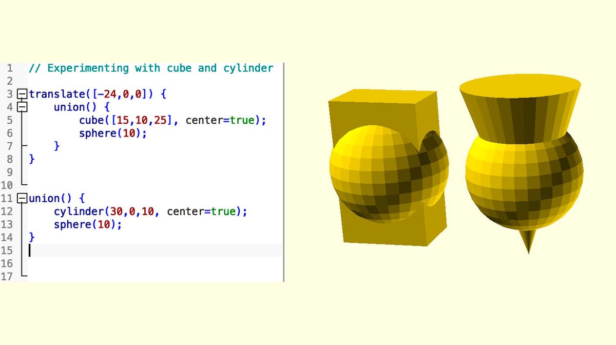
- Replace the cube Action with
cube([15,10,25], center=true); - Press Preview. This should reveal a cuboid with dimensions of 15, 10, and 25 in the X-, Y-, and Z-axes, respectively.
- If you feel confident enough, replace the cube Action with the cylinder Action, then experiment with the parameters which specify it (including turning it into a cone). Refer to the cheat sheet for the relevant scripts.
- Change the script back to its original dimensions before continuing.
Step 7: Changing Resolution
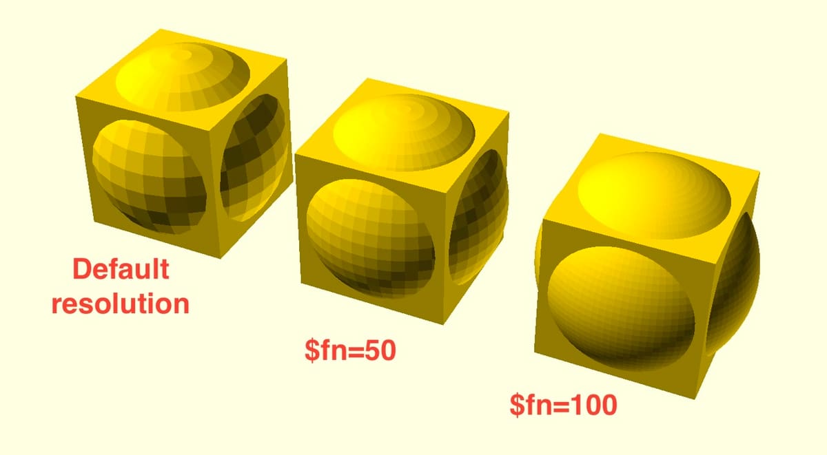
You may have noticed that the rendered sphere is not very smooth. This is because OpenSCAD defaults to a low resolution in order to keep processing time to a minimum. However, you can select higher resolutions when you want, either for individual Objects or for the entire model.
This is done by using the “$fn” value. This defaults to around 30 and defines how many fragments are used to make up a shape. Values over 128 are not encouraged, and anything over 50 can add considerable time to final renders.
- In the first block of code, change
sphere(10);tosphere(10, $fn=50); - Hit Preview. You should see the resolution of the sphere improve considerably.
- To improve the resolution even further, change it again to
sphere(10, $fn=100);
Note that you can do the same for each sphere and even uses different $fn values. There’s also a way of defining $fn for the entire script, which we’ll explore below in step 9.
Step 8: Adding Color
Adding color can be useful to make models more realistic or to make certain elements stand out in the Viewing Area. Colors can be defined in different ways in OpenSCAD: as RBG values, hex values, or from a predetermined set.
A Color Operator is added before the script’s Actions. While it isn’t an Action itself, it modifies an Action. So, there’s no need for a semicolon after it.
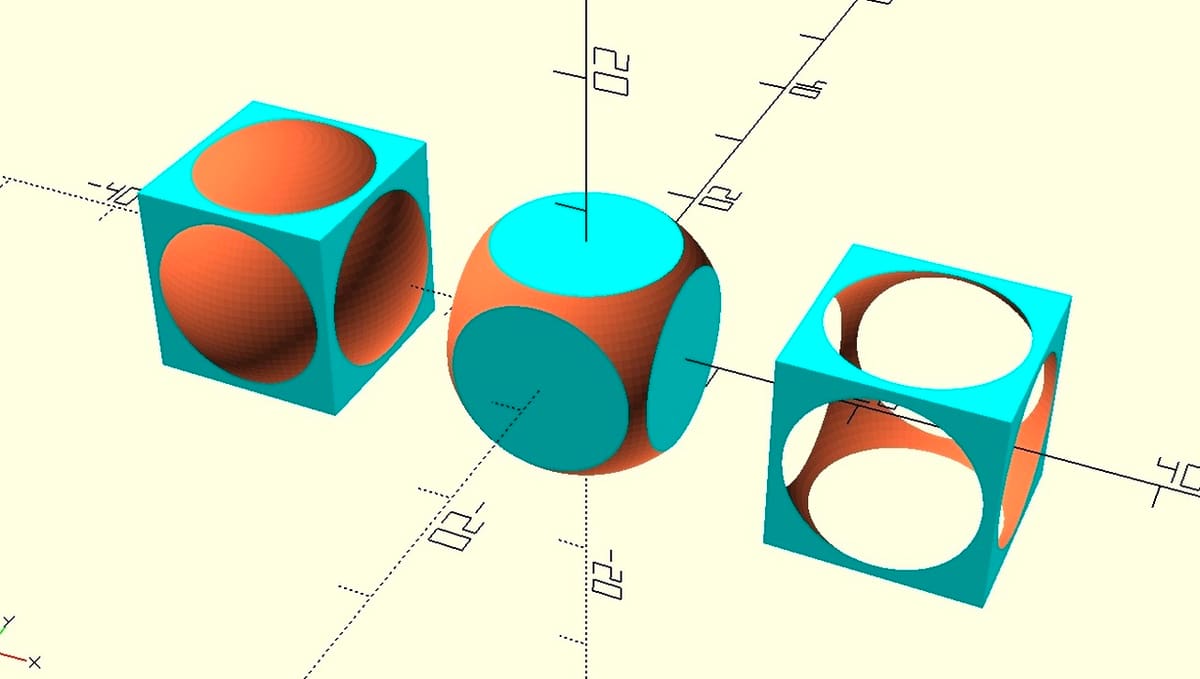
To demonstrate how to do this, let’s modify our example so that the cube is colored “cyan” and the sphere is changed to “coral”. Add the Color Operator before the Actions used to define the cubes and spheres as shown below:
translate([-24,0,0]) {

    union() {

        color("cyan") cube(15, center=true);

        color ("coral") sphere(10);

    }

}

intersection() {

    color("cyan") cube(15, center=true);

    color ("coral") sphere(10, $fn=100);

}

translate([24,0,0]) {

    difference() {

        color("cyan") cube(15, center=true);

        color ("coral") sphere(10, $fn=100);

    }

}
Note that the colors only appear in Preview mode. Rendering images ignores colors in the Viewing Area but still exports that information if the export format supports this.
Parametric Design
Now that we’ve walked through the CSG.scad example and become familiar with both the user interface and the basic entry of scripts, let’s talk about parametric design.
In parametric design, the user can change certain elements of the model, and the rest of the design adapts to accommodate these changes. For example, if a design features multiple screw fittings of a certain size, these could all be changed to another size without sifting through and changing each separate occurrence. Alternatively, parametric design can be used to quickly change the number of repeating features on a model.
The foundation of parametric design is the use of variables instead of static or hard-coded values distributed throughout our code.
How does this work? Let’s take a peek!
Step 9: Variables 101
So far, the size (and colors) of the cubes and spheres are defined in each separate block within our example. If we want to change the radius of all of the spheres, we need to do this three times. This may not seem to be an issue, but imagine if there were references to 10 or more spheres! You’d have to find and manually change each, which is both time-consuming and error-prone.
A much neater and more professional way to do this is to define the radius only once as a variable. A variable is created using a type of Action statement, and after it’s defined, we can use the variable throughout the script instead of a number. Variables can be defined either at the top of the script or anywhere above the first Operator or Action that uses it.
- In our sample code, add the following line near the top, which begins on line 3 in our example:
sphere_radius = 10;. This creates a variable named “sphere_radius” and makes it equal to 10. - Next, replace all the instances of
sphere(10);withsphere(sphere_radius); - Hit Preview. There should be no change to the image in the Viewing Area, but if you now change the value of sphere_radius to something else (say 11 or 9) and then press Preview again, you’ll see an immediate change to all three shapes.
Variables Galore
You can now extend this idea and create variables to replace all other values, including the length of the cube and the colors we added above. You can also specify the resolution to be used in previewing and rendering all of the shapes.
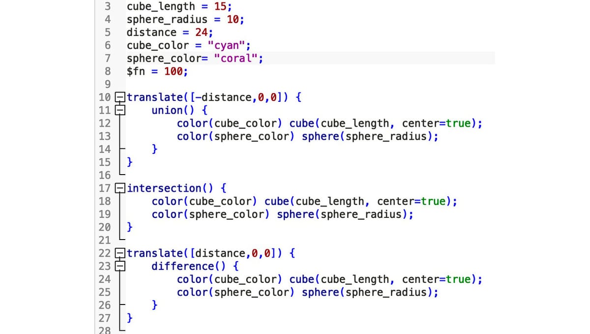
- Modify the code to look as follows:
cube_length = 15;

sphere_radius = 10;

separation = 24;

cube_color = "cyan";

sphere_color= "coral";

$fn = 100;

translate([-separation,0,0]) {

    union() {

        color(cube_color) cube(cube_length, center=true);

        color(sphere_color) sphere(sphere_radius);

    }

}

intersection() {

    color(cube_color) cube(cube_length, center=true);

    color(sphere_color) sphere(sphere_radius);

}

translate([separation,0,0]) {

    difference() {

        color(cube_color) cube(cube_length, center=true);

        color(sphere_color) sphere(sphere_radius);

    }

}- Hit Preview. Again, there should be no change to the image in the Viewing Area, but you’re now able to change most of the parameters defining the design.
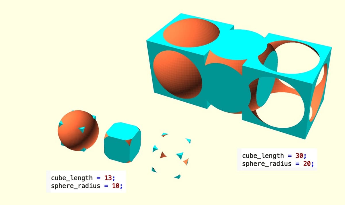
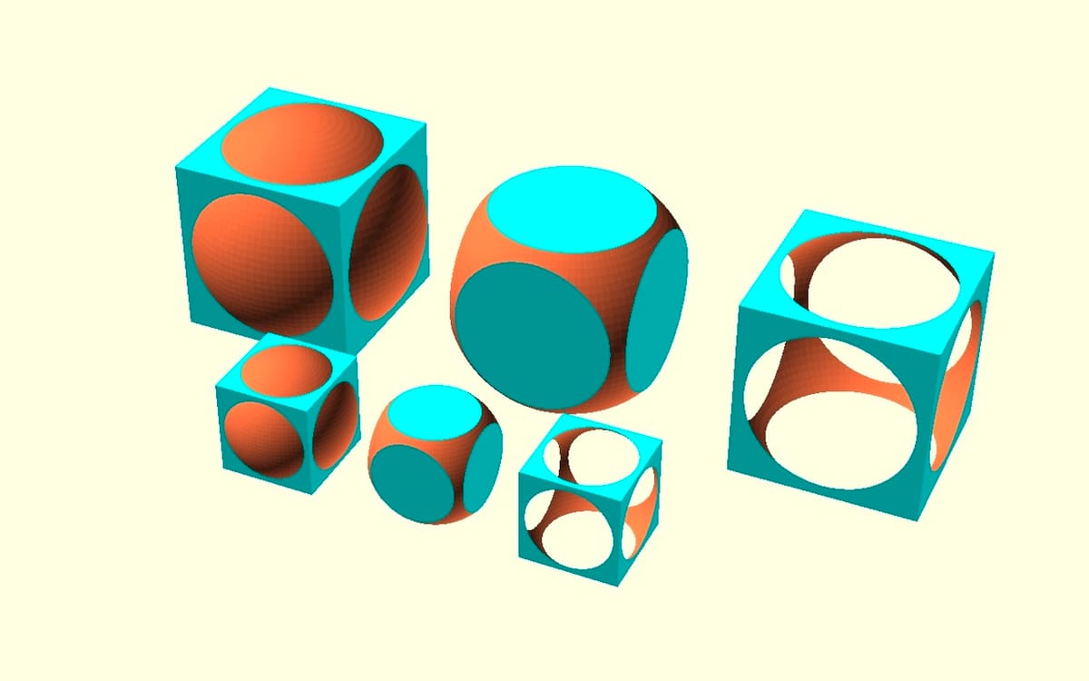
- Modify the values associated with the cube and sphere dimensions to see how the relative proportions of each of the three shapes changes (as illustrated above). For example, try the following:
cube_length = 13; sphere_radius = 10; - Next, change them as follows to retain the original shape proportions but double their size:
cube_length = 30; sphere_radius = 20;
With the last modification, the new shapes overlap (see illustration). This can be fixed by increasing the size of the separation variable, but we can do better than this. We’ll show you how in the next section.
Step 10: Variables for Parametric Design
In the previous example, we saw that attempting to scale up the whole model by doubling the size of the cube length and the sphere radius caused the three shapes to overlap. A simple fix would be to double the size of the separation variable, too (e.g. separation = 28;). However, good parametric design minimizes the number of variables to change.
In this case, there’s a way to relate all of the key dimensions to just a single variable. As with all parametric designs, a simple calculation is required. In our example, we can see that the sphere radius is two-thirds of the cube length, and the separation is in turn 2.4 times the sphere’s radius.
We can calculate these in OpenSCAD. Professional engineers might cringe at this example, but it’s only to illustrate a point!
- In the Text Editor, delete the following lines:
sphere_radius = 10;

separation = 24;
- Replace the above with the following, which includes example comments to remind future readers what’s going on:
// The model is kept in proportion based on cube_length = 15;


// Sphere radius and share separation are now calculated, defined variables

sphere_radius = cube_length * (2/3);

separation = sphere_radius * 2.4;


// The following lines echo the defined variables on the Console

echo("Sphere radius = ", sphere_radius);

echo("separation = ",separation);- Hit Preview. You should find that the model doesn’t alter visibly.
- Change the cube length to any other value (try ’30’), then press Preview again. You should find that the entire model scales up or down in the same proportion.
Those of you who have read ahead may realize that there’s a Scale Operator in OpenSCAD that we might also have used, but that wouldn’t have been a useful example at this stage!
Here’s a challenge for you: The illustration above shows the original dimensions of our example model and also one that’s twice the size in the same view. Can you figure out how to modify the code to achieve this?
Final Thoughts
Now that you’ve mastered the basics, it’s time to start making some designs of your own. Read over the documentation and play around with the different Operators and Actions that OpenSCAD offers. There are many rich seams of information online that include easy-to-follow examples.
In particular, we recommend exploring the following:
- OpenSCAD’s online library of examples
- Their gallery of examples, from simple to very complex
- A beginner’s quick start video by mathcodeprint, which augments the examples we used here
These will get you started on trickier concepts – such as Vectors and Loops – and propel you down the path toward designing more complex models and even animated simulations.
And of course, practice makes perfect. Just sit yourself down and try designing something you can 3D print. You’ll surprise yourself with what you can do on your first try.
License: The text of "OpenSCAD Tutorial for Beginners: 10 Easy Steps" by All3DP is licensed under a Creative Commons Attribution 4.0 International License.