LibreCAD Tutorial for Beginners: 8 Easy Steps

LibreCAD is popular, free, and open-source 2D CAD software. Get started with this easy-to-follow LibreCAD tutorial!
LibreCAD is free and open-source 2D CAD software. It’s a great alternative to AutoCAD because it shares its more popular functionalities while remaining free, making it accessible for start-ups and freelancers with a reduced budget. Its file formats are compatible with AutoCAD and, when switching from one program to the other, it can still interpret layers and blocks, making it a great option even if you’re going to be communicating with an AutoCAD user.
Additionally, LibreCAD has entirely free CAM capabilities, as it actually started as a CAM project. It’s available for MacOS, Windows, and Linux, and it’s particularly popular with users from the latter given the incompatibility of other programs.
If you come from a previous 2D CAD program, getting started in LibreCAD may not be that hard. That said, some parts can be confusing, since the software uses different symbology in some aspects.
Not to worry, we’ve developed the following tutorial to start learning all the ins and outs of LibreCAD. But first things first: Let’s make sure we know what we’re looking at.

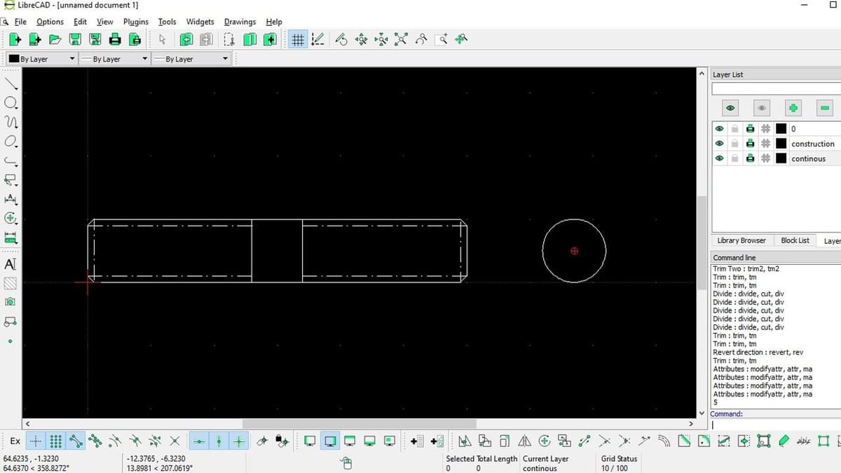
UI Overview
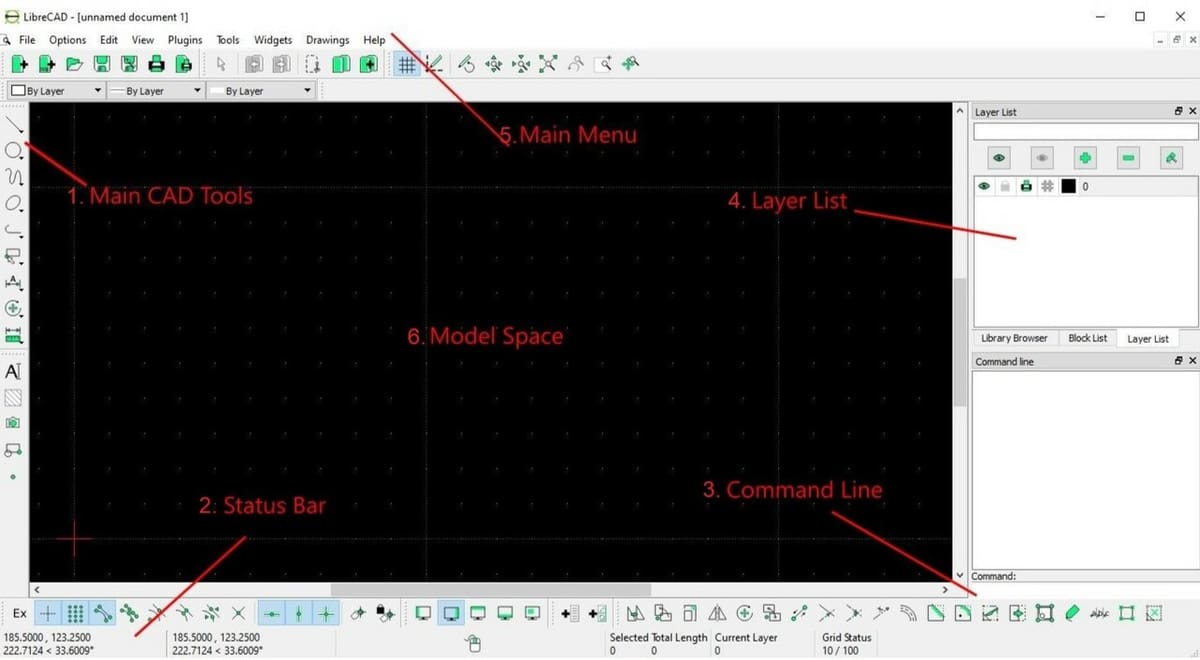
Before starting with the tutorial, we’re going to give you a brief rundown of the user interface (UI). This way, when we point to a specific tool, it’ll be easier to find.
- Main CAD tools: This is where you’ll find the most popular drawing tools, such as lines, rectangles, measures, splines, and more.
- Status bar: In this bar, you’ll find information about the coordinates and the current context of the cursor.
- Command line: As the name suggests, this is where you input commands. The square above the command line shows the command history.
- Layer list: This is where all existing layers can be found, and above that are the layer tools, with functions such as adding, removing, and modifying layers.
- Main menu: Here you’ll find the typical app menus, like File, Edit, and View. An important tab of this menu is “Widgets”, where you can enable and disable more toolbars. You may notice that in this UI image there are two extra toolbars above the Status bar; these are the “Snap Selection” and “Modify” toolbars. They’ve been enabled in the Widgets menu and will be explained later on.
- Model space: The area where we visualize the model, known in most software as the viewport.
Tutorial Introduction
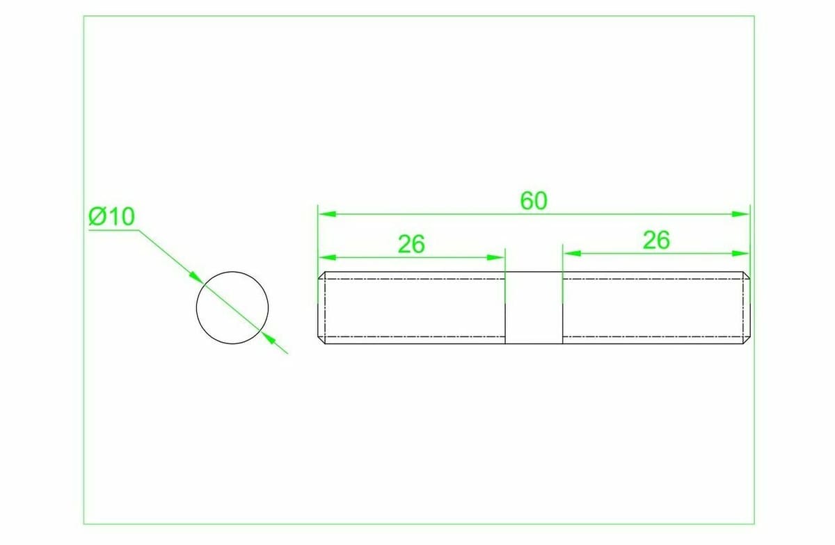
For this tutorial, we’re going to be making the valve pin shown in the image above. It may look simple, but it gives us the perfect opportunity to focus on the details of the program and the process.
A bit of background: A valve pin is a small metal piece that threads inside a tire valve stem. You may notice that, while we say it’s threaded, this isn’t shown in the picture. This is because, in the technical drawing norm, one should only show the length of the thread and of the internal and external radii, while the thread characteristics, such as pitch, should be indicated using the reference. For example, 2/TPI refers to the pitch and type of thread. This doesn’t affect the tutorial at all, it’s just a little nugget of information to take into account.
Importantly, all measurements are in millimeters. We won’t be going over how to add measurements to the diagram in this tutorial, but they’re presented in this image to help you along in the process of recreating the shapes.
What we will go over is how to create all the shapes appearing in the design, and then we’ll go over a bit of information on the file types.
Let’s get started!
Step 1: Setting Up
Before actually doing any drawing, we have to get our canvas ready, and this will be the case for any project you work on.
Note that you can exit an operation before performing it by pressing the Esc (escape) key on your keyboard.
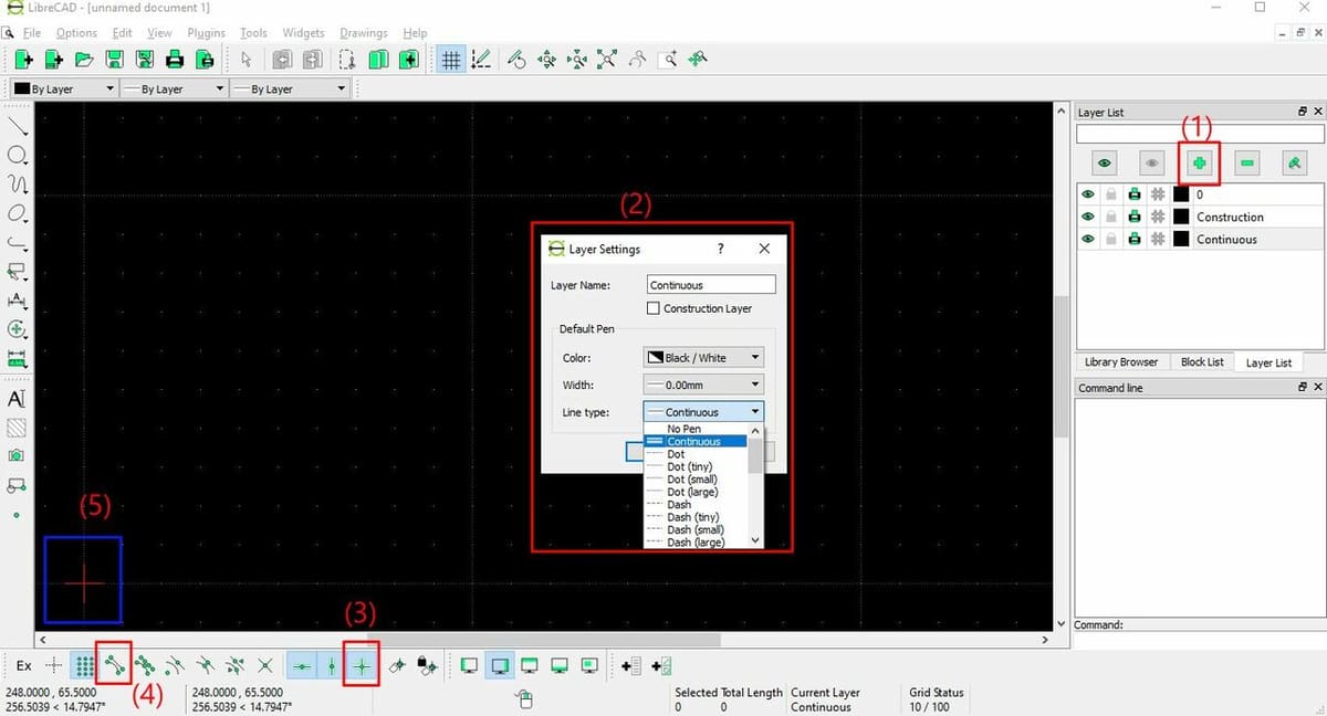
- Add two layers, one for a Continuous line and one for a Construction line. You do this on the Layer list by clicking on the ‘+’ button. A new window should pop open.
- In that window, assign a name, color, and line type:
- For color, we’ll stick with the default.
- For the Continuous layer, we’ll leave the default values.
- For the Construction layer, we’ll define the Line Type as “Dash-dot (small)”.
- In the Snap Selection toolbar, make sure that “Restrict Orthogonal” is selected. This will allow you to more effectively keep the lines horizontal and vertical. Otherwise, you’d have to check that each line is exactly horizontal or vertical.
- The Snap Selection toolbar should be displayed by default, but in case it isn’t, you can enable it on the top menu via “Widgets > Toolbars”.
- When you enable “Restrict Orthogonal”, “Restrict Horizontal” and “Restrict Vertical” will automatically become enabled as well.
- Notice the tools “Snap on Endpoints” and “Snap Middle”. These don’t need to be active right away, but take the time to locate and identify them, as we’ll be using them later.
- Finally, notice the red cross floating somewhere in the viewport, which indicates the origin point. Contrary to software like AutoCAD, in LibreCAD, this actually represents a significant origin point, therefore, our drawing will start from it.
Step 2: Drawing a line
We’re now going to create the side view of the pin, meaning the view where you can appreciate its length. However, we’ll first give a detailed explanation of how to create lines, and from there, the rest of the base shape will go quickly.
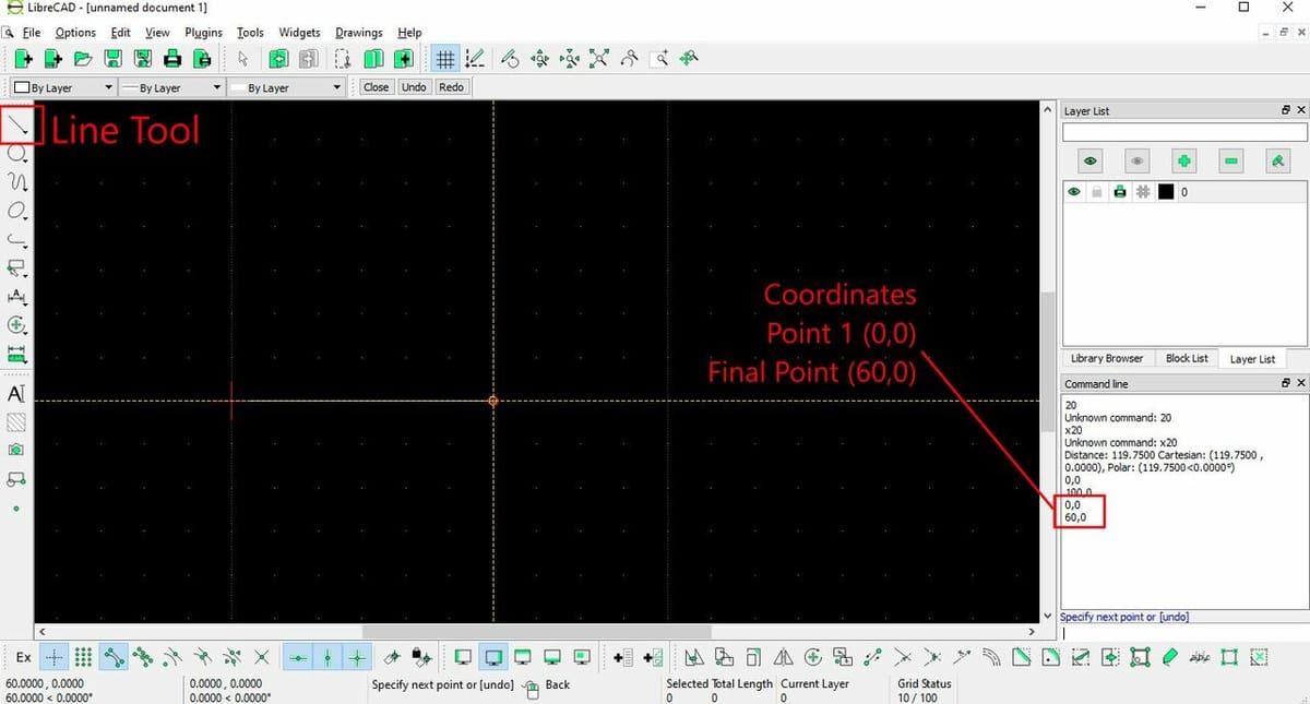
- To start, select the Line tool and choose a 2-point line.
- Force the line to start at the origin, meaning the “0,0” coordinates. There are two ways to do this:
- Option 1: In the Snap Selection toolbar, enable “Snap on Grid” and select the origin as your first point.
- Option 2: In the command line, type “0,0”. (If you type, the text by default goes to the command line.) This way, you’re indicating the coordinates of the first point of the line, with the notation “X,Y”. ‘X’ refers to a horizontal position and ‘Y’ to a vertical position. Notice that these are positions, not distances, made relative to the origin point, not to another previously drawn point.
- If you use this method, notice that the command line aids you with the message “Specify the first point”.
- Draw the 2-point line to the left, the positive ‘X’ side, with a final pin length of 60.
- Once again, you can use the “Snap on Grid” tool and the coordinates shown at the bottom of the screen to identify the X=60 point.
- In contrast, right after indicating the “0,0” coordinates for the first point, you can indicate “60,0” for the second point, and you’ll see your line drawn on-screen without moving your mouse.
Step 3: Creating the Base Shape
Now that we have an initial line, we can create the rest of the base.
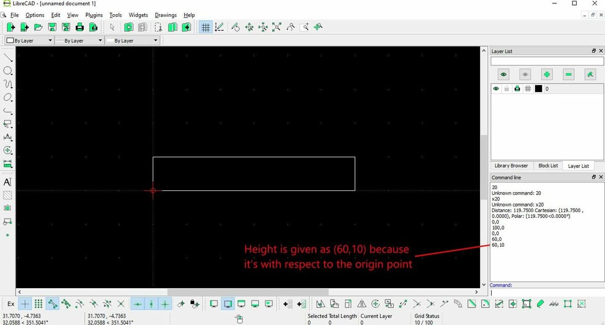
- Create a vertical line with a height of 10 mm. With “Snap on Endpoints” enabled, select the endpoint of the first line. Indicate coordinates of “60,10” on the command line to make it have a height of 10 mm.
- Draw a horizontal line originating from the previous one. Move the cursor to the left; it should stay horizontal because “Restrict Orthogonal” is active. Complete this line by hovering over the initial point (the origin), and because “Snap on Endpoints” is active, the program will recognize that you want an intersection and snap to the point where your rectangle line should end.
- Finally, draw a vertical line downwards to close the rectangle.
Step 4: Creating Offsets
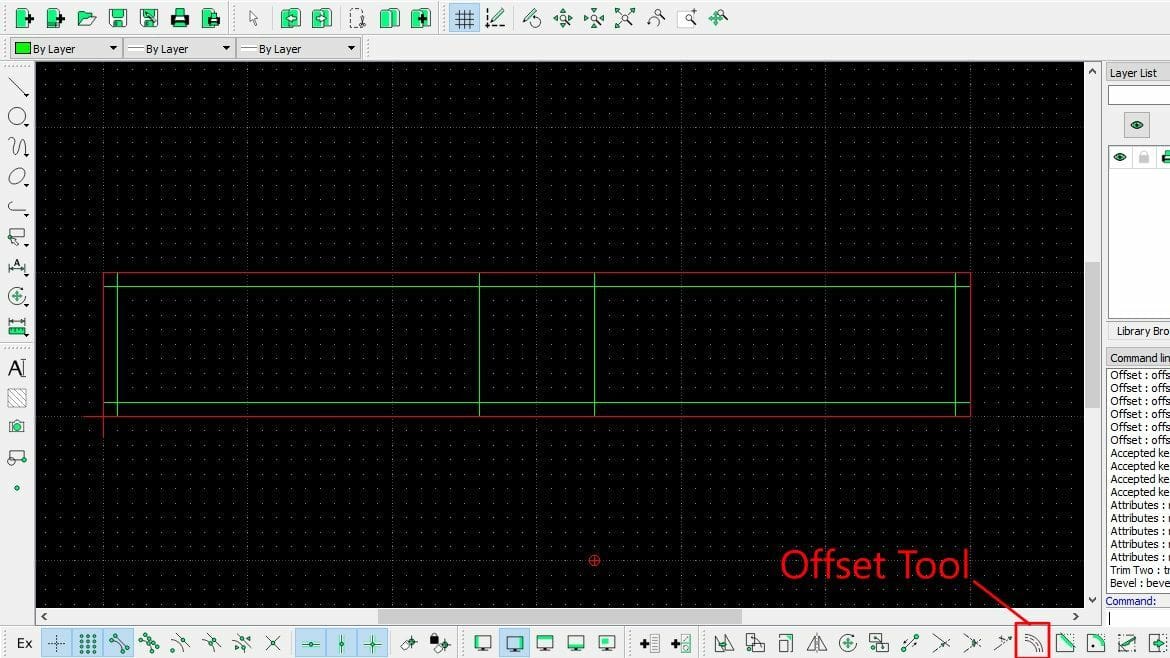
We have some extra lines to make, but these are parallel to existing lines, so instead of drawing them from scratch, we can offset them from existing lines. In the image, we’re showing the original lines in red and the final, desired lines in green. This is for clarity’s sake; you don’t need to change your line colors.
- Go to “Main Menu > Widgets > Toolbars”, and enable the “Modify” toolbar. This is where the Offset tool is found, which looks like a little curved road.
- Select the Offset tool. You have to do this line by line, for each final line.
- To create an offset, select the line you want to offset from, press Enter to indicate that you’ve finished selecting it, and then indicate the direction and distance of your selection.
Even if you make a mistake, you can select the line and drag it to the desired location. Tools like “Snap on Grid” and “Snap on Endpoints” are again useful here.
Step 5: Creating Fillets
We need to make the fillets seen at the corners of the rectangle.
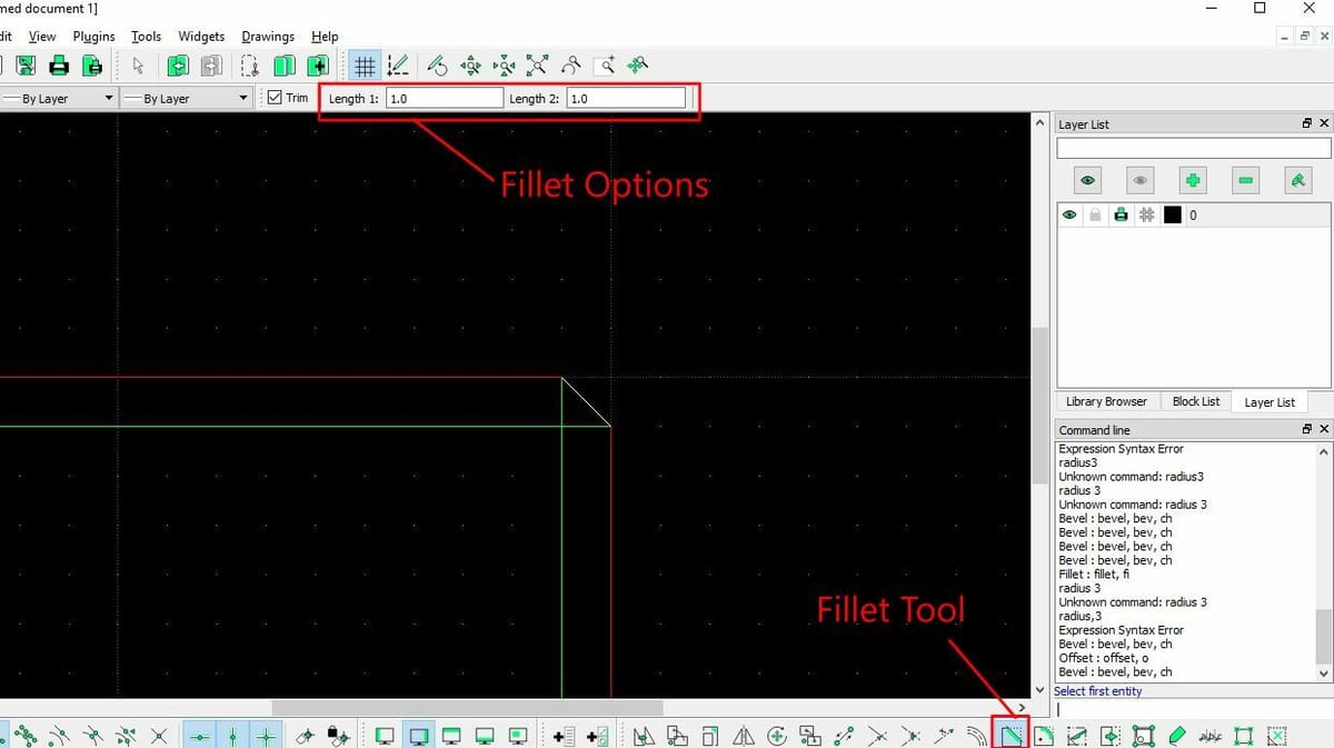
- Select the Fillet tool found in the Modify menu. It will ask you to select the two entities that will comprise your fillet.
- Pick the two intersecting lines. The image above shows the expected result of the first added fillet.
Note: Fillets have a radius of 1 mm by default. This works perfectly in this case, but in future projects, you may need different fillet radii. Thankfully, changing the radius is very easy. See the context menu in the top bar? There you can change the values according to what you need.
Step 6: Trimming
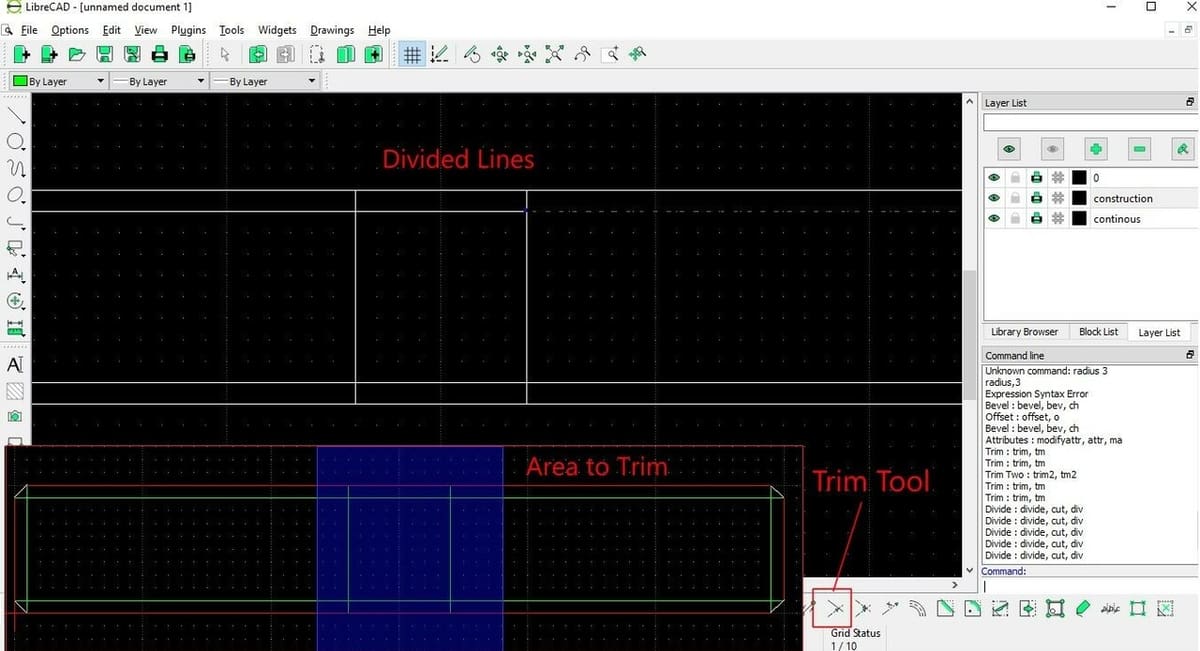
We now need to trim the lines highlighted in the image, as they’re not a part of the final desired drawing.
- Use the Divide tool, found in the Modify toolbar, to divide the lines in two, saving yourself some work in the long run.
- Select the horizontal line as your starting point and the vertical line in the middle right as your margin. You’ll notice that now you have two lines.
- Repeat this for the bottom line.
- Now use the “Trim” tool (not the “Trim Two” tool), to finish your trimming.
- You have to select two lines. The first one you select actually indicates your trimming limit.
- The second line indicates both what line you want to trim and what side of the line you want to keep, so be careful when selecting.
- The expected result can be seen in the next section’s image – you’ll notice that the inner horizontal lines in the highlighted area of the image above are now gone.
Now we have a good base for the model, but it’s time to make it fit some simple regulations.
Step 7: Using Construction Lines
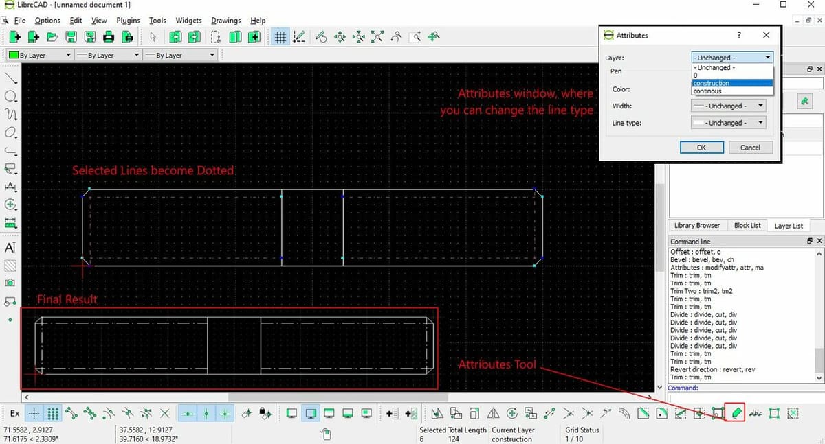
Since this is a threaded pin, the lines inside the pin indicate the internal diameter of the thread. This is, according to ANSI norms, how threaded elements should be shown. However, we’re missing a little detail: These parameters should be shown as construction lines.
We now have to convert these lines to the Construction layer. We could have done this from the start, but doing it this way allows us to see how to convert attributes in existing lines.
- Select the lines you want to convert. To select multiple lines, simply click on them consecutively; there’s no need to press any additional keys.
- Once selected, go to the “Attributes” tool in the Modify toolbar.
- Select the new layer – in this case, “Construction” – and select “OK”. You will see the change immediately: The lines should now be construction lines.
With this step, the side view is completed.
Step 8: Creating Circles
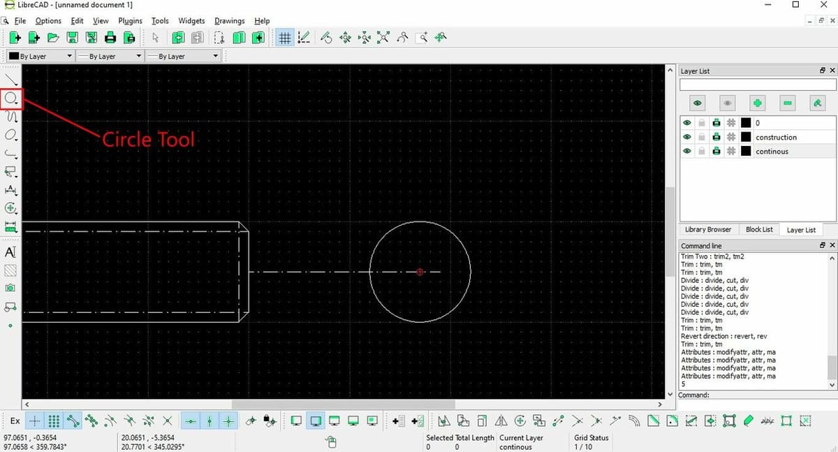
Now all that’s left to do is create the front view, which is simply a circle. The first thing to do is to indicate where the center of the circle will be located.
- Staying in the Construction layer, enable “Snap Middle” in the Snap Selection toolbar.
- Create a line from the center of the right border of the side view to some distance out of the shape.
- The endpoint of this line indicates where our circle’s center will be located.
Finally, we create the circle.
- Go back to the Continuous layer. To do this, simply click on its name in the Layer List.
- Select the Circle tool. There are many circle types, but the most used and the one we need in this case is “Center Point”. This circle requires two parameters: The location of the center and an outside point, or the location of the center and a radius.
- Select the end of the line as the location of the center.
- Notice how now the command line is asking for the radius and input ‘5’. We know the value to be 5 mm because the diameter is 10 mm.
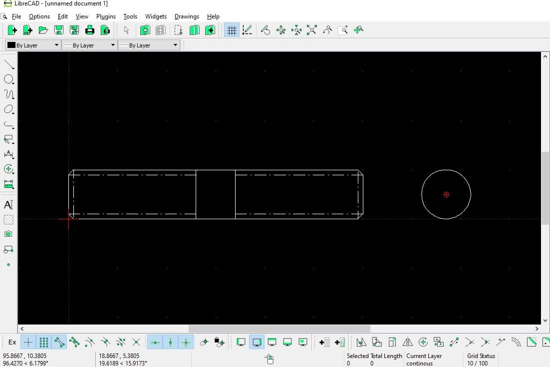
- Select the line and delete it by pressing the Delete key, as we only needed this line for guidance.
You can zoom out and see the finished result!
File Formats
We’ve successfully finished creating a LibreCAD drawing! It’s now time to save it, so here’s some useful information about file formats in LibreCAD.
Save As
When saving a file using “Save As” in LibreCAD, the default is to save the file using the DXF format. This is a very common file for CNC and most CAM programs read it. Other 2D CAD software like AutoCAD or DraftSight can read DXF as well with no issue, so it’s overall a good format to work with. DXF is more universal than DWG because AutoCAD holds the copyright for DWG and only the 2010 version is compatible across all platforms. New versions are “version sensitive”. DXF, in contrast, is compatible across any program that can read it, regardless of version.
You can also see that in the “Save As” option, in File Type, there are no other file options available, such as DWG. So saving as DXF is your only option.
Export
Using the “Export” option, you can opt for PDF, to be used, for example, as blueprints. Another option is exporting as SVG, which is a vector file format also accepted in many CAM programs as well as in 2D design software like Inkspace. Finally, there’s also the possibility of exporting as an image, in which case you can choose from a large pool of raster files, such as PNG or JPEG. This is mostly useful for sharing and visualization purposes, as all utility and ability to edit would be gone.
License: The text of "LibreCAD Tutorial for Beginners: 8 Easy Steps" by All3DP is licensed under a Creative Commons Attribution 4.0 International License.