Inkscape Laser Engraving Plug-in: Tutorial for Beginners

Follow this tutorial for the Inkscape laser plug-in to take your laser cutting designs from drawing to G-code all in one program!
Computer-aided manufacturing (CAM) software is a key part of the process to create or embellish an object with a CNC machine. The CNC process typically consists of creating a design, setting up that design to be cut, and cutting it. That second step is what CAM is all about.
CAM is the process of setting up your tool and toolpath to generate G-code that your machine can interpret and use to cut, mill, or engrave the desired shape. In the CAM process, you need to define the dimensions of your cutting surface, establish the tool your machine will use during the cutting process, and finally, set the toolpath your machine will follow as it cuts. This includes setting up factors like speed, depth, and number of passes, among others.
Typically, to make a piece using a CNC machine (e.g. a laser cutter or engraver), you first have to create your design in CAD software – for example, AutoCAD or Inventor. Once that’s done, you export it to software that specializes in (or at least supports) CAM, like Autodesk Fusion. However, in vector-drawing programs like Inkscape, you get the option to prepare the CAM process directly in your drawing software.
In this article, we’ll take you through the process of preparing a drawing for laser cutting or engraving using the Inkscape laser plug-in, which means your file can be prepared for machining all in one program!

What Is Inkscape?
Inkscape is free drawing software that’s available for Linux, Windows, and MacOS. Inkscape can import and export raster files such as PNG and JPEG, but its primary purpose is for creating and editing vector graphics. It’s a popular tool among CNC machine users, not just because it’s free, but also because vector graphics are the preferable method of working when creating 2D designs.
Another advantage is that Inkscape is open source, allowing third parties to develop, use, and distribute plug-ins that expand the functionality of the program. Such is the case of the Inkscape Laser Tool Plug-in, which allows you to prepare the CAM process for laser cutting and create the necessary G-code directly in Inkscape, eliminating the need to export your drawing and import it into different software.
Installing the Plug-In
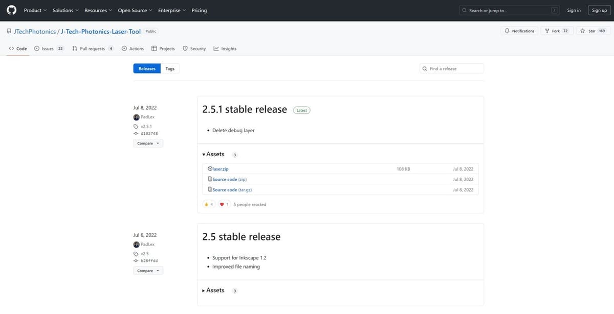
The plug-in was developed by J Tech Photonics, and it’s available for download from their website, although the latest updates will usually be found on GitHub. It’s important to note that to upgrade to a newer version, you must uninstall any older versions before installing the newest. You also have to take into account the version of Inkscape, as you have to select the correct version of the plug-in to install.
YouTuber inquisitiveYT made a pretty robust YouTube tutorial for the J Tech installation process on an older version of Inkscape. While the user interface is different in the tutorial, the file locations and general process is the same.
Before installing the plug-in, make sure Inkscape is closed. The process is fairly straightforward.
- Download the ZIP file of the correct version.
- Extract the contents and save them to Inkscape’s installation folder by following the path from the Inkscape program file “Inkscape > share > inkscape > extensions”.
- For Windows machines, this will typically be “C:Users\<yourUsername>\App\DataRoaming\inkscape\extensions”.
- You might have to unhide hidden folders to access the AppData folder from the file manager.
- Once you’ve pasted the plug-in files in the correct folder, the next time you open Inkscape, the plug-in will appear in the “Extensions” tab on the menu bar.
Tutorial
The process of creating a toolpath is pretty much the same regardless of the design you’re working with, no matter what you want to cut and engrave. An important detail to keep in mind is that the plug-in only works with SVG files, so if the design you want to cut wasn’t created in Inkscape, you’ll need to convert it to this format first.
In the sections below, we’ll take you through how to verify your drawing will be correctly cut, then how to convert it from a drawing to a path that can be followed. We’ll also look at how to use the plug-in and the optimal settings for laser-cutting success.
Step #1: Setting Your Stock
Before getting into the CAM process, it’s important to make sure the drawing is made in such a way that you’ll get the desired result. For this reason, let’s start by checking out the basic CAM settings.
When using the plug-in, the program interprets the bottom left of the drawing space as the 0,0 coordinates of your machine, so you need to be careful of where on the page your drawing is located. We recommend doing the following:
- After creating or importing your drawing, add a surrounding rectangle with the dimensions of your slab of wood (or other material to be cut) so that you can locate where on the surface you want the drawing to go.
- Go to “Edit > Resize Page to Selection” to reduce the size of the drawing space to the size of your slab of wood.
- Delete the rectangle that you just drew, and you’re ready to go!
Step #2: Importing Images
It’s also possible to import a raster image rather than designing an illustration from scratch. You just have to take into account that it should have good contrast and quality so that it can be properly interpreted by the software.
- Import an Image by going to “File > Import” (or by clicking “Ctrl + I”), and then selecting the image or vector file using your computer’s file manager.
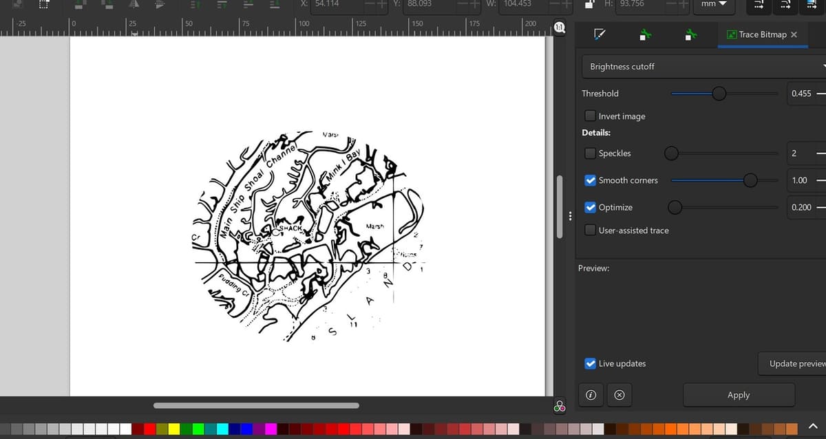
- To convert a raster image into a vector object that can be cut, go to “Path > Trace Bitmap…” in the top menu. This will convert your image to a solid vector object.
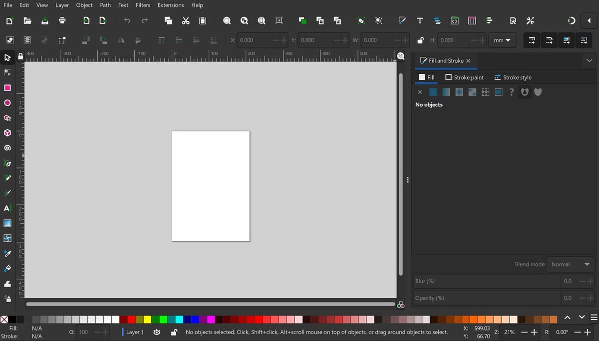
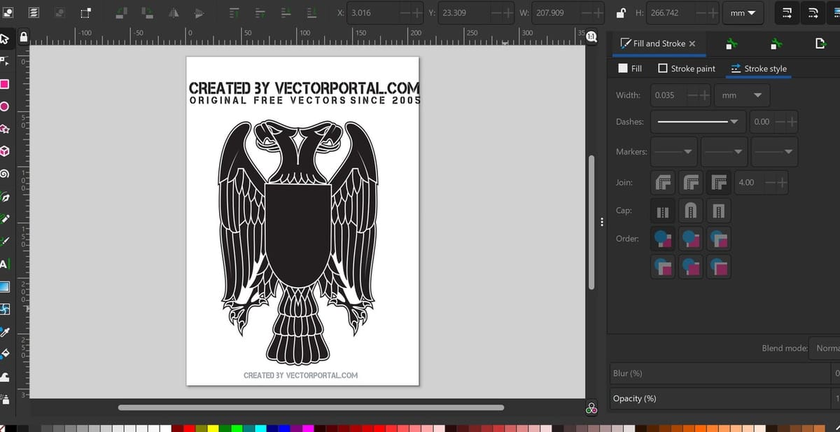
- To verify that your image doesn’t have additional lines and that Inkscape is selecting the correct lines to cut, you can check the outlines. To do this, go to “Fill and Stroke”, which you open with the hotkey “Shift + Ctrl + F”.
- Select a null Fill and a solid Stroke paint. This will show you what the software considers to be the outer lines of your shape.
Solid color in a shape means the laser will engrave the whole area, while having only the outline and no infill will obtain an outline when laser cutting. This is because when you cut through the exterior, those sections would just fall off!
Step #3: Creating a Path
Creating a path means the object will stop being represented as only a drawing. It will now have mathematical properties, like direction and size, that can be interpreted by CAM software. Depending on the number of objects in your scene, you may have to do an additional step before you create the path.
If you have multiple objects you want to cut using the same setup, you have to group the objects first. This will make them behave the same, and the CAM process will be done with the same settings for all objects. This is important because grouping them will also create a path from one object to the other – in other words, coordinates of translation between objects.
- If you have multiple objects you want to cut using the same setup, once they’re drawn, go to “Object > Group” (or click “Ctrl + G”) in the menu.
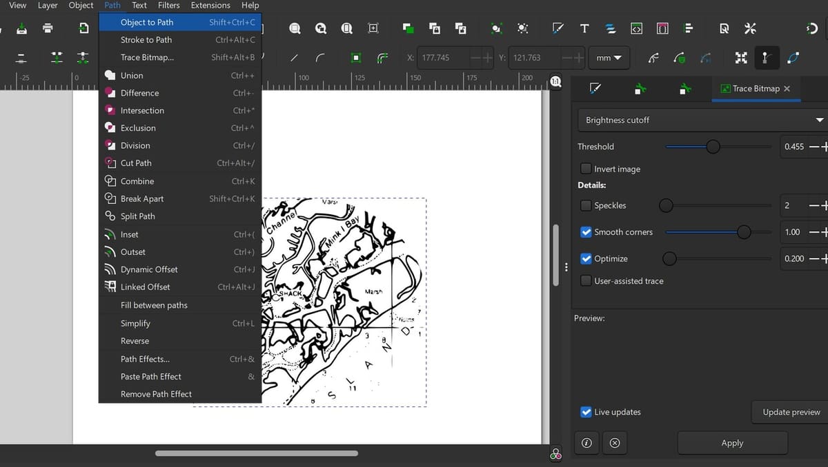
- Once the objects are grouped, or if you only have one object, simply select the object and go to “Path > Object to Path” (or click “Shift + Ctrl + C”) to create a toolpath. This will create one cutting path for the object or group of objects.
Step #4: Opening the Plug-In
Now that the program can interpret the drawing as a set of coordinates, it’s time to use the plug-in to convert this information into the G-code your laser cutter will follow.
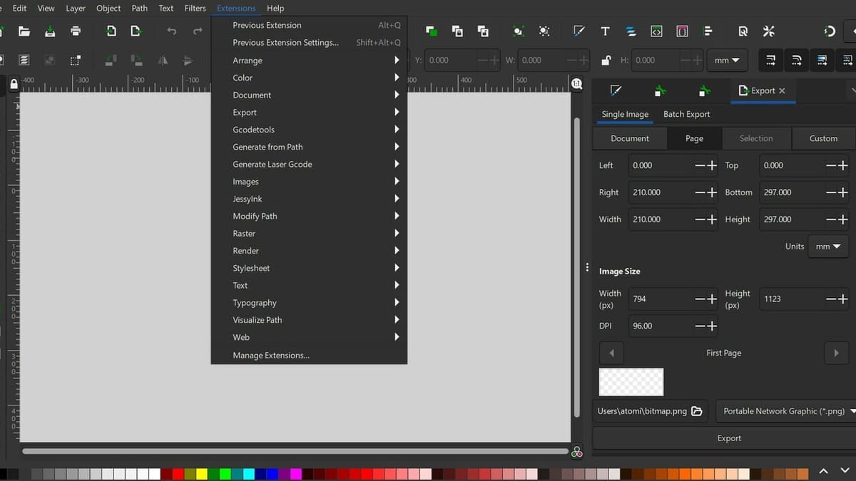
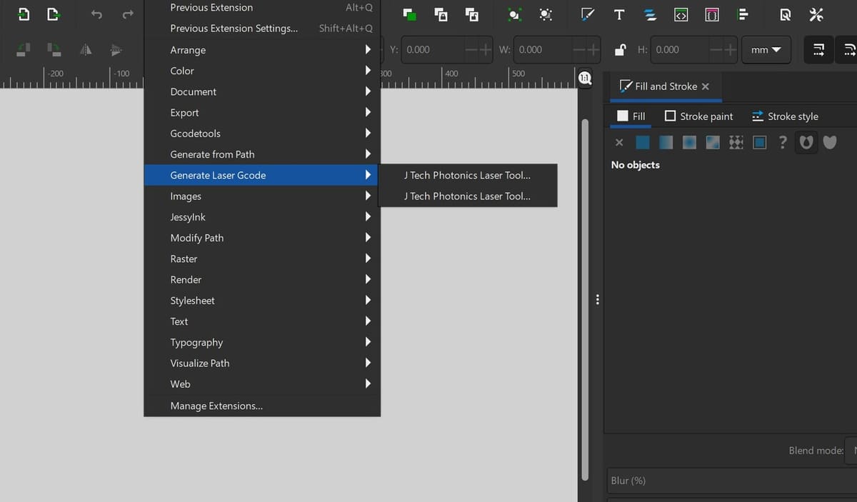
- On the menu, under “Extensions”, go to “Generate Laser Gcode”. It will show you that the J Tech plug-in has been added.
- Once selected, a dialog box will open where you can set up your laser cutter.
Aspects like laser power or laser speed will depend on your machine and on the type of cut you want – for example, if you want to engrave or cut through. These are things you should already know from previous experience with your machine, but if you don’t, start by running some tests to try different intensities and speeds to learn how your laser works.
Step #5: Plug-In Settings
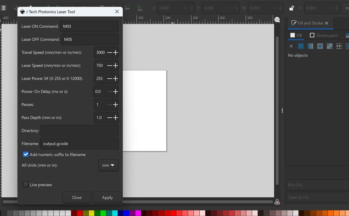
Here are some recommendations to take into account while setting up the laser cutter:
- It’s important to remember that a laser cuts right down the middle of the indicated path, in contrast to, for example, a mill, which would cut from a side.
- If you want to engrave rather than cut through, take care to use a lower intensity and a smaller number of passes.
- You can customize the Laser On and Off G-code commands, in case your firmware uses different commands from the ones indicated by default.
- The maximum laser power depends on the capacity of your laser.
Then, the final step is to indicate the filepath of the folder where your G-code will be stored. You can’t browse for it, so you have to go into your explorer and copy the folder’s address. Make sure the live preview is selected, then click on Apply. You’ll be able to see a preview in Inkscape of the toolpath your machine will follow.
Starting the Laser Cut
Once the file is completely prepared in Inkscape, it’s important to make sure that the laser toolhead is positioned correctly over the object being cut.
Different brands of laser cutters have different control types, but a general overview of how to do this is as follows:
- Move the laser head to the bottom-left corner of the part of the material that you will be cutting. This will be the point that the laser cutter interprets as the bottom-left corner of the laser job being sent to it.
- Check that there is enough stock to complete the cut by moving the laser to the four corners of the job and verifying that the laser never travels over a hole in the stock or goes past the end of the stock.
- Return the laser cutter to the bottom left-hand corner of the job. Adjust the stock or the position of the laser as necessary to ensure that the laser will cut on the correct part of the stock.
License: The text of "Inkscape Laser Engraving Plug-in: Tutorial for Beginners" by All3DP is licensed under a Creative Commons Attribution 4.0 International License.