Inductive Sensor (3D Printer): All You Need to Know

On a printer like the Ender 3, inductive sensors are used for auto bed leveling. Read on to learn all about inductive sensors on 3D printers!
Glass Doesn't Pass
In 3D printing, automatic bed leveling (ABL) has become more common with the development of affordable, accurate sensors, like the BLTouch.
The process is performed using a sensor that measures the distance between points on the bed and the probe. Once measured, the printer creates a digital mesh out of the distances from the nozzle to different points on the print bed. Then, the firmware can be assured that the nozzle is consistently the same height over the bed.
Endstops, also known as limit switches, are the devices used in 3D printing to tell the printer that a carriage or gantry has reached the end of its axis path. Bed leveling sensors are essentially just a special type of endstop, as they perform the same role. However, bed leveling sensors are typically more accurate and precise than regular axis limit switches. There are a few types of endstops including mechanical and magnetic (also called Hall effect sensors).
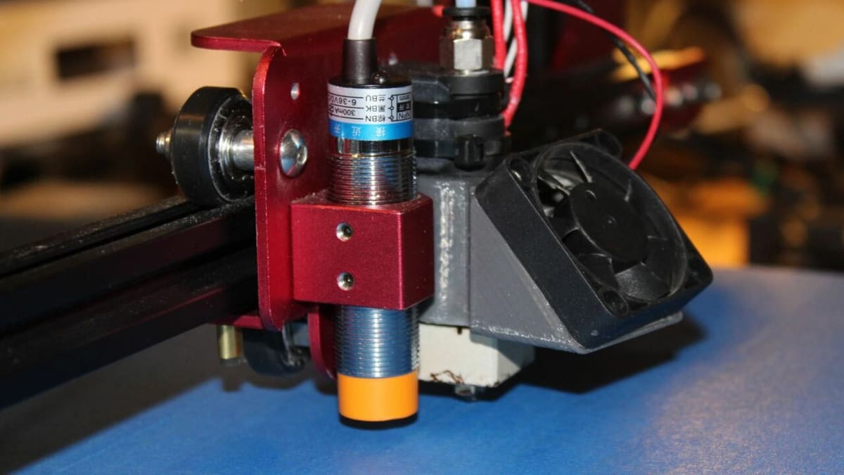
Inductive sensors are another type of endstop, most similar to a magnetic endstop, but with a twist. Instead of detecting a static magnetic field (like a magnet), inductive sensors produce a magnetic field and detect changes in the field from interfering metals. When inductive sensors measure a certain amount of interference from metals in their magnetic field, they’re triggered.
In this article, we’ll go over how inductive sensors work and how they’re used on 3D printers. We’ll also compare them to other sensors, give a brief overview of the basic installation steps, and provide a few brands of this type of sensor. Let’s get started!
How They Work
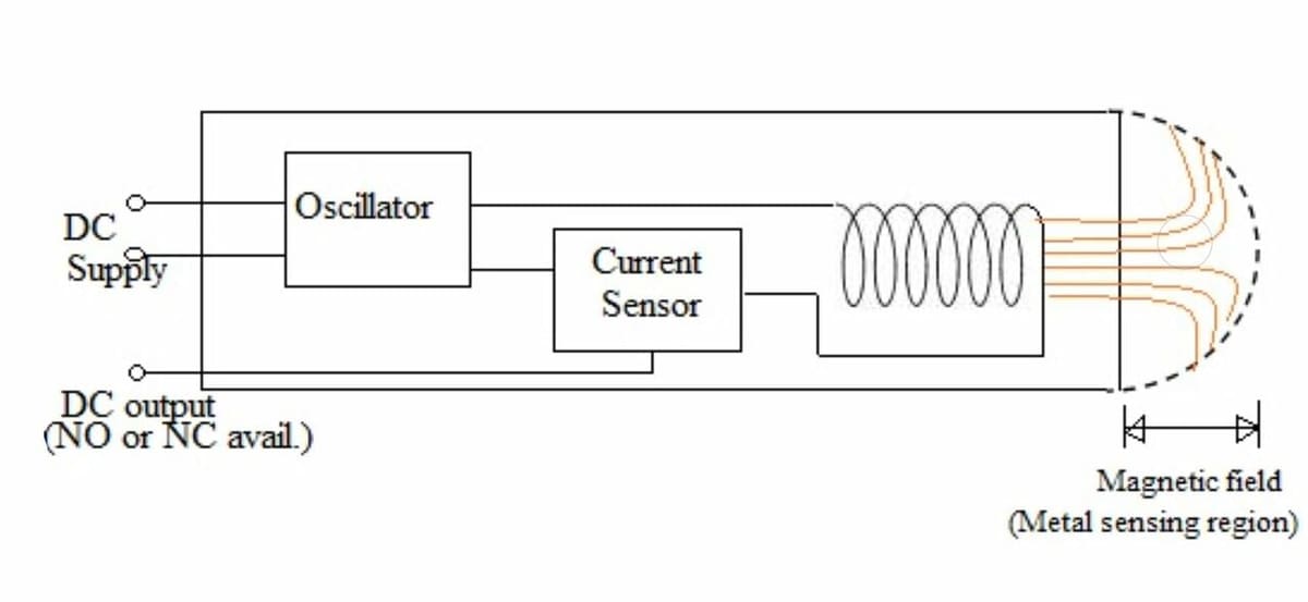
Inductive sensors, as we mentioned, work by producing a magnetic field and detecting the field’s interference. This type of sensor works by proximity and is non-contact, so metals can be detected from a small distance or gap.
Inductive sensors produce a magnetic field with an induction coil that has current flowing through it from the attached positive (charged) wire. Due to the circular coil, inductive sensors almost always have a cylindrical shape.
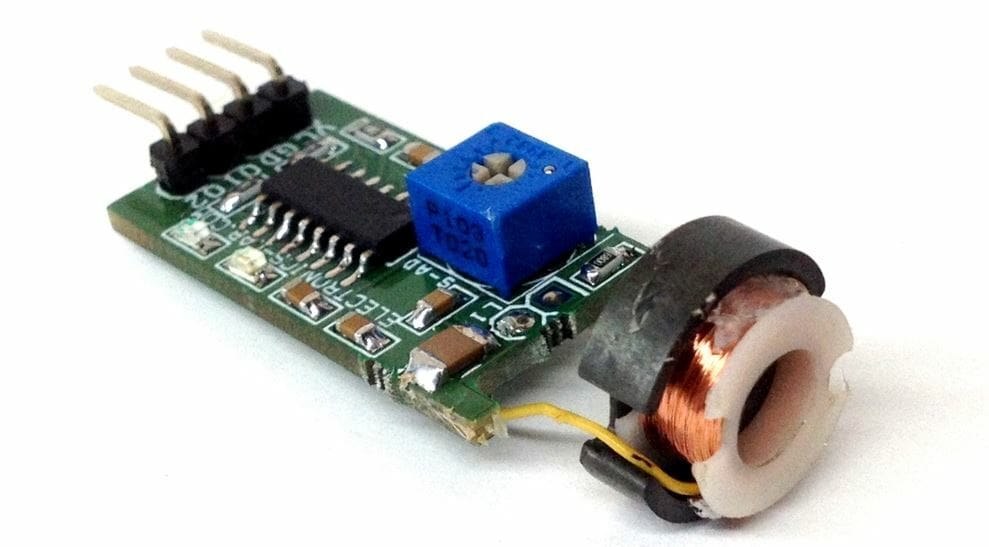
The positive power wire goes in and attaches to the coil and provides a current to produce the magnetic field. At the same time, the ground wire is connected to the other end of the coil and an electrical current sensor, which detects the current interference.
Only metals produce enough interference to the induction coil’s magnetic field to be picked up by the current sensor device. This means that the sensor should maintain most of its accuracy even when wet or dirty as long as nothing disrupts the sensor or any nearby metals. On this note, non-metal objects can prevent inductive sensors from detecting a metal if they are in between the sensor and the metal.
Sensitivity
As you can expect with most sensors, different inductive sensors have different sensitivities or detecting distances. The detecting distance is determined by the ferromagnetic core in the device and its strength.
Inductive sensors, when sold, usually have a specified approximate range for detecting distance, measured in millimeters. For example, an M12 4-mm sensor has a 12-mm diameter head with a 4-mm detecting distance, and an M18 8-mm sensor has an 18-mm diameter head with an 8-mm detecting distance. You can check out Thomas Sanladerer’s sensor testing video to learn more about accuracy for inductive sensors.
Now, let’s get into the uses!
Uses
In 3D printing, inductive sensors really only have one main use: automatic bed leveling. With an ABL sensor, you don’t have to go through the hassle of manually leveling the bed.
While other types of endstops, like mechanical or magnetic ones, can serve as endstops for the X-, Y-, and Z-axes, inductive sensors cannot. That’s because they’re too sensitive to all metals, so unless your printer’s frame contains no metal pieces, you can’t use an inductive sensor as a generic 3D printer endstop.
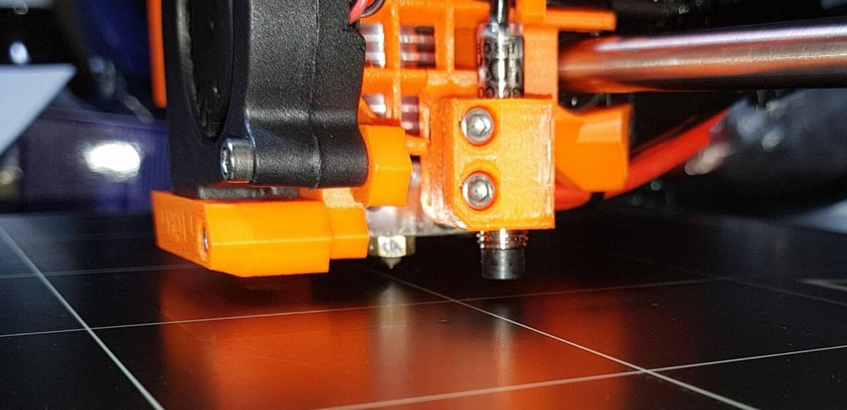
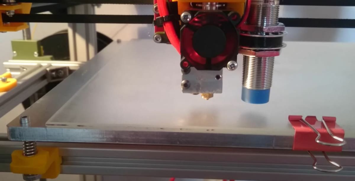
Inductive sensors can be used as an ABL sensor, but only with a metal build surface, like the Prusa MK3S+‘s spring steel bed. However, many printers (like the Ender 3) have an aluminum bed underframe, which the inductive sensor can detect if the non-metal surface isn’t too thick. So, if you want to use a non-metal build plate (such as glass, polypropylene, or another surface), know that it might not work.
If you want the best chance of success, you can get a sensor with a detection distance that exceeds the thickness of the non-metal surface. You can also try to get a thin non-metal surface. Some users have found that inductive sensors do work on normal (thickness-wise) glass, though. So, you may be lucky enough for it to work without an especially sensitive inductive device or thin build plate.
Comparison
All in all, inductive sensors are a great option, but how do they compare to other types of endstops, like a mechanical limit switch? According to Thomas Sanladerer’s thorough testing process, inductive sensors are more precise and consistent, with a lower standard deviation. He also found that inductive sensors are more reliable than their mechanical and optical counterparts.
Mechanical endstops are cheaper ($1-$2) than inductive sensors (~$10). So, if budget is the main concern, a make-shift mechanical sensor may be the cheapest option. Also, mechanical endstops usually have a rectangular shape with mounting screws, while inductive sensors are typically in a cylindrical casing. The shape of a typical inductive sensor may make it slightly more difficult to mount but still not very hard.
Options & Installation
If you’re looking for an inductive sensor, there are many different options. Below are three great choices:
- TH3D Ezabel Pro
- Size: 18 mm
- Detecting distance: N/A (works with glass and any printing surface according to TH3D)
- Price: ~$65
- PINDA V2
- Size: 8 mm
- Detecting distance: 2 mm
- Price: ~$20
- Twidec M12 4-mm
- Size: 12 mm
- Detecting distance: 4 mm
- Price: ~$15
How to Install
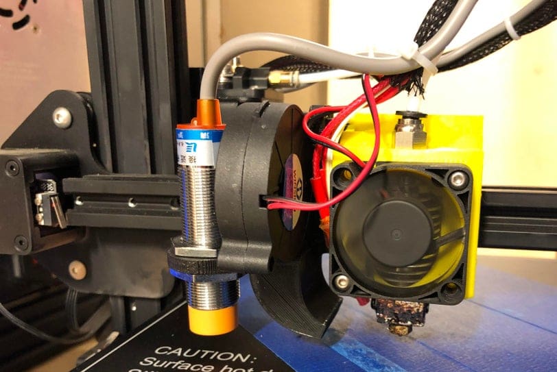
If you want to install an inductive sensor, it’s not hard at all. We’ll use the Ender 3 and the TH3D Ezabl sensor as an example. The main steps, however, are very similar to the process on other 3D printers.
- Print a compatible mount for the Ender 3 and your (Ezabl) inductive sensor.
- Download TH3D’s Unified 2 firmware for the Ender 3 or build your own firmware that supports your (Ezabl) sensor.
- Flash the new firmware onto your printer’s mainboard and LCD if applicable.
- Save the firmware on the LCD or send the M500 command (saves the changes) on a G-code terminal hooked up to your printer’s mainboard.
That’s it!
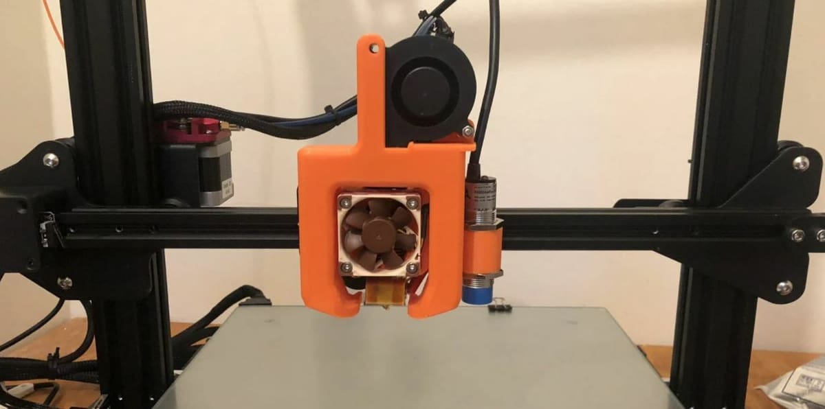
Lead image source: Crucible3d via Reddit
License: The text of "Inductive Sensor (3D Printer): All You Need to Know" by All3DP is licensed under a Creative Commons Attribution 4.0 International License.
CERTAIN CONTENT THAT APPEARS ON THIS SITE COMES FROM AMAZON. THIS CONTENT IS PROVIDED ‘AS IS’ AND IS SUBJECT TO CHANGE OR REMOVAL AT ANY TIME.