Hall Effect Sensor & Arduino: How to Make Them Work

With a Hall sensor, Arduino projects can detect magnetic fields. Learn how to expand your project's capabilities with Hall effect sensors!
In the ever-diverse world of engineering, there’s one theme that remains consistent: Using science, math, and technology to solve real-world challenges around us. This theme unites all areas of engineering to one common cause. Many times, the solution to these challenges is the creation of new technologies and processes.
Melding several engineering disciplines together, the field of mechatronics sets to blur the lines of what’s possible. If you want to make your project come to life, sensors are a key component. They’re an easy and fantastic way to add capabilities to your project.
Being plentiful and easy to obtain, Hall effect sensors can add great new functionality at a very economical price. In this article, we’ll do a deep dive on sensors – especially the Hall effect sensor, and we’ll explain how to integrate them with an Arduino board.
Join the Dark Side

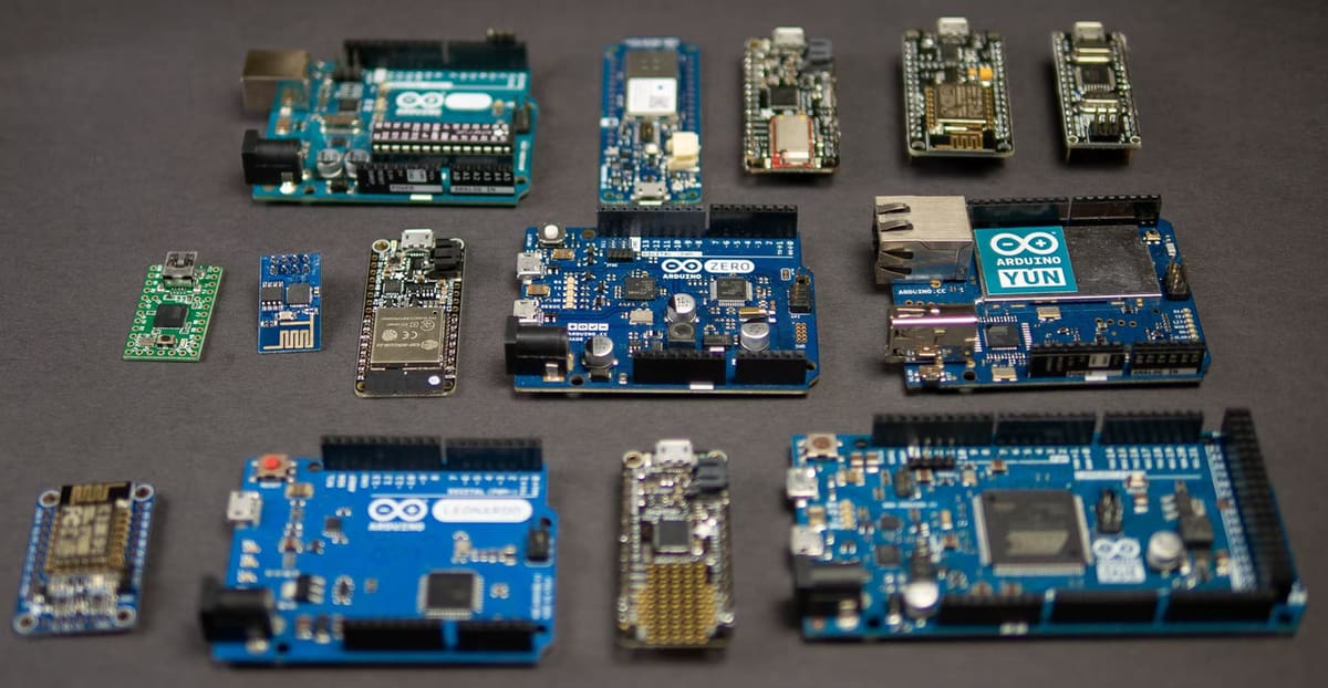
Whether you’re a hobbyist or a professional engineer, working with microcontrollers is nearly essential. And for that reason, Arduino has been the go-to for electronic projects for years. Linking the two worlds of mechanical and electrical, Arduino uses sensors to see the world around us. In effect, Arduino boards can create truly “smart” devices that interact with their environment.
Sensors come in many different forms, but all fall into two main categories:
- Contact sensors: This type of sensor relies on physical contact to work, which is particularly well suited for stationary measurements. Examples include direct contact temperature sensors and potentiometers. However, things that move, especially repetitive movements, will wear out contact-type sensors in a hurry.
- Non-contact sensors: These are exactly what the name implies. These sensors rely on taking measurements without direct contact. Infrared temperature guns and light sensors are great examples. Since there’s nothing to wear out, these sensors often outlive what they measure. The trade-off, though, is their complexity and price.
We know that sensors give Arduino boards the ability to see the world. Either contact-type or not, there are sensors to measure nearly everything. But what about sensing things that can’t be seen, felt, or heard?
Magnetic Fields
Fiction aside, what we’re talking about here are magnetic fields, which surround us every day without us even knowing it. But what exactly are magnetic fields? Strangely enough, nobody knows exactly what a magnetic field is. What we do know is how to create and use them.
The study of magnetism and magnetic fields gets so involved that we can’t possibly cover everything. It’s important to cover the two main forms, though: permanent magnets and magnetic induction.
- Permanent magnets: They both (should I say…) emit magnetic fields. The real difference is that a permanent magnet is magnetic by nature. Like a magnet stuck to a fridge, it’s magnetic and likes to be that way.
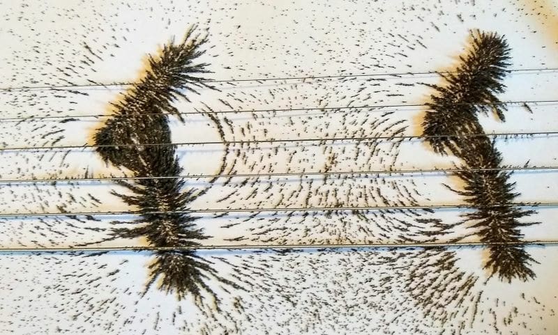
- Magnetic induction: Magnetic induction is a little different. Any time electricity flows in a wire or conductor, a small magnetic field is made around that conductor.
We can make this small magnetic field bigger by wrapping the conductor around something that’s iron-based. Remember the old science fair wire-around-the-nail exhibit? Same thing happening here. Once we take the power away from the circuit, our nail stops being a magnet.
Detecting Magnetic Fields

Whether we’re working with permanent magnets or magnetic induction, a magnetic field can be detected in several ways:
- Reed switch: This tried-and-true switch has a small metal tab inside that reacts to a magnetic field. When the field gets big enough, the metal tab moves and the switch changes state. This is the same technology found in budget proximity switches. It’s economical and reliable, but slow.
- Inductive sensor: This sensor works by measuring changes in the magnetic field at the business end of the sensor. These work well as signal generators, but they can only detect changes in a magnetic field. They don’t detect the presence of one.
- Hall effect sensor: This amazing little device can detect the presence of a magnetic field. It does this by sensing current flow through an internal conductor. When a magnetic field comes close to the sensor, the current flow through the internal conductor changes. This is called the Hall effect.
The Hall Effect Sensor
Since their introduction, Hall effect sensors have been a staple in automation and robotics. There are many different versions, sizes, shapes, and voltage ratings. Many are packaged with additional circuitry to provide a convenient square-wave output. Coupled with lightning-fast response times, these sensors provide an ideal way to sense movement through magnetic fields.
Hall effect sensors are used in many other industries besides automation and robotics. They’re found in the manufacturing field as speed and positioning sensors on assembly lines and machines. They’re critical in the automotive field for engine timing and vehicle speeds. Anti-lock braking uses them for sensing wheel lock-up, for example.
Interface Options for Your Hall Effect Sensor
It’s easier than ever to hook up a Hall effect to a microcontroller. There are nearly limitless options for interfacing the sensor, too. Depending on your project and the type of control system involved, you can hook the sensor up in several different ways. Let’s take a look at a few.
- Analog: Connect the sensor output to a transistor or op-amp circuit to directly control an output. Most sensors can source enough current to trigger LEDs directly.
- Digital: Connect the Hall sensor to other digital circuitry such as counter or gate chips.
- Programmable circuitry: Connected to a microcontroller for programmable control.
For overall ease and simplicity, a Hall effect sensor works very well when connected to a microcontroller. In this way, wiring is simplified, and the overall component count is kept low. Arduino boards and the Pi Pico can be used and also single board computers such as the Raspberry Pi.
Arduino boards are a good choice because they’re plentiful, cheap, and extremely well backed. They’re also fairly robust and can take a fair share of “oops” abuse without letting out the magic smoke.
There are many great boards you can use with a Hall effect sensor. Because all you need is one input pin, any board can work well. For this next example, we will be using an Arduino Uno R3.
Making It Go!
This example is to show the basic circuit hook up and programming. You’ll need to reference the datasheet for your sensor and follow the appropriate safety guidelines for working with electronics. This example isn’t a complete walk-through, as there are too many variables that could change.
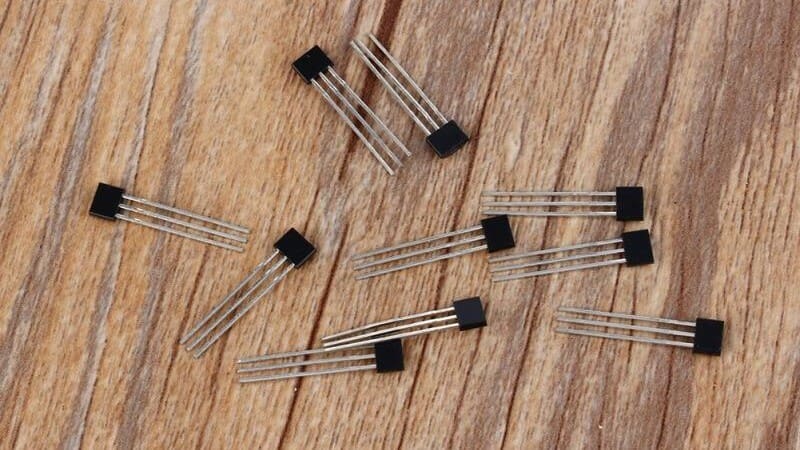
We’re going to use the A3144 Hall sensor for this example. This sensor is +5 V compatible and features a square wave output that switches high when a magnet is sensed.
The A3144 sensor is very simple to use and only has three pins. Looking at the front of the sensor (the side with numbers), the pins are numbered 1-3 from left to right:
- +5-V power (+5 V)
- Ground (GND)
- Output (GND when a magnet is sensed, otherwise +5 V)
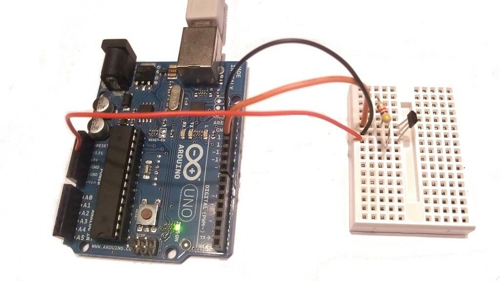
Step by Step
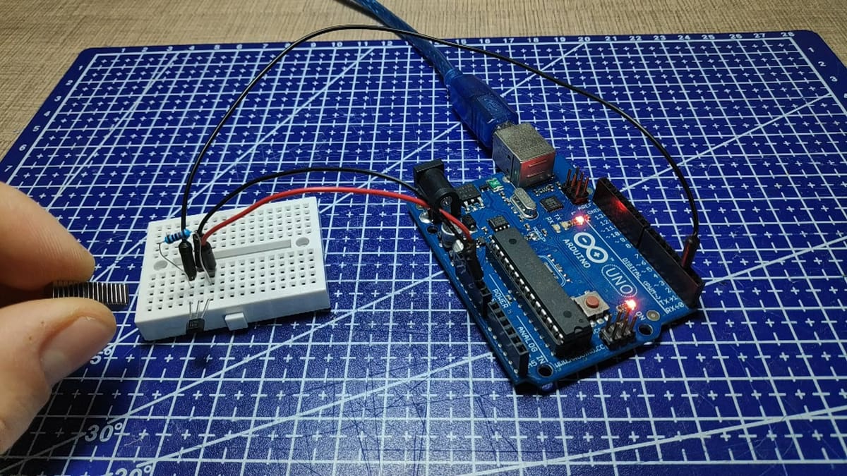
You can interface the sensor with the Arduino as follows:
- Hook the sensor’s +5-V and GND pins to your Arduino using the onboard +5 V and GND.
- Hook the sensor’s output pin directly to the board (pin 13 is the Arduino’s LED if you want to use that).
- Add a pull-up resistor from the output pin to the Arduino’s +5-V pin.
When the Hall effect sensor switches on, the sensor connects GND to the Arduino’s input pin. When the Hall effect sensor switches off, the connection to GND is removed. This still leaves zero (or low/no/null) voltage at the Arduino, and it’ll still think the sensor is on. The resistor “refills” the power that was taken by the sensor, and the Arduino sees +5 V at the pin again with the Hall effect sensor switched off.
After hooking everything up, programming the Arduino is very simple. The Arduino can read the sensor by using the digitalRead() function as well as other functions such as interrupts. An easy example for coding can be found right in the Arduino IDE. Navigate to “File > Examples > 02.Digital > Button”.
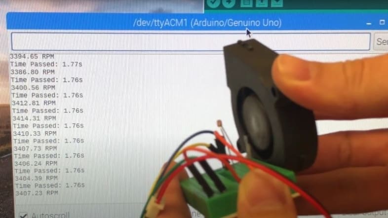
What you choose to do with the rest is only limited by your imagination! Here are some cool projects using the A3144 sensor:
- A fan tachometer to measure fan speed
- A smart railway crossing for a toy train
Pros & Cons
With every project, there are always things to consider. No matter how big or small, it’s important to weigh your options when adding new components. Luckily, there are only minor cons when adding a Hall effect sensor (this is one reason why they’re so popular!).
Pros
- Hall effect sensors can add new capabilities to your projects.
- Your project will be able to detect magnetic fields.
- They’re easy to integrate with other forms of technology. For example, some smartphones and tablets use them to detect when accessories are attached.
- They’re cheap and easy to obtain.
Cons
- Adding a Hall effect sensor adds additional circuitry and programming complexity.
- They could reduce the available pins on your microcontrollers.
- Other options may be easier to implement.
- Hall effect sensors suffer from drift over time. While not being a big deal for simple projects, high precision projects may need higher quality sensors.
- They can be falsely triggered under certain circumstances.
Integrating Your Hall Sensor
So you’ve decided to use a Hall effect sensor in your project. That’s great news! But where do you start? There are a few simple things to check to get you on the right track.
- What will you be sensing? You can use a Hall effect sensor to sense any magnetic field. This can be a magnet on a moving arm, a rotating shaft, or even the magnetic field created when a motor is turned on.
- What will the sensor’s output be used for? For example, you could turn on a light or a motor, or count how many times something happens.
- What voltage is your project using? In most cases, this will be the battery supply power to your project. There are certain circumstances where it may be different, though. For example, a crankshaft position sensor on a car works with +5 V, while the car itself uses +12 V. This allows for a significant battery load during starting, while also allowing the sensor to work normally.
- Will you need a microcontroller or can you use simple, discrete circuitry? The A3144 can only provide 25 ma of current, but that’s enough for many logic-level items like transistors, op-amps, and counting chips. This sensor will work very well with both microcontrollers and discrete circuitry.
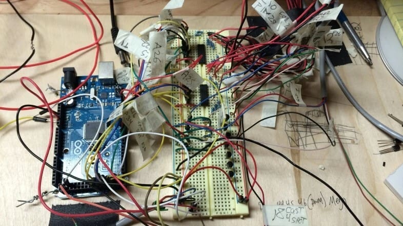
Answering these questions will help you find the right sensor for your project. There are countless versions that can work in almost any application. Before building the final project, however, make sure to try the circuit on a breadboard first so any problems can be easily fixed.

License: The text of "Hall Effect Sensor & Arduino: How to Make Them Work" by All3DP is licensed under a Creative Commons Attribution 4.0 International License.