How to Use FreeCAD for 2D Drafting & Design

FreeCAD is free and open-source modeling software. Among its capabilities, you can do traditional 2D drafting. Learn about FreeCAD 2D!
FreeCAD is 3D modeling software that runs on Windows, Linux, and MacOS. It’s completely free, which makes it popular for independent workers, hobbyists, startups, and all users who have a limited budget but need capable software.
2D CAD is commonly associated with software like AutoCAD, and it consists of drawing the projected views of a model, instead of the whole model.
In this article we’ll cover some features, including the drafting configuration, different line types, widths, colors, adding dimensions and annotations, modifying said annotations, creating circles and patterns, and other aspects of 2D drafting in FreeCAD.

Why FreeCAD?
FreeCAD is organized in layouts called “Workbenches”. These workbenches depend on the function you want to accomplish and on the tools you will need. For 2D CAD, FreeCAD has its own drafting workbench called “Draft”, in which you can do traditional 2D modeling.
In FreeCAD’s case, as you can take your model from one workbench to the other without any extra work, you can also use the Draft workbench to sketch your 3D model, as FreeCAD is a parametric drawing software where you go back and forth between 2D and 3D to complete your model.
Even though FreeCAD is functional enough for 2D drafting, it’s not centered around it and may not be as developed as other software, especially if your aim is to do highly complex 2D drawing. In that case, we would recommend using other 2D CAD software instead, like AutoCAD or LibreCAD. However, FreeCAD is a good starting point to learn the basics or work on projects if you’re under a tight budget.
Setting Up the Drafting Workbench
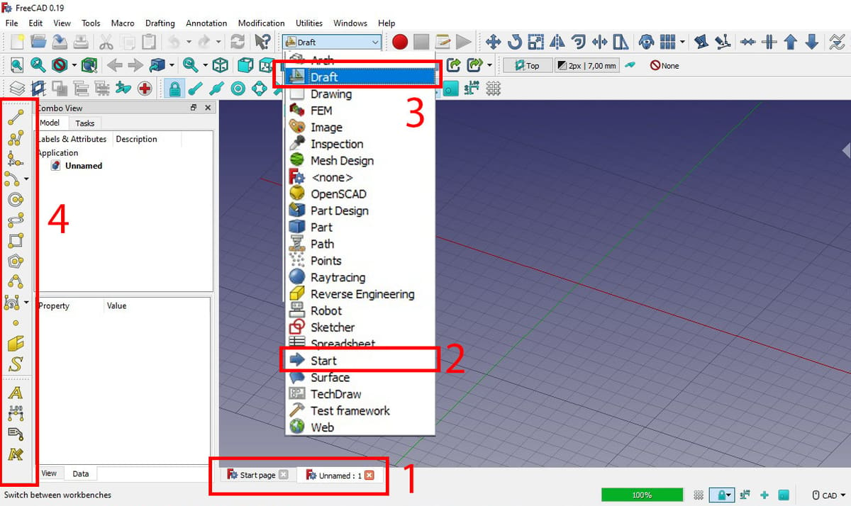
When you launch FreeCAD, you land on the starting page, which you can see as an open tab on the bottom of the workspace (1). Here, you have the option to create a new project.
Once you’ve started a new document, you still don’t have any useful tools to start modeling, whether in 2D or 3D. This is because you’re still in the Start workbench (2). To start drafting, switch over to the Draft workbench (3).
You can personalize the layout in any workbench, which can be helpful. There isn’t a specific recommended configuration, but when you first start, you can’t see some sets of tools because they’re cluttered together on the left. We recommend organizing them so that all tools in a set are visible at once (4). The next time you open a previously customized layout, the new configuration should remain.
Starting Configuration
FreeCAD is set by default in a 3D space, so before getting started, as you’re looking to use it for a 2D drawing, you have to choose a view to work on. There are two ways to do this: you can choose one every time you work on a project, or you can set one up for all occasions.
Depending on how often you’ll be drafting in 2D, this second option may be more convenient. It may also make more sense to select the top view as your drafting view, as it resembles looking at a piece of paper from the top. To better understand this, you can see the view options signaled in the image above.
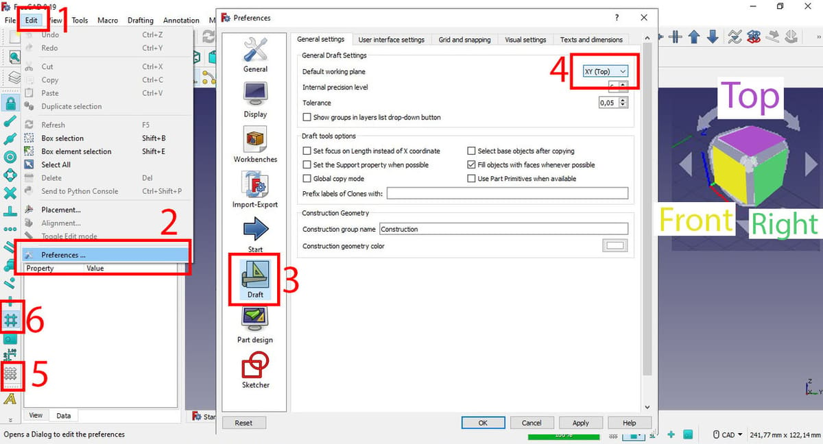
To set your drafting view for all occasions, click Edit (1), Preferences (2), and then Draft (3), and select the top view (4).
Additionally, you may still see a blank workspace. This is because you also have to activate the grid (5), and additionally you can activate the snap-on function (6) to snap to the grid.
The grid tool displays a grid on the workspace that may make it easier for the user to see dimensions or draw by using the snap-on function. The snap-on function snaps lines of your drawing to vertices of the grid, making it easier to achieve exact drawings visually.
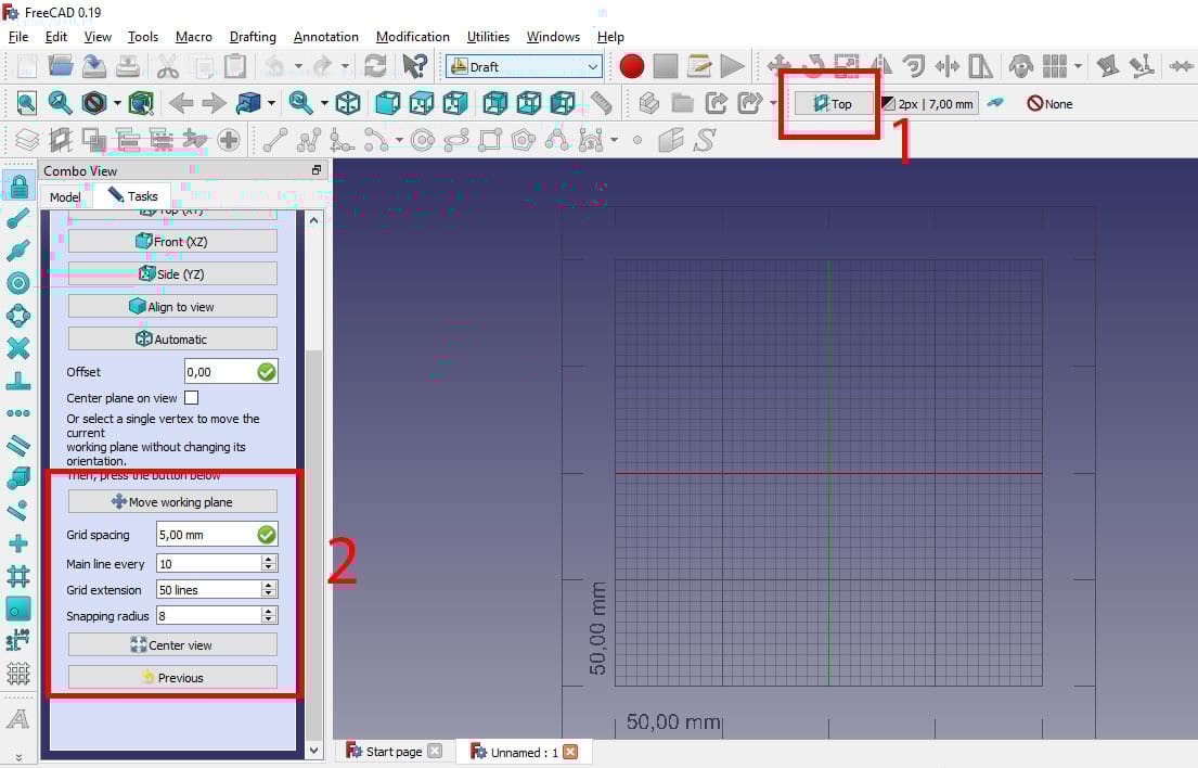
By selecting the view configuration (1), you can change grid settings like the size of the grid and the lines’ spacing (2). Depending on your project, the requirements may change.
If, for example, you’re designing a small part with dimensions smaller than 10 mm, setting the grid spacing to 1 mm would be more useful, but if you’re going to be working on a scale of tens of meters, setting it to half a meter might be best.
Modifying a Drawing
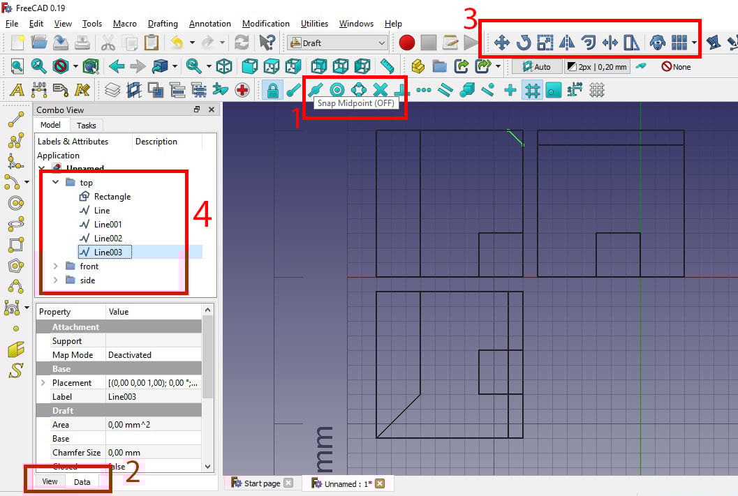
If you come from a background of AutoCAD, the symbols for transformation and drawing tools will be similar. But even if you don’t, what each symbol does is pretty easy to guess: the line symbol is for creating lines, the rectangle for creating rectangles, and so on. Even for symbols you don’t know, if you hover on the button, FreeCAD will show you the name of each tool and shortcut (1).
When you select any tool, you can see its properties to the left. There are two tabs of properties, “View” and “Data” (2). You can use these tabs to change some important properties. For example, for lines, you can change the thickness and type (e.g. solid or dashed), as shown in the image above, and also the color.
Modification tools (3) include: Translate, rotate, scale, mirror, offset, trim, stretch, duplicate, and pattern.
To scale a line or a set of shapes, select them, choose the scaling tool, and then type the percentage of scaling you wish to do. To move, select the shapes you want to move, then choose a reference point to move from, and a final point to move to. That reference point is usually the outermost corner of a shape or the center of a circle.
You can select all shapes existing in your drawing with Ctrl+A, or deselect them with the same command. To further organize your hierarchy, you can create groups to organize lines and other elements (4). Keep in mind that selecting a group doesn’t necessarily select the objects inside it, for example, when moving them.
Creating Drawings
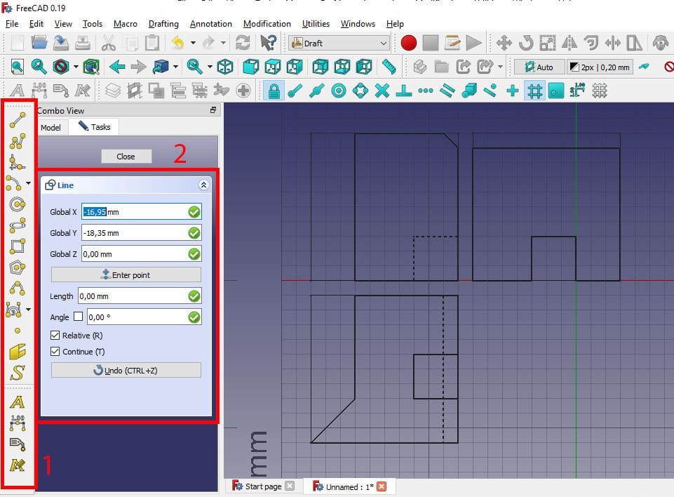
Drawing tools (1) include: Line, polyline, fillet, arc, circle, ellipse, rectangle, polygon, spline, bezier curve, point, and shape from text, which means converting text into a sketch entity.
Creating shapes is pretty much the same as using any other vector drawing program. Even if you’ve only ever created a line in MS Paint, it follows the same principle: You select the kind of shape you want to create, and for shapes like rectangles and lines, you select the starting point. Then, for the finish point, you have the option to select it visually on the workspace, or you can type its coordinates in the property box to the left (2).
To create circles, you first indicate the center point and then the radius, whether by indicating the outermost point of the circle in the workspace or by typing in the radius in the property box.
Remember that all lines created are fully constrained so you have to correctly draw the circle from the start or use modification tools later on.
A Note on Creating Drawings
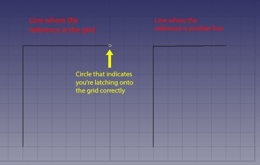
FreeCAD has a slight issue that will hopefully be improved in future versions. The snap feature is too sensitive to other objects, and lines have a certain thickness, so if you need to snap a point to a grid vertex where there’s already a line, the program can tend to accidentally snap to the line instead of the grid. This can mean that lines that have been created incorrectly end up not perfectly vertical or horizontal.
If the grid is selected correctly, you’ll see a small circle surrounding the vertex instead of the line.
Additional Tools
Pattern
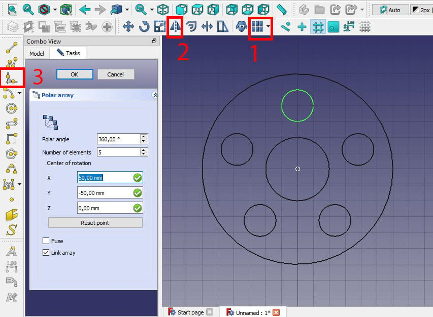
A pattern (1) is an efficient way to replicate a drawing as many times as you need, in different directions depending on the type of pattern you choose. The most common patterns are linear and polar.
To create any pattern you must first select the shape you want to make a pattern from. In a polar pattern, you must also choose the center point of the pattern, in which the radius of the patterns is the distance from that point to the center of the shape to be replicated. Then you must indicate the number of replications you want.
When creating a linear pattern, you simply choose the X distance and number of elements for that coordinate, and the Y distance and number of elements for that coordinate.
Mirror
As the name indicates, the mirror (2) function creates a reflection of a selected shape. Using it is fairly simple: Select the shape or shapes you want to mirror, then select a reference line to mirror across. The reference line must be straight, it can’t be curved.
Fillet
Fillets (3) are a method of efficiently creating rounded corners. To create a fillet you must select two intersecting lines and set a radius. Additionally, you can choose to delete the original corner and to create a chamfer instead of a fillet. If choosing a chamfer, it will still use radius as a parameter, and only chamfers at 45° will be created.
Setting Up Dimensions
Before creating a dimension, make sure that your dimension settings are correct. What dimension settings you have ultimately depend on what technical norms you’re following, according to your company or personal preference. That said, a good rule of thumb is to check that the dimensions’ scale is appropriate to your drawing’s size. If your drawing is too big and you use the default dimensions, they may simply be too small to be read.
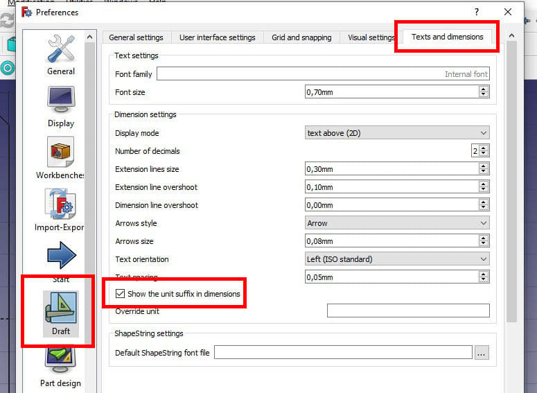
To change your dimension settings, go to “Edit > Preferences > Draft > Texts and dimensions”. There are many settings you can customize, but one important part to note is whether to check or uncheck the “Show the unit suffix in dimensions” box. Dimension settings depend on the norm, but aspects such as arrow length and size are not as easy to catch as written units. So it’s especially important to make sure that you have the units display set according to the norm you’re following (for example, ISO).
Adding Dimensions
To add a dimension (1), select the two points you want the dimension to measure. For example, if you want to add a dimension to a line, you don’t select the line, but its two vertices.
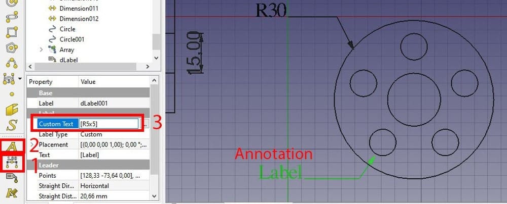
To add a radius, you don’t actually use a dimension, but an annotation tool (2). Annotations display “Label” by default, and you can modify that in the Data section of the properties by changing the text inside the brackets (3).
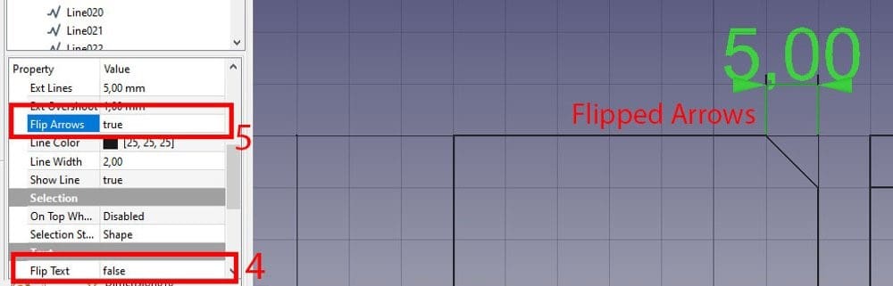
Finally, if the text is on the wrong side of the dimension line (commonly, it should be above for horizontal dimensions, and to the left for vertical dimensions), you can fix that with “Flip Text”=True (4), in the property box.
If the dimension arrows are not properly distinguishable because the dimension line is too short, you can flip them outwards with “Flip Arrow”=True in the property box (5).
With that basic knowledge, you’re all set to do 2D drawing in FreeCAD!
License: The text of "How to Use FreeCAD for 2D Drafting & Design" by All3DP is licensed under a Creative Commons Attribution 4.0 International License.