Estlcam for CNC: Beginner’s Guide

Estlcam is easy-to-use software that converts both 2D and 3D designs into CNC programs. Read on for tips on how to get started!
Estlcam is a computer-aided manufacturing (CAM) program that allows users to turn 2D drawings and 3D models into machine-readable G-code. This brilliant project was created by Christian Knüll, and its popularity has skyrocketed since it debuted in 2014. Perhaps the most attractive characteristics of Estlcam are its simplicity and low price.
If you’re a beginner in CNC milling, you’ve probably been frustrated by the complexity (and ungodly prices) of many CAM programs. Estlcam solves these frustrations by presenting users with an extremely intuitive user interface at a price of around $60.
The program sticks to the basics. Simply import a 3D file (such as an STL) or a 2D file (such as .dxf, .svg, .png, .gif, or .jpg), generate toolpaths, export the G-code – which is referred to as a “CNC program” in Estlcam – and start cutting. In this article, we’ll guide you through Estlcam’s basic features and provide tips on settings along the way.
If you’re curious about giving Estlcam a try, there’s an unlimited trial period that’s completely free. However, you might consider buying the license because users have reported it can get quite slow after a while. The software is available on the Estlcam website, and depending on your computer’s processing capabilities, you can download either the 32-bit or 64-bit version.
Speaking of cutting… what are we waiting for?

Getting Started
The interface and setup of Estlcam are brilliantly intuitive. Upon finishing download and installation, you’ll be asked to select your preferred language as well as length and feed rate units.
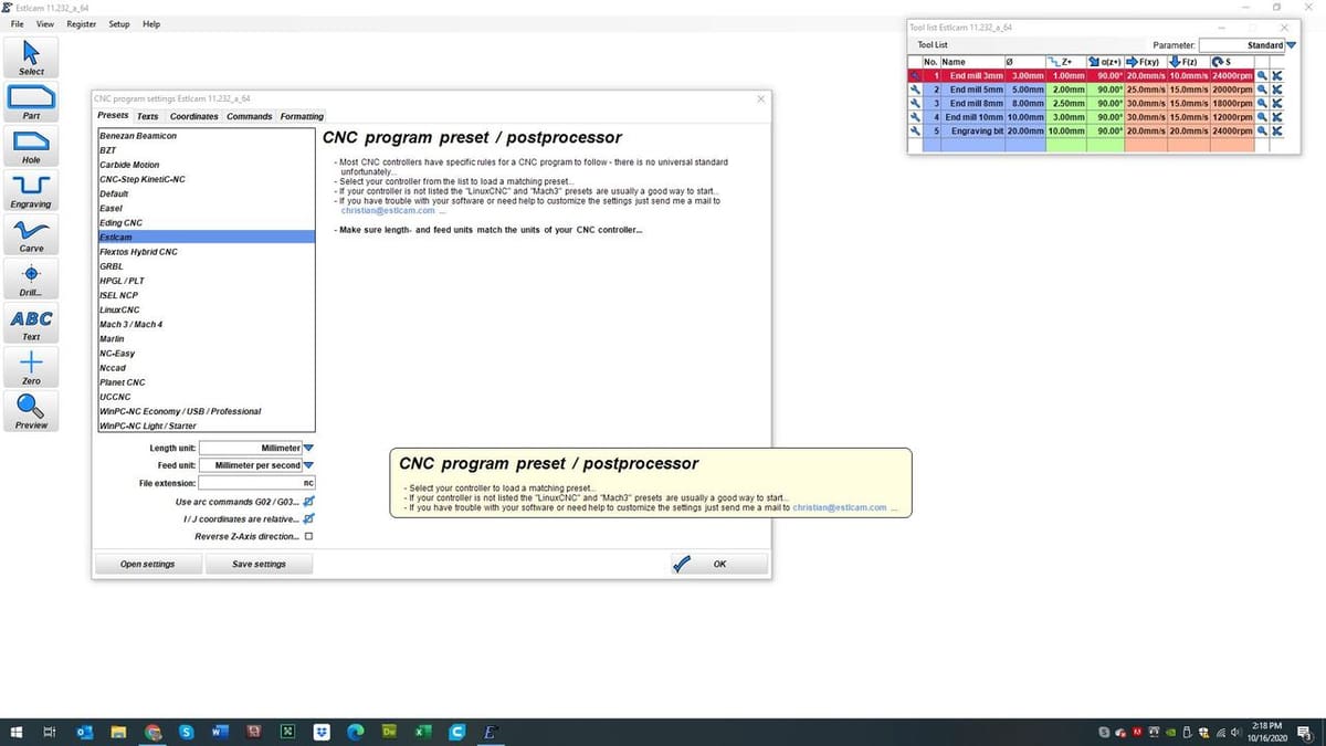
After this initial setup, you can further edit preferences under “Setup” menu on the main toolbar. Here, you can configure settings according to your CNC machine’s controller, G-code flavor, coordinate system, spindle, and various accessories, such as custom teach pendants and Z-offset touch plates.
Estlcam’s UI is very clean and simple. On the left-hand side of the window, you’re presented with options to define the tolling operation you wish to perform. Estlcam can print designs as parts, holes, engravings, or carvings. The “Preview” icon allows you to preview your toolpaths.
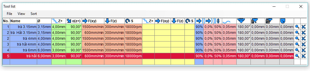
The final main component of Estlcam’s interface is the tool list, which is on the upper right-hand side of the window. In the tool list panel, you can order or edit existing tools, or define custom tools based on your particular bits. The standard tool list only shows basic settings. If you want to define more advanced features of your bits, simply click the wrench icon to the right of your tool.
Importing Files
Like most programs, it’s possible to import a file into the Estlcam workspace by selecting “Open” from the options in the File menu. This will automatically launch your file explorer in which you can select the file you wish to import.
Estlcam will automatically initiate a project appropriate to the file type when you import a file:
- DXF, PIT, or HPGL: Initiates a 2D or 2.5D project
- E25 or E19: Resume editing a 1D, 2D, or 3D Estlcam project or export as a CNC program
- STL: Opens the 3D milling workspace
- PNG, GIF, or JPG: Opens the picturing milling module
- GCODE or NC: Launches the CNC controller
Once you have your file of choice successfully imported into Estlcam, the real fun can begin. The first step is to properly position, scale, rotate your model. When you import a 3D file, a small window opens with movement, rotation, and scale tools. If you’re working with a 2D drawing, these tools will appear next to the left-most toolbar.
In order to properly position your machine’s cutting head before milling, it’s important to note the position of origin. To move it in the 2D workspace, simply click the “Zero” icon on the left toolbar. Then, click a point on the plane that you’d like to set as your new origin.
Selecting Tools
Selecting the correct tool for each operation is key to a successful CNC project. Chamfer bits are perfect for V-carving but do a sorry job of milling flat-bottom pockets. Thick endmills are essential to making voluminous cuts quickly. However, they are hopeless tools when it comes to sharp corners or details with any detail.
You get the point: Knowing how to pick the right tool is almost as important as knowing how to turn your CNC mill on. Let’s take a look at how to tell Estlcam which tools you want to use.
- View list: When you open up the program, the “Tool list” panel should also open in the program’s window. If you don’t see this list, you can either click F1 on your keyboard or select “Tool list” from the View menu on the main toolbar.
- Expand or collapse: To expand this list, click the View tab in the “Tool list” panel and check (or uncheck) the tool definitions that you wish to include or eliminate from the tool list.
- Defining tools: You can simply input your desired values for the tool’s settings, which are listed in the various columns of the table. Clicking the tool icon in the last column of each tool directs you to advanced settings and allows you to customize the default, finishing, drilling, and trochoidal milling parameters, for example.
- Selecting tools: This is the easiest: Click the tool you want to use, and you’re done!
Now that we have a handle on how to select and customize tools, let’s start defining cutting paths for them.
Defining 2D Toolpaths
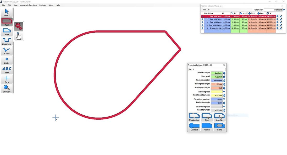
Estlcam provides users with six different toolpath options: “Part”, “Hole”, “Engrave”, “V-carve”, “Drill”, and “Text”. To define a 2D toolpath, you simply select the appropriate toolpath icons from the toolbar on the left-hand side of the window, click on the contour of your choice, and customize a few settings. We’ll go over contouring and customization in more depth below.
Defining Contours
You can either define a contour using automatic or manual shape detection.
- Automatic shape detection: This option allows you to select a path from a 2D file you’ve imported. You’ll experience errors if this path has gaps or overlaps.
- Manual shape detection: This option gives you full control over the definition of your toolpath. You’ll be able to select and connect points to modify an imported contour or to create a new one entirely from scratch.
Customizing Settings
There are several customizable settings for each toolpath type. Here’s a list with a description of the main settings so that you can adjust each of them appropriately:
- Toolpath depth: This setting defines the depth of your cuts. You can either input a unique value for this setting or select the “Ask Later” option to define a uniform depth for each tool path when you export as a CNC program.
- Start level: This setting defines the starting level of your tool path. Total depth is calculated by the sum of “Toolpath Depth” and “Start Level”.
- Machining order: Machining order determines a toolpath’s position in the sequence of cuts. Toolpaths with positive values (in order from smallest to largest) will be machined first, followed by all cuts with “Machining Order” set to “Automatic”. Next comes toolpaths with negative values (in order from smallest to largest). Finally, finishing operations, chamfers, and threads will be performed.
- Holding tab length and height: These settings define the size of your holding tabs.
- Finishing tool and allowance: You’re able to define a finishing tool (leave it blank if it’s not applicable) and the X- and Y-axes’ cutting allowance for the finishing bit, if applicable.
- Pocketing strategy and angle: You can select the appropriate pocketing strategy and direction angle for your part or hole. Estlcam provides thorough descriptions of the available options, which include “Linear”, “Parallel”, “Peel”, “Peel from Inside”, and “Peel from Outside”.
- Holding tab: Holding tabs can be inserted by clicking points on the part where the tabs should be located.
- Start function: You can click a point on your contour to define the tool’s point of entry.
- Lead-in: This function defines a point of entry and the starting point of the cut on the contour.
- Overcut: Sharp corners are impossible for inside cuts due to the diameter of tools. If you need a part to fit another and are worried that the rounded inside corners will prevent this, simply define the corners you want to be overcut.
- Pocket function: This function removes all the material within a selected contour in order to form a pocket.
- Island function: This function removes all the material between a standing part and an outer boundary.
After customizing these settings, you’ll be quickly on your way to a beautifully machined part.
Defining 3D Toolpaths
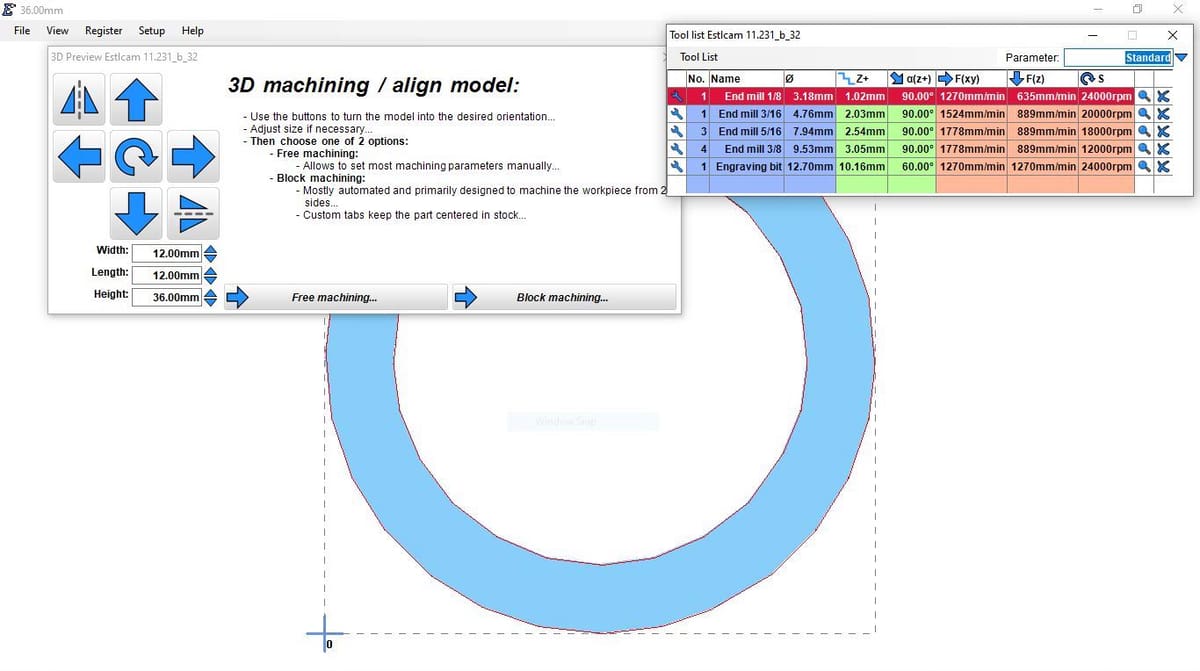
Defining toolpaths for 3D models is rather simple, though perhaps slightly less intuitive than the 2D process. Begin by opening an STL file to initiate Estlcam’s 3D milling environment. Select your desired units, then properly align and position your model with the scaling, rotation, and mirroring tools that pop-up upon opening a 3D model.
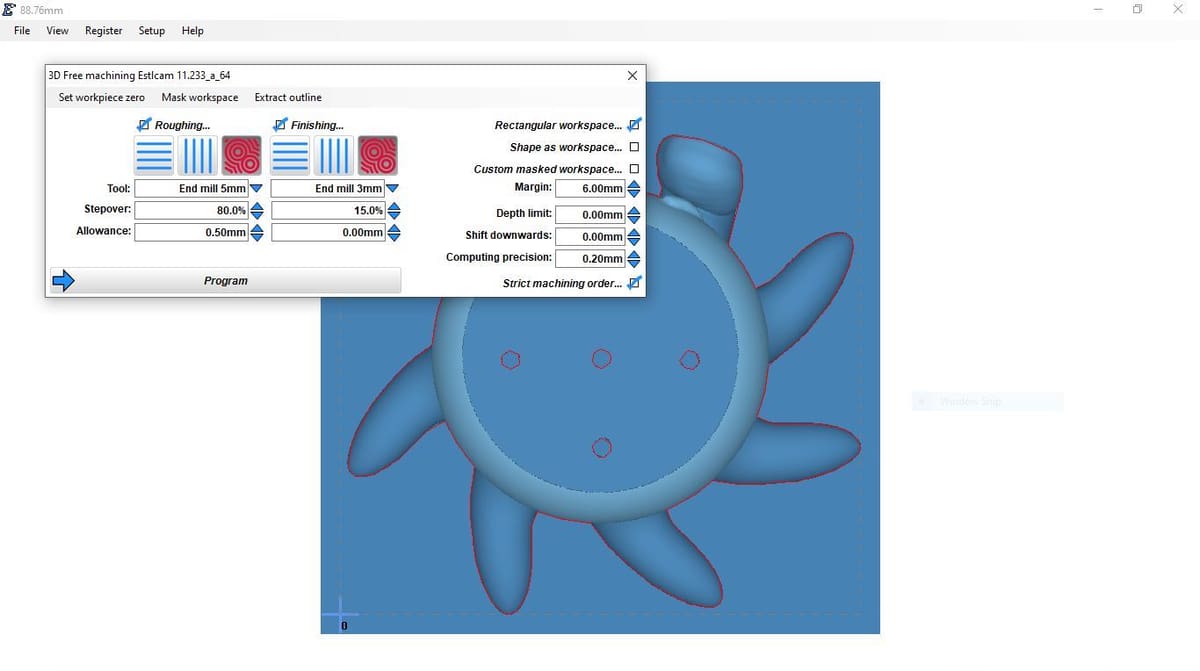
Let’s take a look at the various settings in the 3D milling panel:
- Set workpiece zero: Setting the workpiece zero is extremely important. If this zero is improperly defined, it’s extremely easy to waste stock material or even cause your CNC to crash.
- Mask workspace: If you don’t need to mill certain parts of your 3D model, you can mask your workspace with a DXF file. Masked features will be ignored.
- Extract outline: 2D milling is much faster (for your computer and CNC), so, if you have a fairly simple outline on your 3D part, try extracting this outline to cut down on superfluous processing and machining time.
- Roughing and finishing: 3D milling is typically completed in two phases: roughing and finishing. The roughing pass, which is usually completed with a larger tool, removes a majority of the material. The finishing occurs with an often smaller tool for more precision and better surface finish.
- Consider allowing a 0.5 mm or larger allowance for the roughing pass so that the finishing tool can achieve the best possible surface finish. (80% is a great starting value for the roughing pass’ Stepover setting while 15% or lower is great for the finishing process.)
- Use parallel milling for simple, boxy models.
- Contour milling is best for detailed or rounded models.
- Workpiece settings: Esltcam provides workpiece settings to define the shape and size of the stock. Maximum depth allows the CNC to cut only to a certain depth on the model. By shifting your model downwards, you can ensure that the top face is milled accurately and smoothly.
- Computing precision: This value determines the dimensional precision Estlcam will achieve when processing the model. 0.2 mm is a good starting place as it’s a nice balance between accuracy and low-processing (machining) time.
After you’ve defined all of the 3D toolpath settings, click “Program”. This will allow you to watch a simulation of the milling process and save your design as a CNC program, which will direct the operations of your CNC machine.
Exporting
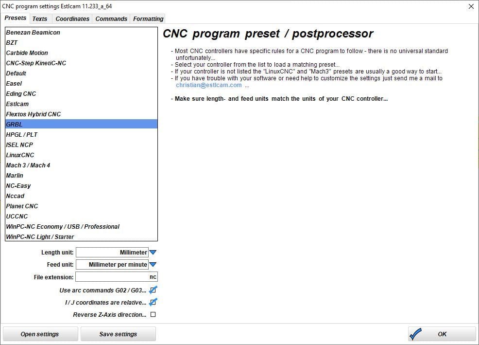
Having defined your toolpath(s), you can now export your project as a CNC program. Given that you’ve already selected your preferred units, CNC controller, and G-code flavor in the initial setup, the CNC program exporting process is super simple:
- Click the “File” tab on the main toolbar
- Select “Save CNC Program” from the menu and voila!
You can choose the folder in which the program will be saved, and Estlcam will automatically export your project as a GCODE file in your predefined format. If you set “Cutting Depth” to “Ask Later”, Esltcam will open a window with a prompt to input the desired depth for the toolpath(s).
Having exported your program, you’ll be forwarded to a simulation window in which you can rotate the view of your cuts and run a simulation of the milling process. This simulation can be fast-forwarded or re-winded with the given double-arrow buttons.
Now that you have a basic overview of Estlcam’s tools, settings, and operations, you have everything you need to get started creating your own machined parts. We hope you found the overview helpful and wish you happy cutting!
Lead image source: Christian Knüll via YouTube
License: The text of "Estlcam for CNC: Beginner’s Guide" by All3DP is licensed under a Creative Commons Attribution 4.0 International License.