Dimensions in AutoCAD: All You Need to Know

Dimensions form a crucial element of any technical drawing. Read on to learn about the different dimension commands in AutoCAD!
The purpose of any technical drawing is to convey all the relevant details about the project to the concerned individuals. This means the drawing must be informative and precise.
Using the dimensioning features in AutoCAD allows you to illustrate the dimensions of each element in your drawing. Instead of needing to measure and label each line, circle, or arc individually, these features assign dimensions automatically to the selected element.
AutoCAD provides a host of dimension tools you can use to show the measurements in your drawings. These tools allow you to dimension each element precisely the way you want it. You can highlight angles, lines, radii of circles, arc lengths, and much more.
Here, we’ll be looking into everything you need to know about dimensions in AutoCAD, including the required commands.

Purposeful Dimensions
Using dimensions in a drawing is vital for accuracy, interpretability, and comparability. Clearly labeled dimensions provide an instant source of crucial information. Before we dive into the commands, let’s look at why dimensions are not to be overlooked in your AutoCAD skillset.
Precise Manufacturing
Whether you’re an engineer, architect, or designer, a key reason you’ll be sketching out a drawing is for it to be used as a reference for manufacturing or construction. So, the drawing needs to be as precise as possible. Dimensions are used to show various features of the workpiece, more than just its basic measurements. You can highlight the tolerance, fits, surface finish required, and many other things through dimensions. A well-detailed drawing will result in a good result.
Convenience
The mark of a good designer is how easily their drawings can be interpreted by the viewer. A thoroughly dimensioned drawing aids in visualizing the size of different views more precisely. Nobody wants to calculate or assume the measurements of design elements: Assigning dimensions to each element removes any potential ambiguity and assists in smooth production.
A Dimensioning Family
In your drawings, you’ll need to know which type of dimension should be attached to each element. Using the incorrect sort of dimensions can unnecessarily complicate your drawings and even increase the workload. There are several categories of dimensions in AutoCAD, so let’s understand the major players.
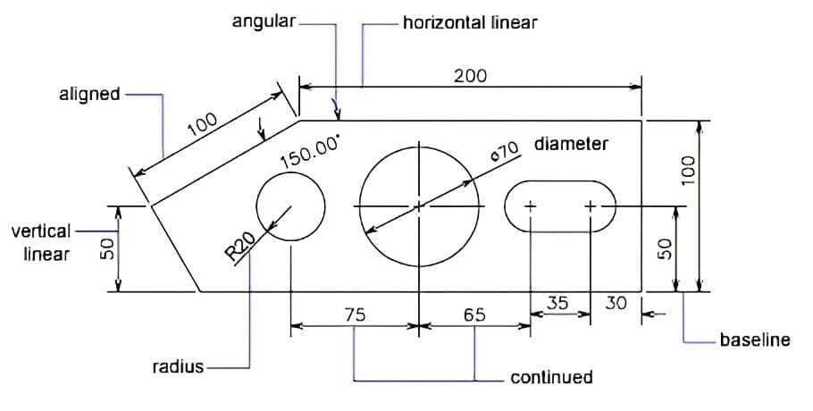
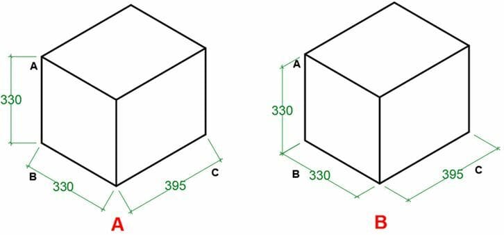
Linear Dimensions
This is the most commonly used type of dimension in AutoCAD drawings. It assigns dimensions to the lines or points that are perpendicular or horizontal to the coordinate system. So, if you have a square in the drawing, the linear dimension type is used to show the sides of the square.
- Command: DIMLINEAR
Aligned Dimensions
This type of dimension is a subcategory of linear dimensions, but with an important distinction (and its own command). Aligned dimensions measure the inclined dimensions in your drawings. Just like the previous example, in the case of a square, you can use this type to indicate the diagonals of the square. Chamfers in the drawing can be annotated using a combination of linear and aligned dimensions.
- Command: DIMALIGNED
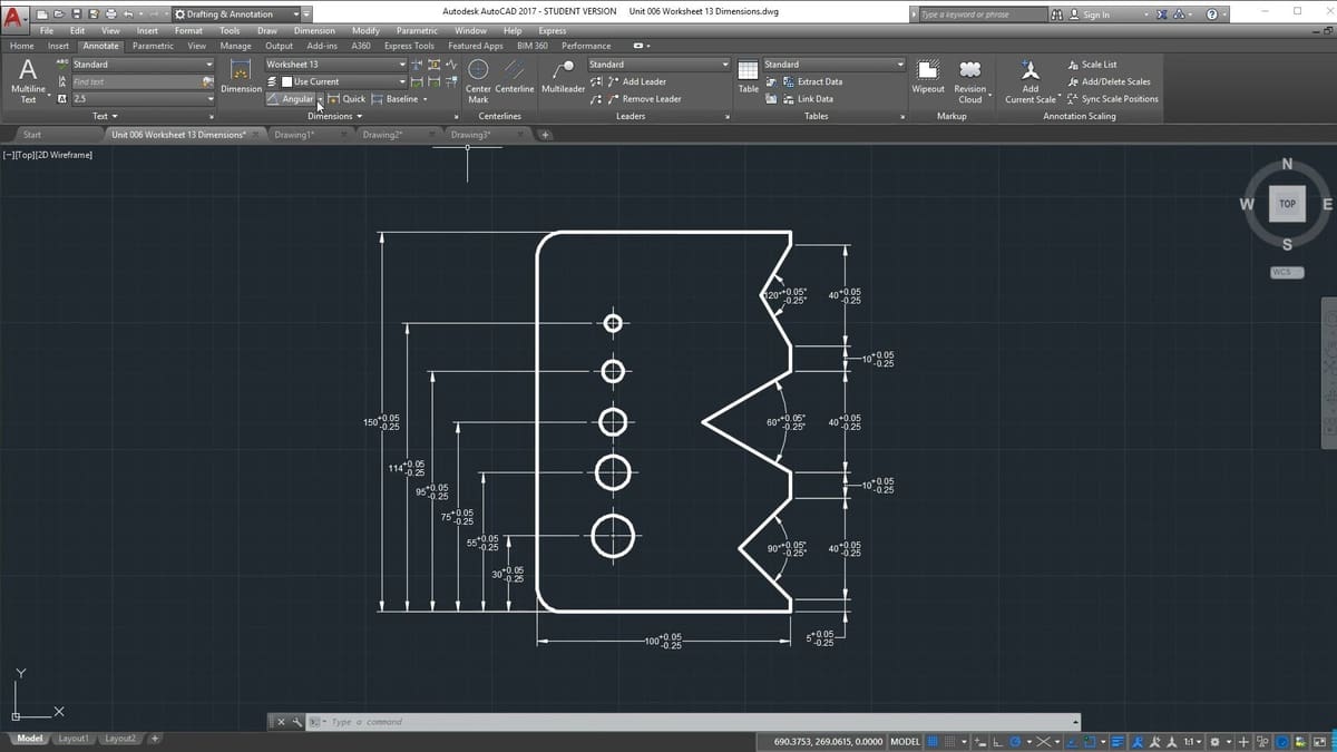
Angular Dimensions
You can show any angles in your drawings using this style of dimension. It can be used flexibly to show the angles of any arc, between two points, or between two lines.
- Command: DIMANGULAR
Ordinate Dimensions
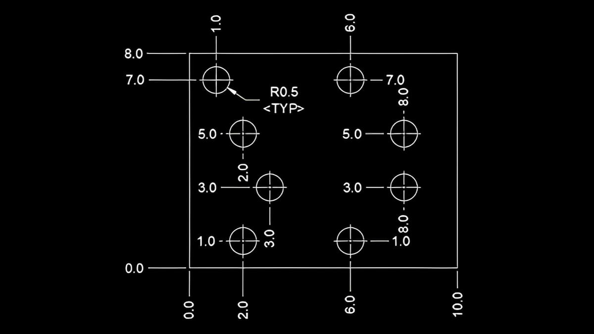
Ordinate dimensions don’t indicate the measurements of any individual elements in your drawings, but instead show a position on the XY-plane. So, using the ordinate dimension feature, you can find the exact location of any point from an origin.
- Command: DIMORDINATE
Radial Dimensions
Radial dimensions are used to denote the dimensions of any circular elements in the drawing. You can use this type of dimension to fully annotate any circles, arcs, or curves. A good technical example is dimensioning fillets in drawings. In AutoCAD, there are three main ways that you assign the radial dimensions to your drawings.
Diameter: You can apply this feature to show the diameter dimensions of a circle.
- Command: DIMDIAMETER
Radial dimension: This feature indicates the radius of any circle or an arc.
- Command: DIMRADIUS
Center mark: The radius and diameter features don’t show the center point of a circle. Use this feature to show the center of the circle or arc.
- Command: DIMCENTER
Arc Length Dimensions
Arcs can be dimensioned in many ways. You can indicate their angle, radii, or diameter, depending on the application of the arc. The arc length command is used to show the length of the arc or the polyline that’s used in your drawings. One practical application of this is annotating cams used for motion transfer. By knowing the arc length, you can calculate the travel distance for the cam.
- Command: DIMARC
Editing Dimensions
AutoCAD lets you take dimensioning one step further by editing dimensions after they’re assigned. You can change their positions and locations, and change how you want them to appear in the drawing. There are two ways you can edit the dimensions in AutoCAD.
Dimension Edit
This feature is used when you have a lot of dimensions in your drawings. Using this feature, you can neatly format the dimensions and make them appear clearer. It allows you to edit any assigned dimension. You can rotate the text at an angle, add another dimension, or change the value of the dimension. You can also make the dimension oblique by using this feature. This comes in handy in isometric drawings.
- Command: DIMEDIT
Dimension Text Edit
This feature is another way to change the position of the dimension text within the specified parameters. You can adjust the dimension text to appear on the left, right, or at the center of the element. Just like the previous one, you can also change the angle at which you want the text to appear. These two commands overlap each other a little, but in the actual use case scenario, you’ll understand that these are indeed two separate dimension editing features in AutoCAD.
- Command: DIMTEDIT
Dimension Styling
The editing feature lets you make small adjustments to the dimensions. It doesn’t change any properties of the dimensions but adjusts the position of the dimension text. However, if you want to customize the appearance of the dimensions, there’s a command for that, too! Using the dimension styling feature, you can create customized arrow types, choose your text font, text size, and much more.
- Lines: You can customize the appearance of the dimension line and extension lines. You can assign different colors to them and change their line types.
- Symbols and arrows: This allows you to change the size and types of arrowheads and leaders in the drawing. You can customize how you want the center mark and arc length symbol to appear.
- Text: This option lets you configure the dimension text. You can configure the size of the text, its color, placement, alignment, and even the text font using this command.
- Primary units: You can choose the primary type of unit you want a dimension to appear in. This also allows you to choose the precision of the units, that is, how many decimal places to display.
- Alternate units: This option lets you display the same dimension in any alternate units you want. So, you can display a particular dimension in two different formats. This comes in really handy when professionals from different fields refer to the same drawing.
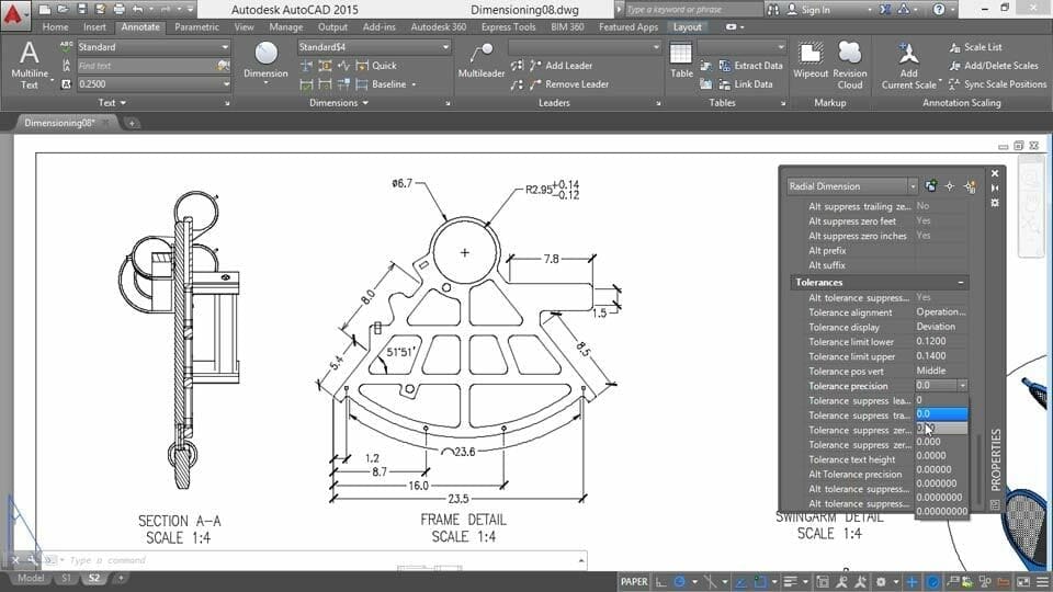
- Tolerances: In product manufacturing, having the tolerances of a certain dimension can aid in the production process. You can choose to display the type of tolerance you want to assign to your elements from limits, deviations, and symmetrical tolerances.
You can access all these options in the dimension style manager. You can create a new style or change the existing style.
- Command: DIMSTYLE
Dimensioning Tips
Even with all the commands under your belt, there are a few tips that can help you ace the dimensioning game in your AutoCAD drawings.
- Always try to display maximum information using minimum dimensions. You should not repeat or duplicate any dimensions unnecessarily. Too much information will make your drawing appear cluttered and difficult to read.
- If it isn’t specifically mentioned, choose a horizontal alignment for your dimensions. This makes it easier for others to read them and eliminates the need to rotate the paper with every other inclined line.
- You should denote entire circles using the diameter dimension type and half-circles or arcs using the radius style of dimension.
- If you’re not mentioning the unit in your dimensions, always add a note to your drawings that indicate the units in which the drawing was sketched. This can be another way to avoid clutter.
- Always keep the dimensions equidistant from the edge of your drawings. This will make the drawing appear a lot cleaner.
Final Thoughts
We’ve seen that you can add detail and accuracy to your AutoCAD drawings by really understanding dimensions in AutoCAD. We’ve just skimmed the surface of what’s possible, but you can find loads of tutorials and guides that go into more depth about each dimension feature we’ve seen. Even if you find yourself in a rabbit hole of information, you’ll find out some amazing things that’ll aid you in AutoCAD drawings.
License: The text of "Dimensions in AutoCAD: All You Need to Know" by All3DP is licensed under a Creative Commons Attribution 4.0 International License.