CAD / CAM / CAE: The Differences – Simply Explained

If the three-lettered acronyms CAD, CAE, and CAM have you confused, read on for our explanation of these unique yet related processes.
Computing Power
Acronyms are quite helpful in a professional environment, but their ubiquity can become overwhelming. In the world of 3D printing, engineering, and manufacturing, you’ve likely heard of CAD, CAE, and CAM at some point. But do you know what they mean?
All three relate to a category of software tools that assist hobbyists and professionals in creating and producing goods. The “CA” is the same in each acronym and stands for “computer-aided”, while the final letter describes specifically what it supports: design, engineering, and manufacturing, respectively.
CAD is perhaps the most popular of the three, first established back in the ’80s, and now is a must-have tool for most (if not all) engineering disciplines. The ability to design parts and products digitally has truly changed the way we make things. It’s also provided the platform to integrate computational engineering analysis and to improve the way things are produced.
In this article, we’ll explore the differences between CAD, CAE, and CAM in the context of product development. Let’s go through some of the steps required to design and produce an air compressor rotor and establish how these software tools relate to each other in real life.
CAD: Designing
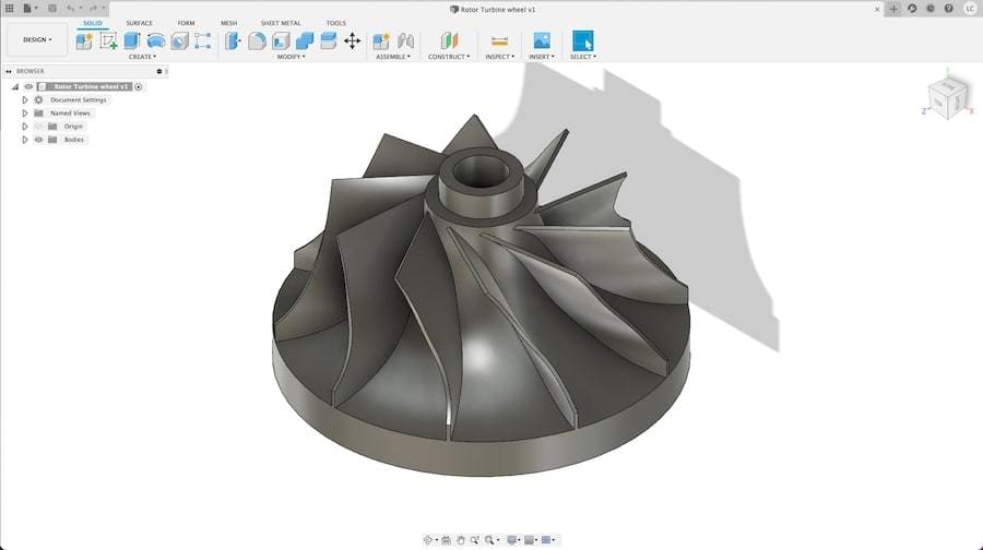
CAD, or computer-aided design, can be defined as the computer technology used for design and technical documentation that replaces manual drafting. A digital drawing board provides flexibility with quick design interactions and keeps the documentation consistent between different designers and engineers.
How It Works
At first, CAD tools only replaced 2D manual drafting, which by itself is already a great feat. Imagine how products were created before CAD: massive rooms full of designers hand-drawing and detailing complex things such as entire buildings or cars.
Over time, though, digital design has literally gained another dimension with the arrival of 3D modeling techniques, including methods such as solid and surface modeling, as well as 3D modeling software. The 3D environment developed for CAD tools provides the foundation for other computer-aided tools, which we’ll explore more later.
In general, CAD greatly increases quality and productivity, as well as enabling fast collaboration between teams around the globe. Its main gains are reducing development cycles and shortening new products’ time to market. A high level of standardization was also achieved as CAD effectively automates much of the creation process.
Popular Software
Although SolidWorks is one of the most popular CAD programs used professionally, there are many others. For example, CATIA is considered the standard for development in the automotive and aerospace industries. For hobbyists, Autodesk’s Fusion 360 is a popular option because it offers free accounts for personal use.
Real-World Application
For our rotor development example, a design team would use CAD tools for the initial product conceptualization to the final product design. For assemblies, which is not our case, CAD would also provide the full list of parts and fasteners required, known as the bill of materials (BoM).
Next, we need to make sure the rotor will work as intended.
CAE: Testing
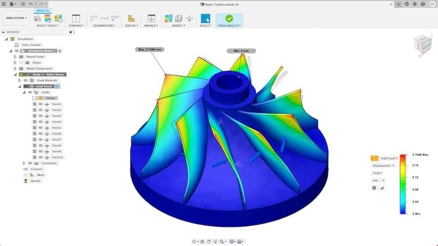
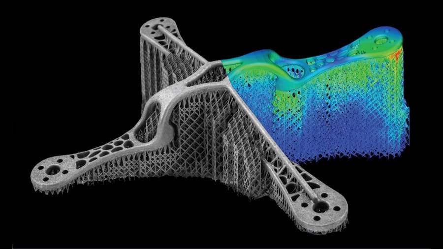
Computer-aided engineering (CAE) is an umbrella term that encompasses the use of computational tools to support different types of engineering analysis. In practical terms, CAE tools check the robustness and performance of parts and products by simulating real-world conditions.
This becomes a critical part of the initial development stages when design choices can be supported by data acquired through digital testing. Moreover, CAE tools help engineers validate and optimize their designs throughout an item’s development roadmap.
How It Works
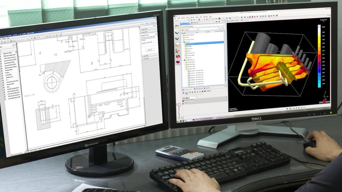
CAE tools are often integrated with CAD because they require 3D models and a platform to perform the analysis. In general, these tools run simulations of many sorts – structural analysis, thermal distribution, fluid flow, among others – according to what is expected of the part.
The results should provide enough data for engineers to go back to the CAD file and create better and more effective products before they’re even produced. In addition, less physical prototyping and testing are required, severely cutting down on development costs.
Popular Software
Altair’s HyperWorks is one of the most well known CAE programs, followed closely by Ansys’ varying package solutions for different types of simulations. The aforementioned Fusion 360 also offers some CAE tools, although those are only available in the paid and educational versions.
Real-World Application
For our compressor rotor development, the team would use CAE software together with CAD during the design stages. Eventually, the final design would be validated prior to prototyping and, finally, manufacturing.
CAM: Manufacturing
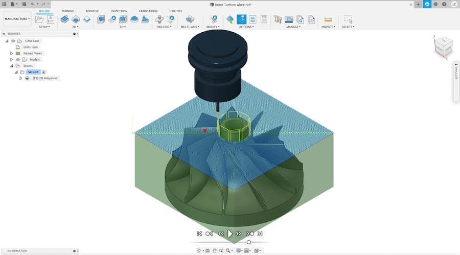
CAM stands for computer-aided manufacturing, which is essentially the automation of manufacturing processes. CAM software literally controls each and every aspect of a CNC system, be it for machining, milling, laser-cutting, 3D printing, or any other numerically-controlled manufacturing system.
Before CAM, skilled machinists were required to manually program CNC manufacturing systems, an endeavor that involved plenty of experience. Now, CAM software streamlines this process by automating all programming required to accomplish even the most complex tasks.
How It Works
CAM provides all the benefits of automation: efficiency, consistency, and most importantly, speed. Toolpath optimization allows parts to be produced as fast as possible, a feat that only the most experienced machinists were capable of.
CAM deals exclusively with manufacturing, although minor design changes can be still made to the product when important insights are drawn during CAM analysis. The removal of small details or sharp corners, for example, might improve the manufacturing process, while any performance penalty can be verified through CAE.
Popular Software
Mastercam, PowerMill, and BobCAD-CAM are all great examples of professional CAM packages used across different industries and manufacturing processes. Once again, Fusion 360 provides a CAM environment for up to 3-axis control.
Real-World Application
With our rotor design already validated, the team would come up with the best way of producing it using CAM tools and the machines available. The faster the better, although without becoming detrimental to part quality. CAM software is definitely the best tool for helping engineers find that sweet spot.
That's It?
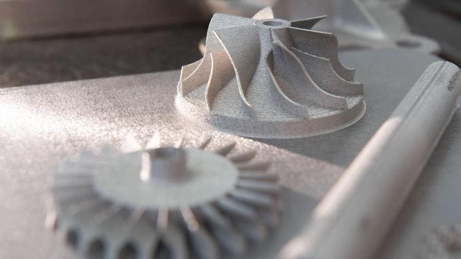
While there’s obviously much more work involved in developing and producing a compressor rotor, we hope it’s clear how important computer-aided tools are for such processes. More importantly, though, we believe this article has shone a light on the differences between CAD, CAE, and CAM, once and for all.
Lead image source: India Education
License: The text of "CAD / CAM / CAE: The Differences – Simply Explained" by All3DP Pro is licensed under a Creative Commons Attribution 4.0 International License.