Blender: Blueprints – How to Set Them Up

2D technical drawings can work as references for modeling. Read on to learn how to use Blender for blueprints.
Once upon a time, the world communicated design almost exclusively in 2D. Today, 3D modelers use powerful tools in their craft. But we don’t start from thin air. We need references, inspiration, or a beginning. Whether modeling flowing organic shapes or precision geometry, having good reference material is essential.
That’s where blueprints and Blender come in. Blender is a program used for creating and animating 3D models, among other undertakings.
In this article, we’ll go over what blueprints are and some sources that can be used to set them up for 3D modeling. Then we’ve got a tutorial on how to set up a propeller blueprint.
While it’s an introductory tutorial, we’ll work on the assumption that you’ve got the basics of Blender covered. In case you need to do a deeper dive into how Blender works, here’s our beginner’s guide.
What Is a Blueprint?
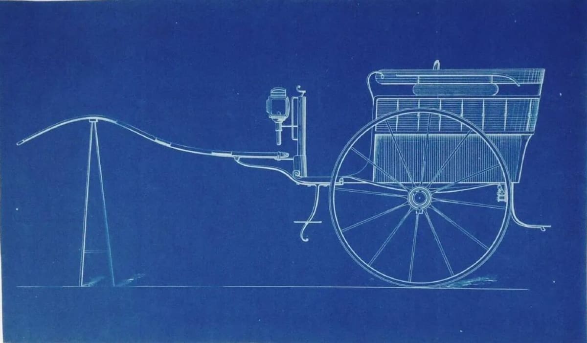
Originally, a blueprint was a 2D technical drawing. More specifically, it was a copy of a hand-drawn original, and the reproduction process resulted in a blue negative copy. Fresh blueprints were cold to the touch and had a strong ammonia smell. With the smell long since gone, the term lives on to describe 2D technical drawings.
In 3D modeling, “blueprint” describes the use of 2D reference drawings imported into modeling software, which allows you to create a model on top of the blueprint. In general, these references are views of the same object from multiple orientations.
Why Use Blueprints
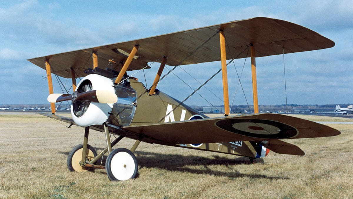
Suppose you need to create a 3D model of something that you have limited access to, maybe a historical airplane in a museum. Even if you have access to it, it’s hard to take hundreds of measurements for your research. By using readily available 2D drawings as a reference, you don’t need to crawl around a priceless museum exhibit with a ruler.
The number of images needed to start modeling depends on how complex the object is. Something like a logo might only need one, while a car would need a front, side, rear, and top view to define its shape.
Many 3D modeling programs have a way to bring multiple 2D images or blueprints into the 3D environment. The images are imported as planar objects and scaled and aligned into position.
Orthographic Projection
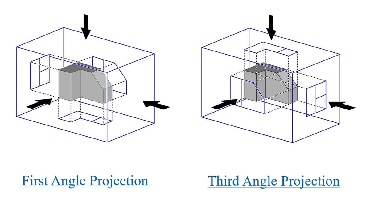
Having a basic knowledge of how orthographic projection works will help avoid confusion. This is especially true if you’re working with abstract, unfamiliar shapes. 2D technical drafting standards differ slightly in different regions of the world. Perhaps the most significant difference is the direction in which views are projected. Third-angle projection is used in North America and first-angle projection is used in Europe.
You should be able to identify which projection style is being used in the drawing; this will help to interpret a blueprint drawing. With third-angle, the view is placed between the object and the observer. With first-angle, the view is placed behind the object.
You may already have a preference that feels more natural to you, so you can place your images in your modeling program using either method. It may be slightly better to use the same method as the source material. For seasoned designers, switching to a different projections style can be like switching which side of the road you drive on; beginners have the advantage of not having to retrain their eyes.
Resource Material
If you’re using the blueprint method to model, it’s likely that you’re recreating an object from references. Choosing reliable references can be difficult, so it’s useful to get familiar with the object through research. Even if you know the subject well, use photos to remind you of the little details. Online image searches will lead to a lot of good material. Pay particular attention to the sites where images come from, as these often have some history behind your chosen subject that may add more to your modeling process and final product.
The technique works the same for drawings or photos, although images from blueprints will have true orthographic images with no perspective distortion. For best results, use drawings for scale and photos for visual cues.
Working with Drawings
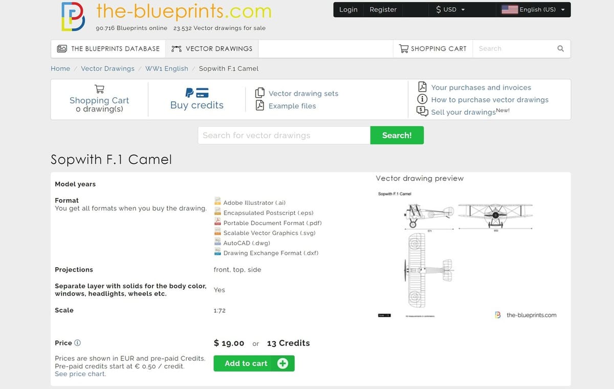
Not all blueprint-style drawings are design documents – those are rarely publicly available. However, artists’ recreations are usually fairly accurate and widely accessible. Sites like The-Blueprints.com or BlueprintBox have thousands of them. You can do a Google image search and select “Line Drawing” under Tools > Type, to find specific items. Add search terms like “design”, “dimensions”, or “blueprint” to get more details. Government agencies are a little-known source of technical images, too.
Paper or Mylar blueprints can be scanned or photographed, though be aware that the digital image may have some distortion caused by the camera angle or paper’s humidity. You can compensate for this in a photo editor or in Blender by using scaling tools. Knowing a few dimensions in each direction will help you verify the accuracy.
Working with Photos
Setting up blueprints for modeling doesn’t have to be used exclusively with line art. Photographs can work well, but you have to account for perspective, as this will affect how accurately you can line up and eventually model the design. A photo taken from far away with a zoom lens will have less perspective distortion than a close-up.
It’s also important to account for how clear photos are, and whether there are irrelevant objects or a crowded background that may represent an additional challenge for the setup of the images before modeling.
Adjusting 2D Images Before Import
You want to be able to easily pick out features in each view; for this reason, high contrast works best. A photo editor can make the useful data stand out by altering a few settings, and images can be cropped to a convenient size. If you have a multi-view drawing with an identifiable origin, add a mark in that location; it can be used later to align views.
Blueprints in Blender
Now that we’ve seen how different sources can be used, let’s put them into use. Blueprints can be set up in Blender by either importing images as planes or by adding reference images. The image as planes technique is more about importing 2D images as part of a scene. The reference image technique is specifically catered to blueprints setup. We’ll focus on reference images because it has a faster workflow and doesn’t require any add-ons.
The basic workflow is similar to most 3D modeling from 2D references – even the medical imaging industry uses similar techniques with programs like 3D Slicer. However, the names might be different depending on the program you’re working on; for example, in Fusion 360 the images are called canvases.
Running through an example will help get acquainted with the procedure. This tutorial has some twists that you may not anticipate at a first glance, and often the hardest part is visualizing the 3D shape in your mind.
To help you get your bearings, we’ll set up a blueprint of an airplane propeller from the 1920s. As mentioned, we’ll be using Blender for this tutorial, but many of these steps are similar to other 3D modeling software.
Reference Images
In Blender, a reference image is imported as a special kind of empty. Empties, which have no real geometry, are what CAD users call coordinate systems: it’s a way to have a reference position and rotation.
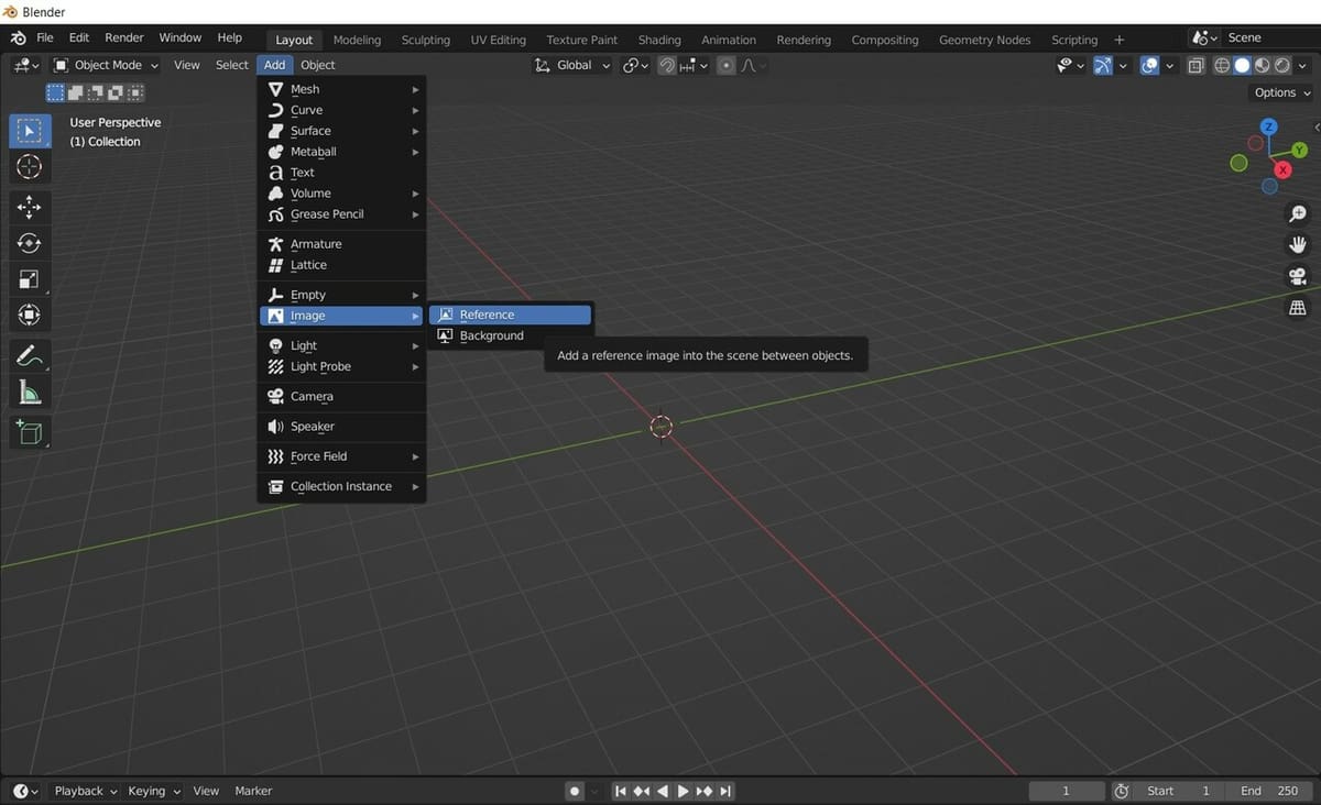
A reference image is a type of empty with an image attached to it. It can be a little confusing in Blender because there are two menu picks to add an image-type empty. They’re essentially the same, but one doesn’t prompt you to retrieve the image, you must add the image later. We’ll use the “Add > Image > Reference” menu option, which does prompt for an image.
Reference images can be moved, scaled, rotated, or manipulated like most other objects. They have some unique properties to change how they look at different view angles. These options can make them not visible under certain conditions or occlude one another.
Empties’ properties include:
- Location: The X, Y, Z position values
- Rotation: The X, Y, Z rotation values
Reference images’ properties include empties’ properties plus:
- Depth: Adjusts how the reference image occludes other reference images
- Side: Makes the reference image only visible from the front, back, or both
- Show in: Shows or hides images based on viewing modes or angles, including orthographic, perspective, or only axis-aligned
- Opacity: Allows you to make the reference image transparent when checked
Now that we’ve covered all the basics, let’s work on how to set up blueprints in Blender.
Step 1: Research
An image search for “vintage aircraft propeller blueprints” is the start of a rabbit hole that leads, among other options, to NASA. They have old reports on aircraft design research, and our search led us to the NTRS (NASA Technical Reports Server).
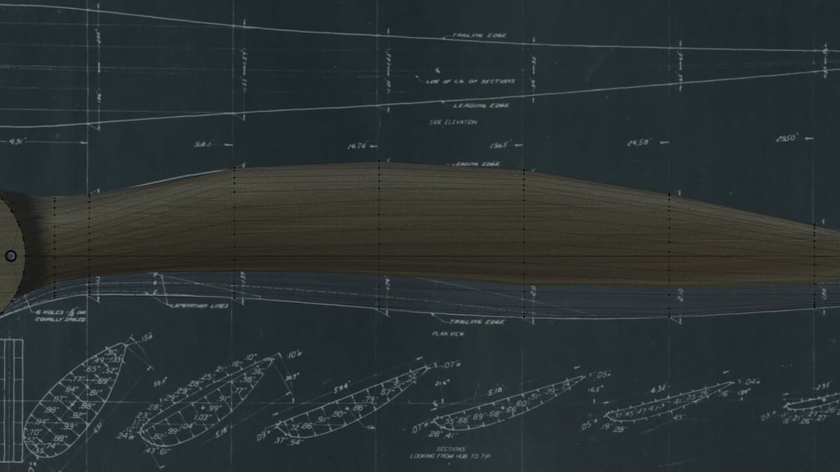
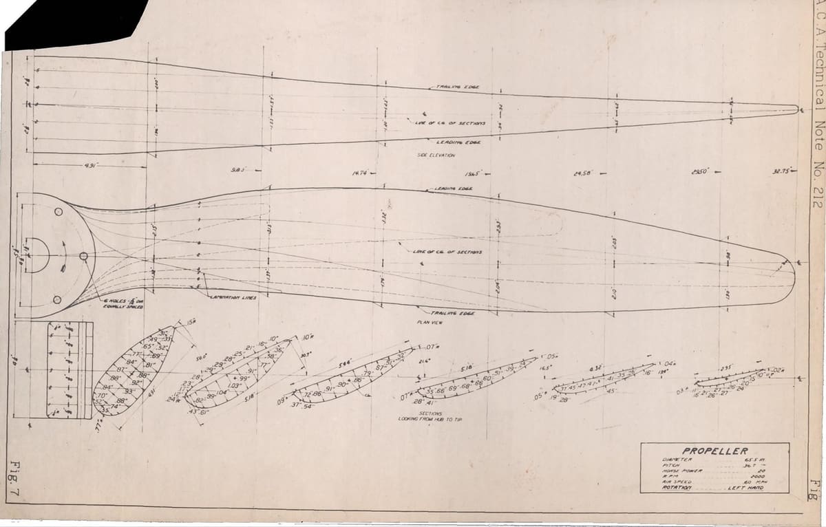
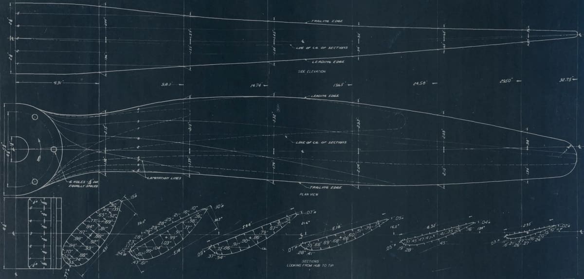
Looking through the NTRS, there’s a report about propeller design. On the last page is a blueprint that’s an absolute gem; it has a front and side view with dimensions and a bonus of cross-sections in two directions.
Cross-sections are sliced views that isolate details of a particular plane. Aircraft and ship production drawings often have evenly spaced cross-sections to describe irregular shapes.
Step 2: Prepare the Blueprint Image
Before bringing images into our 3D modeling software, we need to set up the reference images. Each view will be imported as a separate image file.
This blueprint is a single sheet image but is in a PDF document. To extract the image from the PDF, we have to save the last page as a JPEG file with Acrobat or similar software. If you don’t have that available, you can save a screenshot. Try to save the file with a high enough resolution to see the lines and read the text. Aircraft drawings like this were usually drawn at full scale and scanned at high resolution.
Now that you have an image file, use a photo editor to improve the quality. Keep the original file and make a copy for your edits. There’s no need to spend a lot of time here; we’re just making it easier to read and remove clutter.
Using a photo editor:
- Crop the blueprint to remove the border;
- Straighten to correct scan rotation;
- Increase the contrast and darken, and invert the colors if it improves readability.
Our sample blueprint was edited in Photoshop, and we opted for the following changes: Straightened, Invert, Brightness -32, and Contrast -18.
You may notice that our inverted image is the classic blueprint blue color. Back in the old days, blueprints were negatives of the original drawings. The inverted or negative color of blue is the color of old paper, which was so a copy of a copy looked like the original. This was either a lucky accident or the work of some very clever chemists.
Taking a close look at this blueprint we can see the quality is quite good, but notice that the vertical and horizontal lines have jogs in them. These are artifacts from when the original drawing was scanned, and we’re not going to correct those in the image. If you’re using Photoshop, there’s a straightening tool that does this automatically. Scanned documents will always have some distortion, but we can use the dimensions in the blueprint to verify and adjust the 3D model later.
We need to look at the blueprint and start to build the shape in our minds. This blueprint was created in North America, so it’s probably third-angle projection. There are notes on the drawing indicating the leading and trailing edges of the blade; we can use those to visualize the twisting shape.
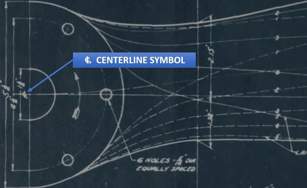
We can’t rely on the scanned image to be straight, so it’s important to choose some key features that can be used later to align views. We call these datums. For example, the blade centerline, visible in each view, and the axis of the propeller hub, are good reference lines.
While these steps would be the same for any 3D modeling software, we’ll be going into Blender specifics. However, other programs will use similar functions with perhaps different names. As mentioned Blender uses reference images, which are empty objects with an image associated with them; other programs might call these canvases, layouts, or import images.
Step 3: Start Blender
Open Blender and delete the default cube, camera, and light. Choose the units you want to work with – you can change the units of Blender to match the blueprint or use your preferred units and scale the part later. In this example, we’ll use the metric system and select cm; we’ll scale the model by 25.4 at the last step. In the Properties menu (right), select “Scene Properties > Units” and set your choices.
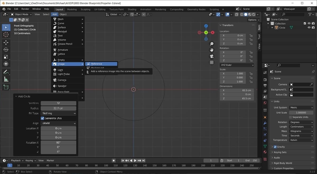
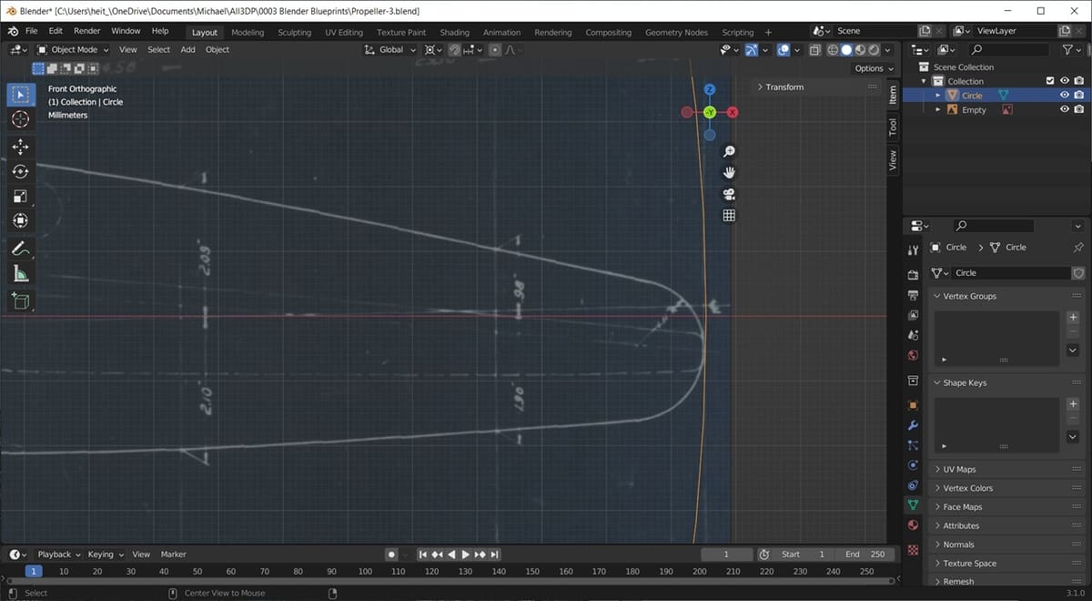
Reference images come into Blender at an arbitrary scale, so we need to create some simple size reference geometry to start. Looking at the original drawing, the upper left has a dimension of 32.75. That’s the radius of our propeller, and we can use this to scale the image. Create a circle the same size and with the same orientation as the propeller. Select “Add > Mesh > Circle”, and click the Add Circle tab in the lower left to change the radius to 32.75 and X rotation to 90°.
Referring back to the blueprint, we can see a view labeled “Plan view”. Plan view in this case means the main view, and it’s a good place to start. It has a lot of information on it that will help align other views. This propeller will be created facing the front as if we were looking at the front of the airplane. So that’s where the plan view goes.
Step 4: Add the First Image
When importing reference images, they’re going to be centered on the 3D cursor and oriented by the current viewport.
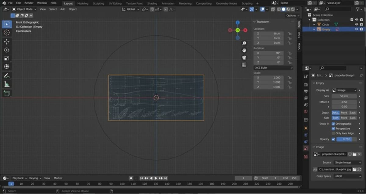
Go to the front view by pressing ‘1’ on the number keypad, or go to “View > Viewpoint > Front”. Select “Add > Image > Reference”, and select the plan view that we created before. Plop, there it is. However, it’s not quite where we need it, nor the correct scale. For now, we can change the size to something close to 50 cm. This can be modified in the Object Data Properties, the second option from the bottom in the Properties menu.
For more help getting started on Blender, you can use this cheat sheet to help you use the basic transformations.
When moving, rotating, or scaling in Blender, you can type the shortcut (‘G’, ‘R’, or ‘S’). Typing ‘X’, ‘Y’, or ‘Z’ after will isolate the transformation to a single axis. Typing a number after that will transform an object by a specific amount. For example, to rotate an object by 90° on the X-axis, type “R X 90”. Use the right hand rule to determine the rotation direction: Imagine your right hand grabbing the X-axis with your thumb pointing to +X, then your fingers curl around the axis in the +X rotation. Performing any of these transformations after a copy, “Shift + D” will transform the duplicate copy. You can then click anywhere in the viewing area to accept the transformation.
When duplicating or transforming objects, you can open the tab in the lower-left to type in values in the dialog box that opens.
Step 5: Align the Image to the Origin
Remember that we established the blade centerline and hub axis as datums.
Our image needs to be moved so that the hub center is at the origin and the blade centerline is along the X-axis. Let’s move it to the origin first. If it’s not already, have the viewport in front view by pressing ‘1’ on the number pad, or go to “View > Viewpoint > Front”. Select the image and press ‘G’ to move and drag the hub close to the origin. Zoom in closer and repeat with greater precision for a perfect alignment.
Next, we’ll scale the image. When you add an image, the size is arbitrary. For stand-alone objects, you may choose not to scale. However, suppose we plan on adding other parts to complete a full airplane. Building a plane with mismatched part scales will look odd and will make the whole process more complicated. You can skip this next scaling step if the part size is not important to you.
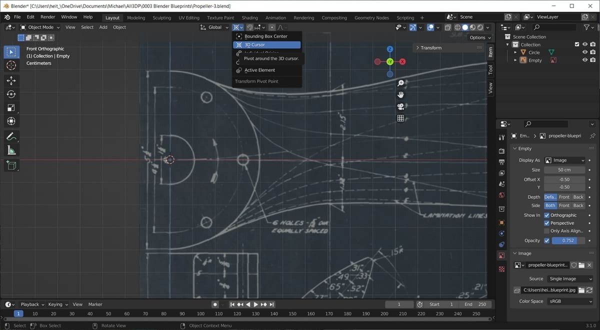
First, we need to change the behavior of the scaling to pivot around the 3D cursor. Otherwise, the propeller hub will move as we scale.
Select the Transform Pivot Point icon at the top-center of your screen, as seen in the image above, and then click on “3D Cursor”. Our handy dandy circle can be used to scale the image. Now, scale until the blade tip is just touching our reference circle. Press ‘1’ on the keypad to go to front view, or go to “View > Viewpoint > Front”, and select the image. Press ‘S’ to scale and drag the cursor to scale the image, until it reaches the reference circle, as seen in the image above. Hit the Enter key or left mouse button to accept the scale.
Step 6: Add the Second Image & Align
We want to copy this image and orient it to the top view. Select the reference image and hit “Shift + D” to duplicate it. Press ‘R’ to rotate and then ‘X’ to isolate rotation to the X-axis. Type ‘-90’ to align the view. So, the whole sequence is “Shift+D R X -90”, then press Enter. If this were a first-angle projection, we would rotate it in the other direction.
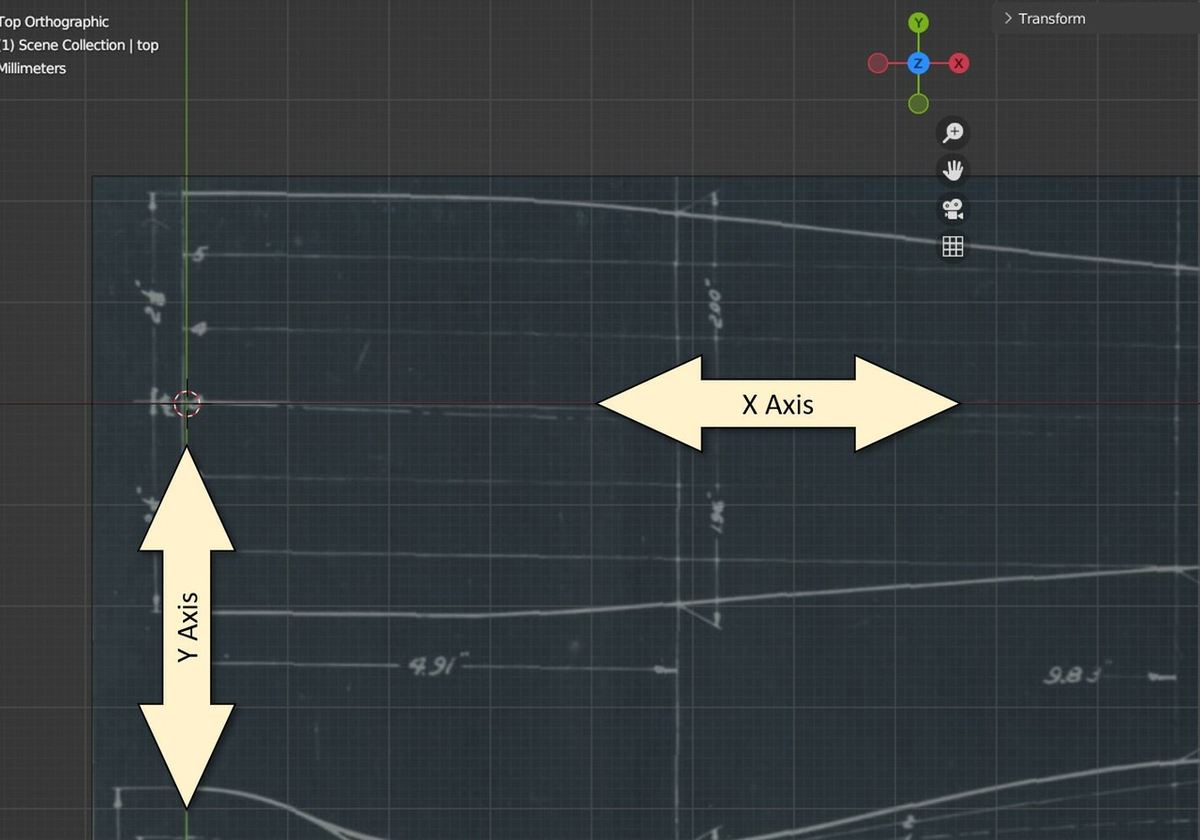
Now align the top view in the Y-direction so that the centerline is on the X-axis. Zooming in you can see the centerline symbol on the blueprint. Press ‘7’ to go to the top view, or go to “View > Viewpoint > Top”. Select the image and press ‘G’ to grab it, and ‘Y’ to move in the Y-direction. Move it until the centerline of the blade is on the red X-axis line.
Step 7: Add the Third Image & Align
Add the hub section image. Similar to the second image, we’ll copy this image (named Empty in the Outliner) and orient it to the side view. Select the first reference image and hit “Shift + D” to duplicate. Press ‘R’ to rotate and type “Z 90” to align the view, giving us “Shift+D R Z 90”, then Enter. Type “R X -90” to complete the rotation.
Notice that each time you transform an object, the Transform menu updates. If you prefer, you can change the location and rotation directly in the Transform menu (next to the Scene Collection).
Now align this view in the Y-direction so that the centerline is on the X-axis. Zooming in you can see the centerline symbol on the blueprint. Press ‘3’ to go to side view, or go to “View > Viewpoint > Right”. Select the image and press ‘G’ to grab and ‘Y’ to move it in the Y-direction. Move it until the hub center is at the origin.
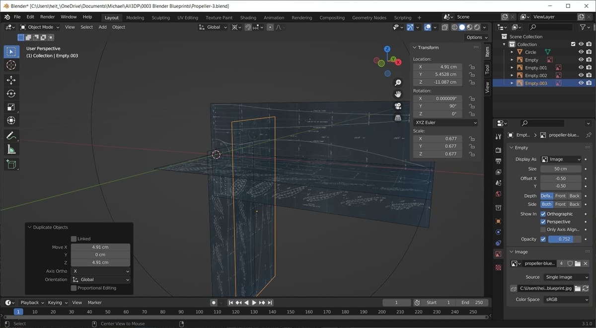
Add the rest of the cross-sections. Paying attention to the top view of the drawing, we can use the section dimensions to know how far to move each section into place. The first section is offset 4.91 from the origin. The side image will have a name like Empty.002, as it was the 2nd image created. Duplicate the side image, by pressing “Shift + D”. Type “X 4.91”, Enter, and “Z 4.91” in the duplicate dialog box in the lower left of your screen. Repeat this for the other sections using each of these values.
- X 4.91, Z 4.91
- X 9.83, Z 9.83
- X 14.74, Z 14.74
- X 19.65, Z 19.65
- X 24.58, Z 24.58
- X 29.5, Z 29.5
If done correctly, features on the views will be aligned. You can start to visualize the 3D shape. If something looks out of place, you can adjust the positions using the ‘G’ command.
Step 8: Get Ready to Start Modeling
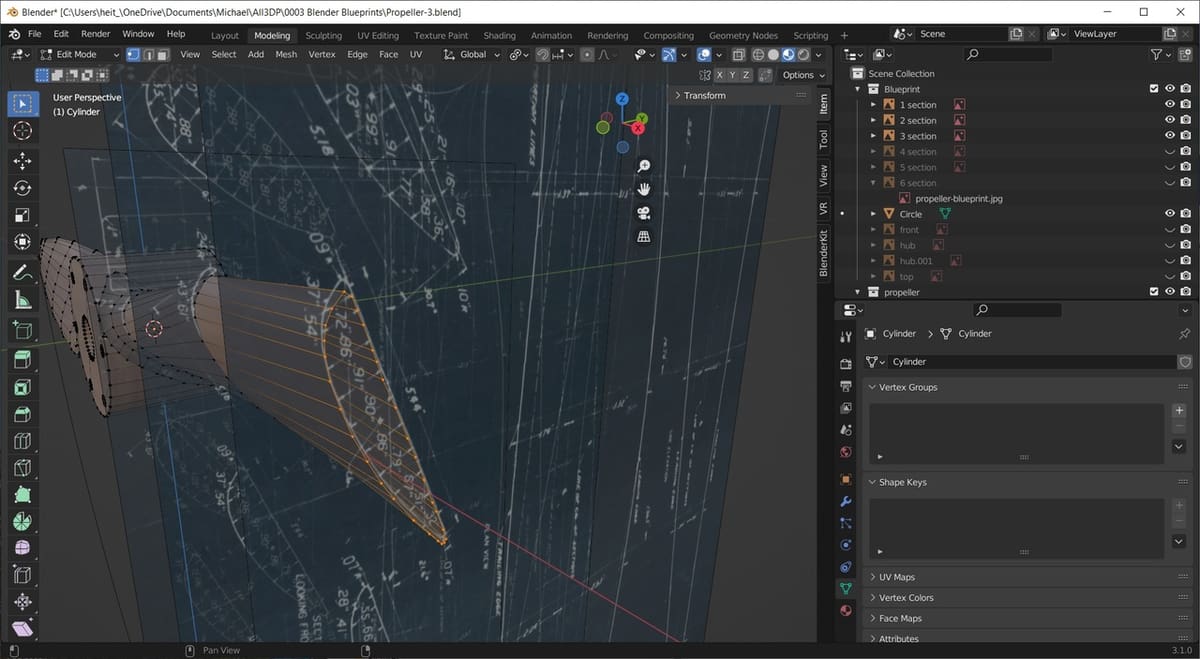
The blueprint is set up and ready to start modeling. It can get very cluttered, so hide the images that aren’t being used. You can do this by clicking on the eye symbol next to the object’s name in the Outliner, in the top-right menu. To make the objects visible again, simply click there again.
Create a mesh of the outline of the first section. You can extrude this first trace to the subsequent sections and adjust the vertices to match each section. Look at your model from the front, top, and side views occasionally to compare your model to the blueprint.
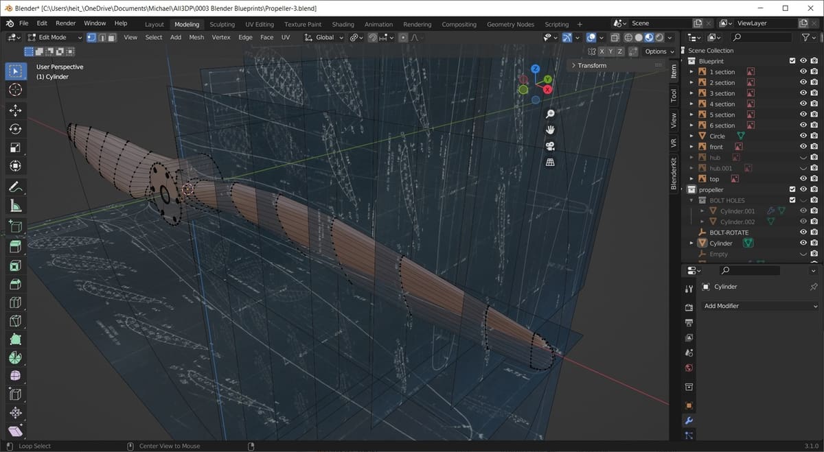
You can adapt this technique to suit your next modeling project. Try adding at least one reference image and notice how convenient it is!
License: The text of "Blender: Blueprints – How to Set Them Up" by All3DP is licensed under a Creative Commons Attribution 4.0 International License.