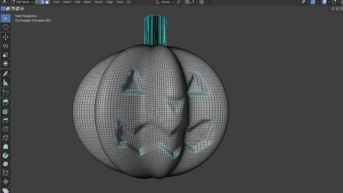
Blender Tutorial for Beginners: Make a 3D Printable Model, With & Without AI

Blender is the best free CAD software programs out there, but it's not easy to master. Using AI as a co-pilot can get you from idea to model faster.
Blender is free, open-source 3D software, and one of the most powerful programs for designing your own 3D-printable models. It takes time and patience to learn, but it rewards you with almost unlimited freedom to create exactly the models you have in mind.
Finding your bearings in the interface, while following a tutorial full of terms you’ve never heard, is challenging. Blender is not beginner-friendly CAD software so we’ve tried to make this tutorial as beginner friendly as possible, covering the basics every model starts with:
- setting up Blender for 3D printing
- finding your way around the interface
- moving and shaping objects
- carving details into a surface
Then you check the model with a free extension and export it as an STL file.
“But can’t AI design in Blender for me?”
This is an increasing common question so we gave it a go. We prompted an AI large language model (LLM) to write a Python script that you paste into Blender, to see how it compares to our “handmade” model. In this tutorial you build a jack-o’-lantern from scratch, check that it is printable and export it for your slicer.
This guide uses Blender 5.2 LTS. If you have an older version, some menus will look different.
Getting Started
Before you model anything, install Blender, set it up for 3D printing and get to know the interface.
Installation
The first step is downloading and installing Blender on your computer. For detailed instructions on how to do it, check out the online Blender Manual. This manual also has a lot of other helpful information about the different parts of Blender.
You can install Blender on Windows, macOS, and Linux. The download page lists all the available options in a drop-down menu, and you’ll also find the list of previous versions as well as the option to try out experimental builds.
Blender Experimental is a program that contains the latest unreleased versions of Blender with new features and fresh bug fixes. However, these might be unstable, and it’s suggested that they not be used in production environments. Before you download your version of choice, make sure to check out the minimum hardware requirements.
Open a New File
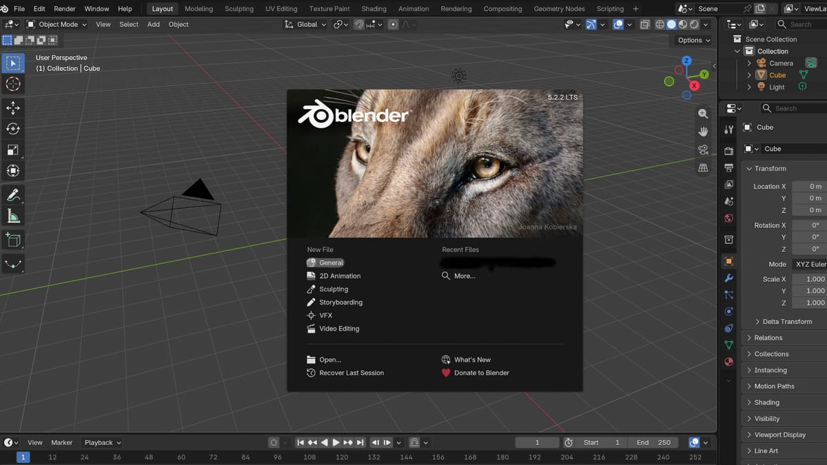
When you open Blender, you see the splash screen. Under “New File”, select “General”. It opens a scene with a cube, a camera and a light. Before you change anything, take a quick tour of the interface.
User Interface
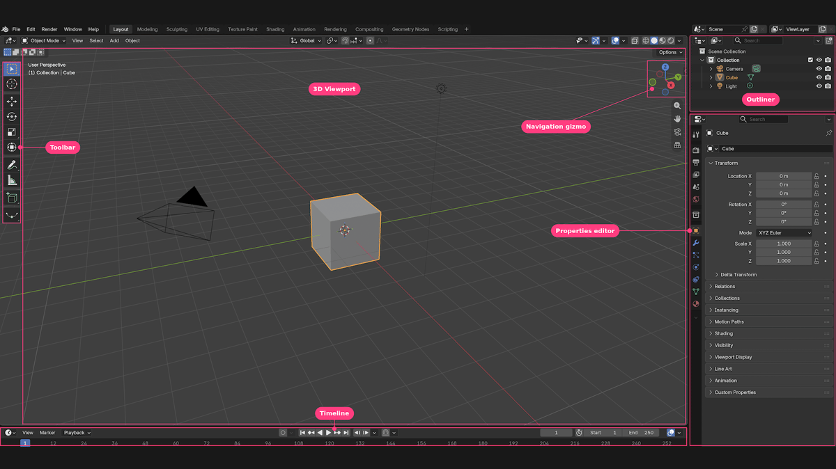
The default Layout workspace has six areas you will use:
- 3D Viewport (center): where you model. The header above it holds the mode menu (Object Mode, Edit Mode) and the View, Select, Add and Object menus.
- Toolbar (left edge of the viewport): Select, Cursor, Move, Rotate, Scale and other tools.
- Outliner (top right): a list of all objects. Each object has an eye (visibility) and a camera (render) icon.
- Properties editor (below the Outliner): tabs for tool, render, output, scene, object, modifiers and more.
- Timeline (bottom): animation. You don’t need it for 3D printing.
- Navigation gizmo (top right of the viewport): the colored X, Y and Z axes. Click an axis to jump to that view.
The workspace tabs along the top (Layout, Modeling, Sculpting and so on) switch between layouts for different jobs. This tutorial stays in Layout.
Deleting the Camera and Light
The camera and light aren’t needed for 3D printing, so delete them. Keep the cube for now: you use it to practice navigating in the next sections, and you delete it at the start of the project.
- Select the camera. Click it in the 3D Viewport, or click its name in the Outliner. The object is outlined in the viewport and its row is highlighted in the Outliner.
- Move the pointer over the 3D Viewport and press the delete key. The object disappears right away. If you press X instead, Blender asks you to confirm first.
- Repeat for the light. The Outliner should now list only the cube.
Always select an object first, before you press delete or X, so that Blender knows which object you mean. On a trackpad, a two-finger click may open the right-click menu instead of selecting, so use a single-finger click to select.
Switch the Units to Millimeters
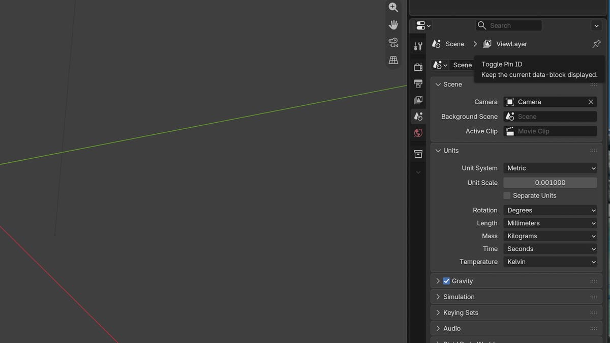
Slicers work in millimeters. A model built in Blender’s default meters can come out the wrong size when you import it.
- In the Properties editor (the panel on the right, below the Outliner), open the Scene tab. The tabs are the column of small icons along its left edge. Scene is the fifth one from the top, an icon of a cone and a sphere, just above the red globe of the World tab.
- Open the Units panel.
- Check that Unit System is set to Metric (it is by default), then set Length to Millimeters.
- Set Unit Scale to 0.001, so that 1 Blender unit equals 1 mm.
Length now reads “mm” everywhere, for example in the Dimensions fields. The grid also changes scale and the fine grid lines can fade out. That is expected.
Save your file as you go, because Blender can only undo a limited number of steps, so a saved file is your way back if something goes wrong. You can do this with File > Save (Ctrl + S, or Cmd + S on a Mac) and give the project a name. Press the shortcut again after each step of the project below.
Navigation
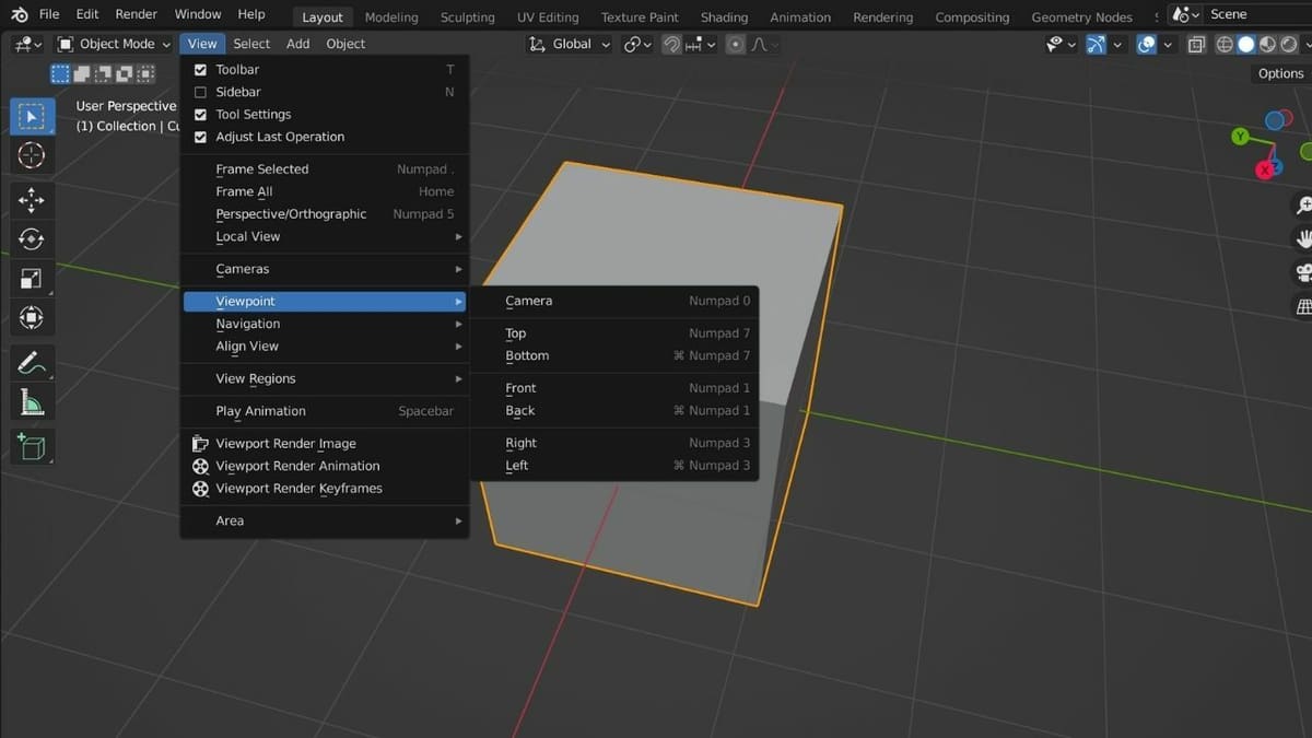
Keep the cube in the scene while you practice. Moving around the 3D Viewport takes three movements: orbit, pan and zoom. Make sure the pointer is over the 3D Viewport first.
To orbit, click the middle mouse button (MMB) and drag. To pan (move the view left, right, up or down), hold Shift and drag with the MMB. To zoom, scroll the mouse wheel.
No middle mouse button? On a trackpad, swipe with two fingers to orbit. Hold Shift and swipe with two fingers to pan. Pinch two fingers together to zoom out and spread them apart to zoom in.
The navigation gizmo in the top right corner works without a mouse wheel too. Drag the axis circles to orbit the view. Below them, drag the magnifier to zoom and the hand to pan. The grid icon switches between perspective and orthographic view.
Click an axis circle (X, Y or Z) on the gizmo to look straight along it. The same views are in the View menu, under Viewpoint: Camera, Top, Bottom, Front, Back, Right and Left.
If you get lost, choose View > Frame All to bring every object back into view, or View > Frame Selected to zoom in on the selected object.
Essential Tools & Operations
Before we start with the tutorial, let’s look at the most important tools and operations that we’ll be working with.
Creating Objects
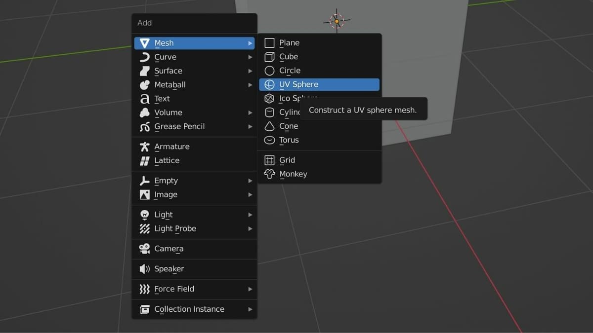
A mesh is all you need to create an object for 3D printing. Move the pointer over the 3D Viewport and press Shift + A, or open the Add menu in the viewport header, and choose Mesh. A list of shapes opens: cube, plane, circle, UV sphere, ico sphere, cylinder, cone, torus and a monkey head. Press Esc to close the menu without adding anything. We add our first shape in the project below.
New objects appear at the 3D cursor, and a small settings panel opens at the bottom left of the viewport right after you add one.
Transformation
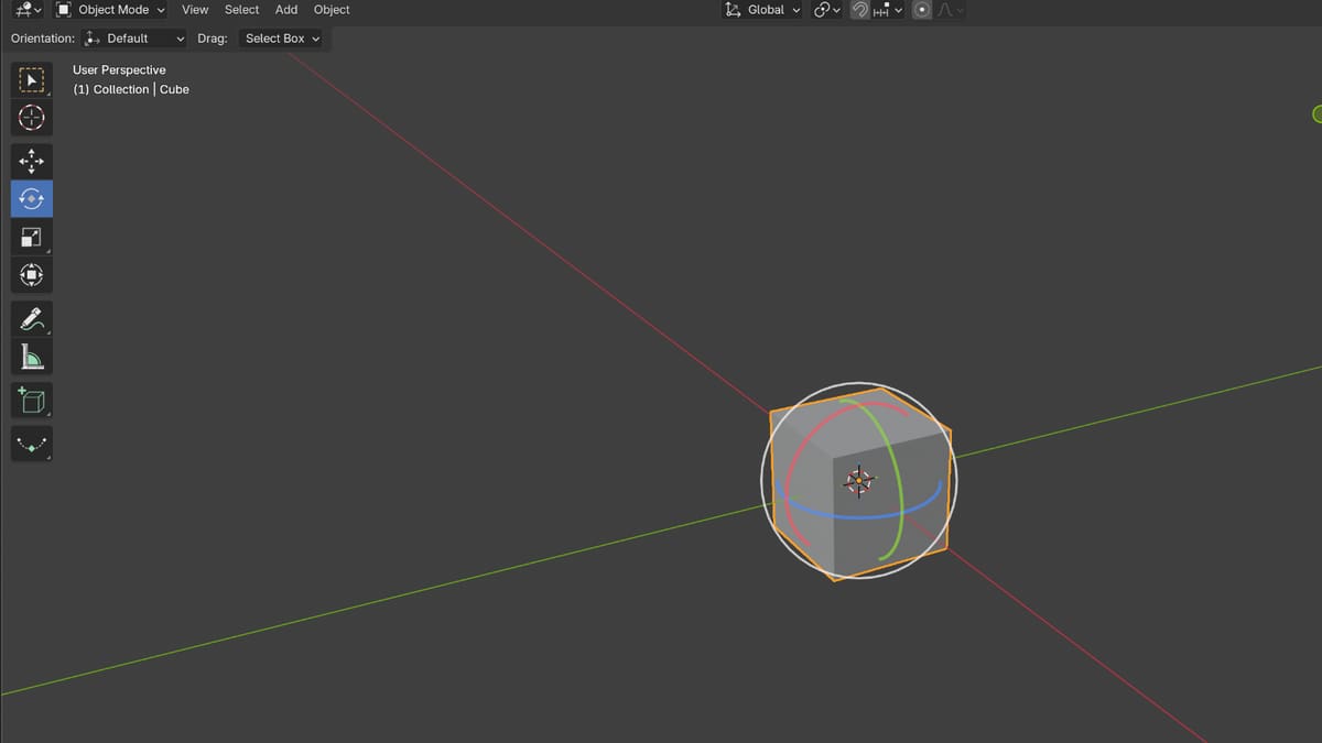
Three operations let you transform an object: move (G), rotate (R) and scale (S). There are two ways to use them, with the keyboard or with the tools in the toolbar. Either way, work in Object Mode and select the object first.
The first way is the keyboard. Move the pointer over the 3D Viewport and press G, R or S, then move the mouse and click to confirm. Press Esc to cancel. To make the object move along one axis only, press X, Y or Z straight after the key (for example, press G and then X, and the object slides left and right along the red X line). To enter an exact value, type a number.
The second way is the toolbar on the left of the 3D Viewport. The transform tools sit below the Select and Cursor tools: Move, Rotate and Scale. The Transform tool, the icon with a small square inside a circle with four arrows, combines all three. Click the object to select it, then pick a tool.
For precise adjustments, move the pointer over the 3D Viewport and press N to open the sidebar. The Item tab shows the object’s Location, Rotation, Scale and Dimensions, and you can type values straight into the fields. With the units set to millimeters, the default cube measures 2 mm on each axis.
The 3D cursor
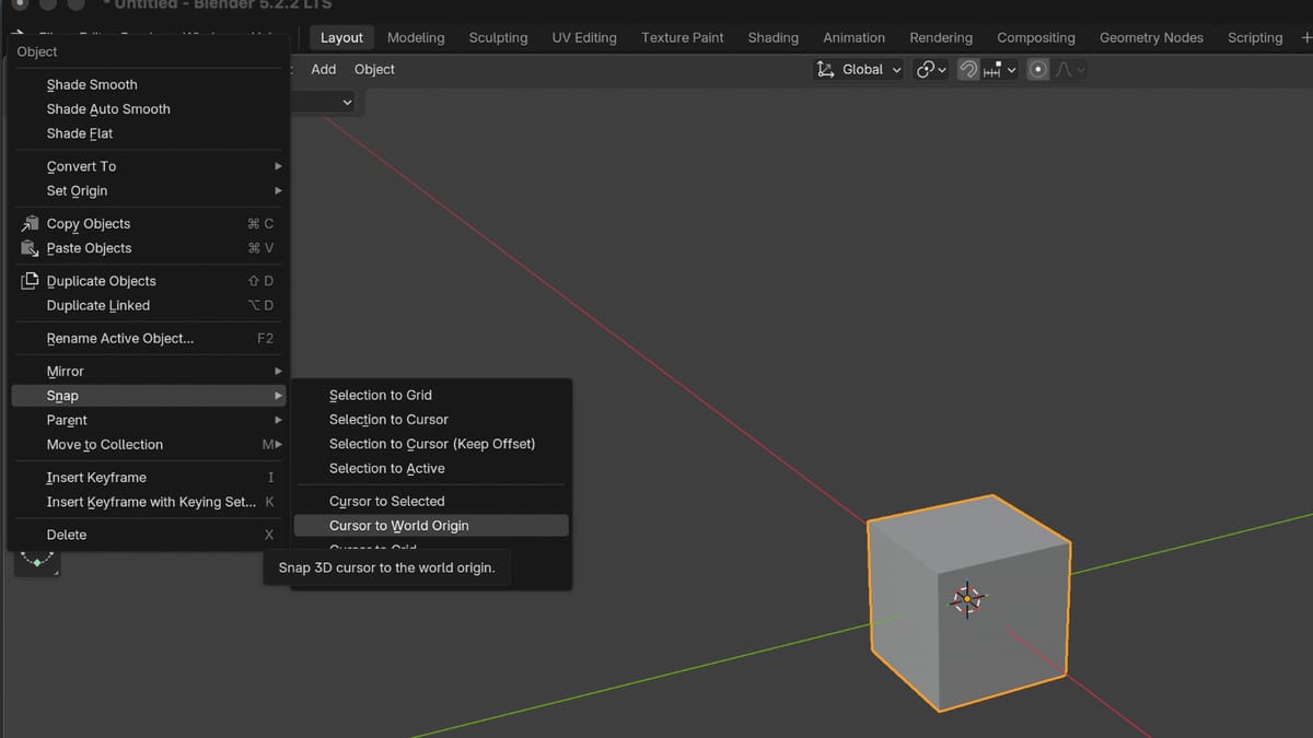
The 3D cursor is the red-and-white circle with a crosshair in the middle of the 3D Viewport. It isn’t an object. It marks where new objects appear. To place it, pick the Cursor tool in the toolbar (the crosshair icon) and left-click anywhere in the 3D Viewport. To send it back to the center of the scene, the world origin, open the Object menu in the header (the last menu, next to Add) and choose Snap > Cursor to World Origin.
Edit Mode
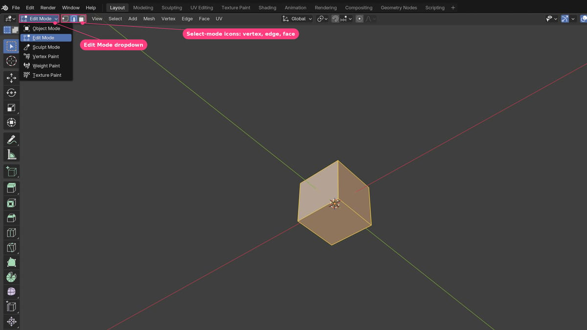
So far you have moved whole objects. To change the shape of a mesh itself, you work in Edit Mode. Hover over the 3D Viewport and press Tab to switch between Object Mode and Edit Mode. In Edit Mode the object shows its vertices (dots), edges (lines) and faces (the surfaces between the lines), and selected parts turn orange.
Next to the mode dropdown in the header are three select-mode icons: vertex, edge and face select. They decide what you pick when you click. Hold Shift and click to add more parts to your selection, and use Select > None or Select > All to clear it or pick everything.
Modifiers
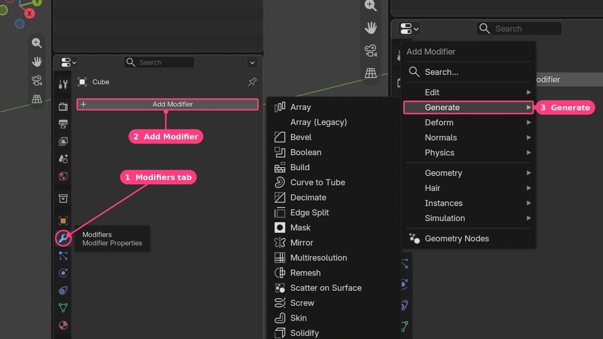
Modifiers are automated functions that change an object’s geometry without touching the original mesh until you apply them. You find them in the Modifiers tab, the wrench icon, in the Properties editor. Click Add Modifier to open a list sorted into categories. We use one modifier in the project below, Subdivision Surface, which smooths a mesh. It is in the Generate category.
Clean Up
You’re done practicing. The default cube is only 2 mm wide, far smaller than the model you are about to build, so delete it: select it, move the pointer over the 3D Viewport and press delete. The Outliner should now show an empty Collection, and the scene is ready for the project.
Jack-O'-Lantern Tutorial
Now that we’ve covered the basics about Blender, let’s get spooky!
Add UV Sphere
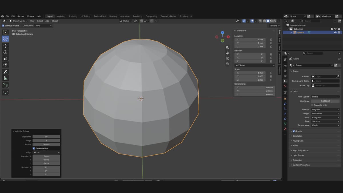
While there are plenty of objects that could be 3D printed all on their own, we want to do something a little more interesting. How about a jack-o’-lantern? Before you add a new object, make sure that you’ve set the unit system to metric and the length to millimeters (mm).
The pumpkin starts as a sphere. New objects appear at the 3D cursor, so first send the cursor back to the center of the scene: open the Object menu in the header and choose Snap > Cursor to World Origin. Then move the pointer over the 3D Viewport, press Shift + A and choose Mesh > UV Sphere. Blender adds new objects at a default size of 1 m, which is far too big here, so set the size right away.
- Open the Add UV Sphere panel at the bottom left of the viewport by clicking its small arrow. Do this right away, because the panel disappears as soon as you click something else.
- Set Segments to 16, Rings to 8 and Radius to 30 mm. Segments are the vertical lines around the sphere, and they decide how many ribs the pumpkin gets later. Rings are the horizontal lines. Fewer lines keep the model light and easy to work on. The radius gives a pumpkin that is 60 mm across.
- Choose View > Frame Selected to zoom in on it.
- To check the size, press N and look at Dimensions in the Item tab. It should read 60 mm.
The panel only stays while adding the sphere is the last thing you did. If you click something else first, such as another object or a setting elsewhere, it disappears. To bring it back, choose Edit > Adjust Last Operation in the menu bar at the top. If that doesn’t bring the panel back, select the sphere, press delete, and add a new one with Shift + A > Mesh > UV Sphere.
Make the Ribs
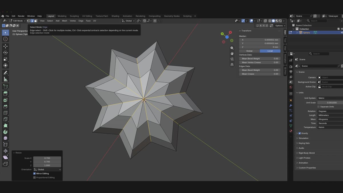
A pumpkin is divided into ribs, the vertical ridges that run from the stalk to the base. You make them by pulling every second vertical line of the sphere inwards, which leaves a groove between the ridges.
- Hover over the 3D Viewport, press Tab to go to Edit Mode, and choose Select > None.
- Next to the Edit Mode dropdown, click the middle of the three select-mode icons (edge select).
- Open View > Viewpoint > Front.
- Hold Alt (Option on a Mac) and click one of the vertical edges, on the line between two dots. The whole line from the top to the bottom of the sphere lights up.
- Hold Shift + Alt (Shift + Option on a Mac) and click every second vertical line around the sphere, skipping one each time. Orbit the view to reach the back. With 16 segments you need 8 clicks.
- To check, open View > Viewpoint > Top. Every second line running out from the middle should be orange.
- Hover over the viewport and press S, then Shift + Z, type 0.7 and press Enter. Shift + Z leaves the up-and-down direction alone, so the selected lines move only inwards.
Smooth it with a Subdivision Surface modifier
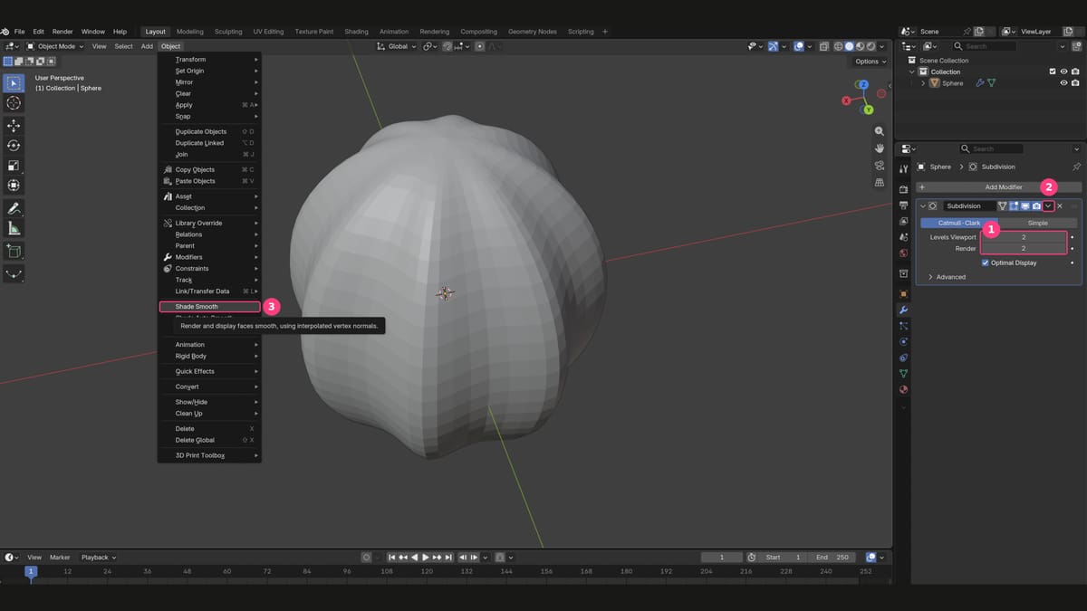
The sphere is still made of flat faces. A Subdivision Surface modifier splits every face into smaller ones and rounds the whole shape, so the ribs become soft curves. Save your file with Ctrl + S (Cmd + S on a Mac) first.
- Hover over the viewport and press Tab to go back to Object Mode. The sphere should have an orange outline.
- Open the Modifiers tab (the wrench icon) in the Properties editor.
- Click Add Modifier and choose Generate > Subdivision Surface. A panel called Subdivision appears.
- Make sure Levels Viewport and Render are both set to 2.
- Apply the modifier. You must be in Object Mode, because Apply is greyed out in Edit Mode (press Tab if you see the black cage of vertices). On the right of the panel’s header, click the small down arrow and choose Apply. Applying turns the smoothing into real geometry, which 3D printing needs. The modifier disappears from the list.
- The shading may still show faint banding. With the pumpkin selected (orange outline), open the Object menu in the header and choose Shade Smooth. This only changes how the surface is shaded, not the shape.
If you can’t see the arrow, the Properties editor is too narrow. Drag the border between it and the 3D Viewport to the left to widen it.
Keep the levels low. Each level splits every face into four, so a high value can make Blender slow or even freeze, especially on an older computer.
A note on symmetry: many modelers work on one half of a model and let Blender’s Mirror modifier copy it to the other side, which keeps a face perfectly symmetrical. That needs extra steps in Edit Mode, so this beginner tutorial skips it and traces the whole face instead.
Squash it
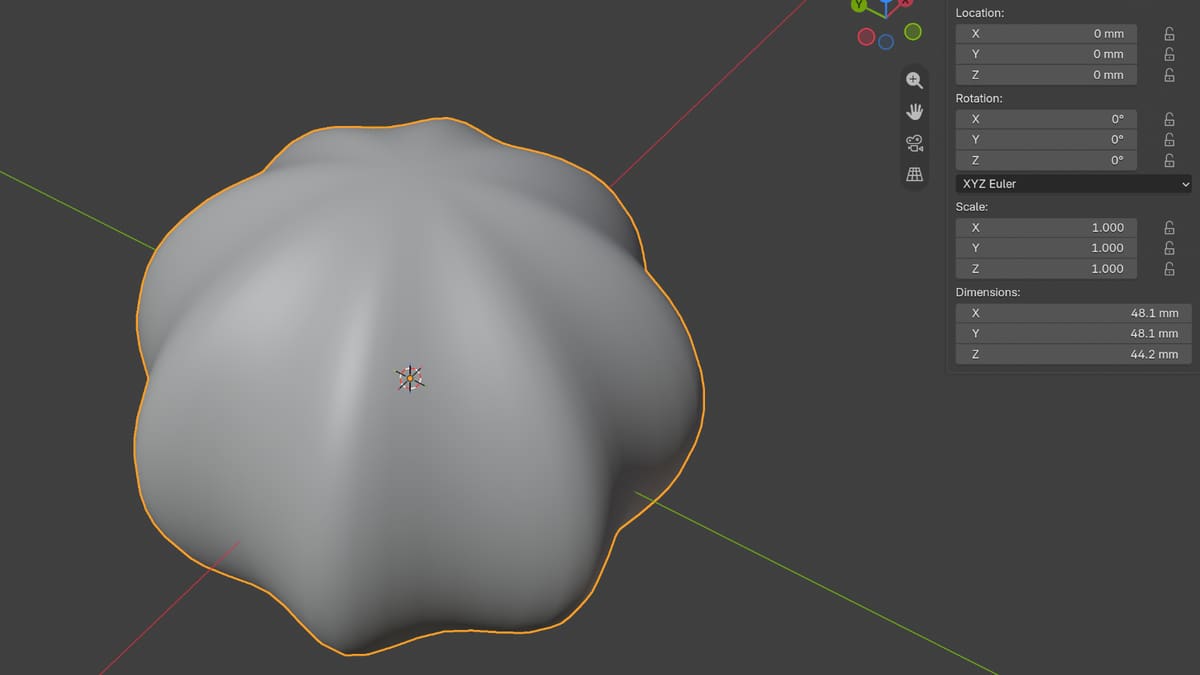
A real pumpkin is wider than it is tall. You squash the mesh in Edit Mode rather than scaling the object, so the object’s Scale stays at 1.000 and the Dimensions are the true size you print.
- Hover over the viewport and press Tab to go to Edit Mode, then press A to select everything (or choose Select > All). Everything turns orange.
- Press S, then Z, type 0.75 and press Enter.
- Press Tab to go back to Object Mode and check Dimensions in the Item tab (N). The height should now be clearly smaller than the width: about 48.1 × 48.1 × 44.2 mm. The width is set by the ridges you didn’t pull in, so it stays the same however deep the grooves are.
Carving the Face
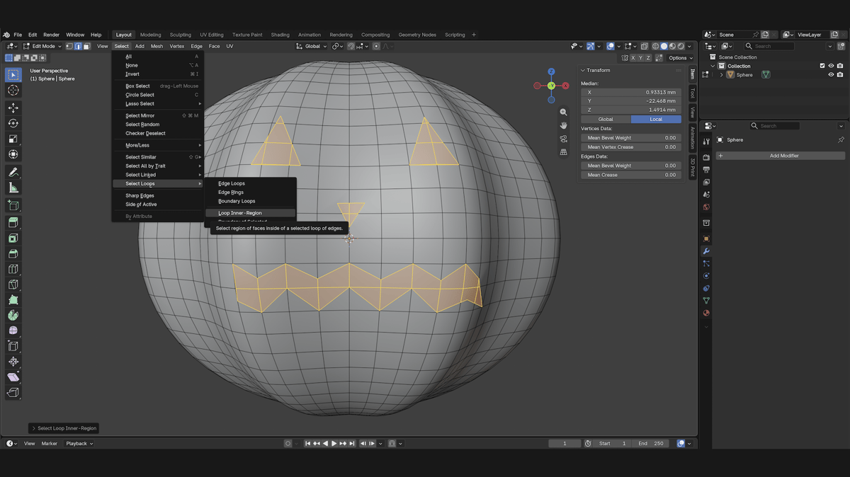
You carve the face one shape at a time, starting with the mouth. For each shape, you cut its outline with the Knife tool, select the area inside and push it into the pumpkin. Then you repeat the same steps for the next shape.
- Hover over the viewport and press Tab to go to Edit Mode, then choose Select > None.
- Open View > Viewpoint > Front and zoom in so the front of the pumpkin fills the viewport.
- Press K. The cursor turns into a small knife. (If a keyframe menu opens instead, you are still in Object Mode. Press Tab first.)
- Click once for each corner of the shape. A line follows the mouse between your clicks. Each click adds a corner, so keep the number of clicks low. Shapes with few corners, such as triangles, are easier to engrave than rounded ones.
- Press Enter to finish the cut. The new edges appear on the surface and stay selected (orange).
- Don’t click anywhere in the viewport yet, because a click replaces the selection. Choose Select > Select Loops > Loop Inner-Region. The faces inside the shape are now selected, and the rest of the pumpkin stays grey.
- Hover over the viewport and press E (Extrude). Move the mouse towards the middle of the sphere. The area sinks in, and the header shows the depth in millimeters.
- Keep the cut shallow, about 2 mm for the mouth and the eyes, and click to confirm.
- Choose Select > None before you move on to the next shape. Then press K and repeat from step 4 for each eye and the nose. If the previous shape is still selected when you start the next one, you can select it by accident and extrude it a second time.
Don’t worry if the wireframe looks messy after a cut. The Knife adds a new point wherever your line crosses an existing edge and joins the points with extra edges, so the cut crosses the sphere’s grid as a zigzag of small triangles. That is normal.
For small shapes such as the nose, use about 1 mm. On a tiny shape with sharp corners, a deeper cut makes the walls cross each other, and the printability check that you will run later flags this as intersecting faces.
If a cut goes wrong, don’t try to repair it. Open Edit > Undo History and click the entry just before the cut, then cut again with fewer clicks. If you clicked somewhere and lost the selection after the cut, press Ctrl + Z (Cmd + Z) until the orange outline of your cut returns. Don’t go back past the cut itself.
Add the stalk
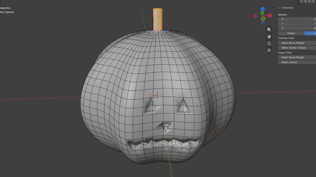
The stalk uses the same cut, select and extrude method, but this time the extrusion goes outwards. Because it grows out of the model itself, it is part of the same solid, which is what a 3D printer needs.
- Stay in Edit Mode and choose Select > None.
- Open View > Viewpoint > Top and zoom in on the middle of the sphere, where all the lines meet.
- Press K, click the four corners of a small square around the middle, and press Enter.
- Without clicking anywhere else, choose Select > Select Loops > Select Loop Inner-Region.
- Press E and move the mouse away from the sphere. Stop when the header reads about 10 mm and click to confirm.
- Open View > Viewpoint > Front to check the result.
The stalk is a plain block. You can make it more interesting later, for example by scaling the top of it smaller, but the block prints fine.
Check the model for printing
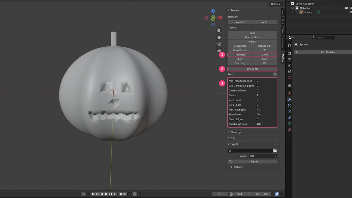
Printers need a closed, “watertight” mesh. The free 3D Print Toolbox extension finds problems before you slice.
- Choose Edit > Preferences > Get Extensions, search for “3D Print Toolbox” and click Install. This needs an internet connection.
- Go back to Object Mode (press Tab) and click the pumpkin so it has an orange outline.
- Hover over the viewport and press N to open the sidebar. Click the 3D Print tab.
- Look at the Thickness setting. The default is 0.001 mm, which is meant for scenes without real units and is far too small for a model in millimeters. Set it to 1 mm.
- Click Check All.
The Result list shows how many faces or edges each check found. For the finished pumpkin, these are the ones that matter:
- Non-manifold Edges and Bad Contiguous Edges should be 0. A value above 0 means the mesh has holes or edges that don’t belong to a closed surface, which slicers handle badly.
- Shells should be 1. It means your model is one connected solid. The stalk counts only because it grows out of the pumpkin.
- Intersect Faces should be 0 or very low. If you see more, a cut was probably too deep on a small shape. Undo it and cut again about 1 mm shallower.
- Thin Faces flags walls thinner than your Thickness setting. On our pumpkin it flags 59 faces, all around the eyes, nose and mouth, because the engraving is only a millimetre or two deep. That is expected here and nothing to fix, because the pumpkin is solid and the engraved walls have material behind them.
- Overhang Faces counts faces that slope more steeply than 45°. A round pumpkin always has many on its underside. This isn’t an error. It tells you the underside may need supports, or that you should split the model.
To see where a problem is, go into Edit Mode and click its row in the Result list. The faces in question light up on the model.
Export as STL
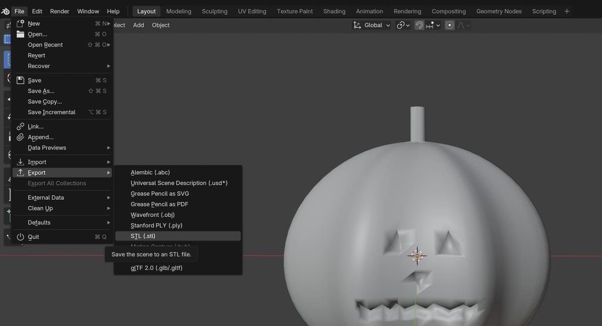
- Click the pumpkin so it is selected (orange outline) and you are in Object Mode.
- Choose File > Export > STL (.stl).
- Enter a file name such as pumpkin.stl, pick a folder and click the export button.
- Open the STL in your slicer and confirm the size and orientation. The pumpkin should be about 48 mm wide.
STL is the standard format, and every slicer reads it. It stores only the shape of the model, with no colors and no units. The slicer assumes millimeters, which is why we set the units at the start.
Give the Face its Own Color in Your Slicer
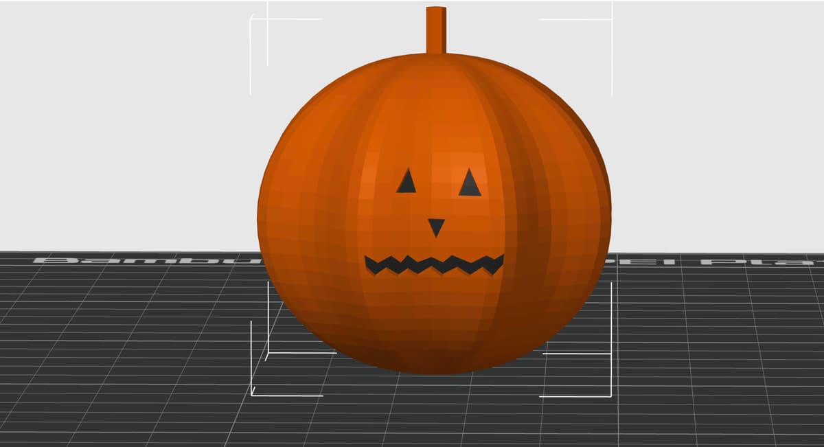
An STL file carries no color, so anything you paint in Blender is lost on export. For a color print, add the color in your slicer instead. In OrcaSlicer, for example:
- Import the STL and select the pumpkin.
- Make sure the project has at least two filaments. Add a second one in the filament list.
- Open the Color Painting tool in the top toolbar and pick the second filament.
- Choose the Fill brush and click inside the mouth, the eyes and the nose. Fill paints a whole connected area with one click, so each engraved shape gets its color. Paint the stalk the same way.
Using AI to Create a Model in Blender
AI LLM’s like Claude or ChatGPT can write a Blender script for you, so you can build a model without learning to code. You describe what you want, the AI writes a short Python script, and you paste it into Blender and run it. Here, we used claude to you will build the same jack-o’-lantern as in the tutorial: a ribbed, squashed pumpkin with a face and a stalk.
A script is code that Blender runs exactly as written. The script below deletes everything in the scene before it starts, so use a new file and save before you run anything. Only run code from a source you trust.
Prepare the Scene
- Choose File > New > General to start a new file. You do not need to change any settings. The script sets the scene to millimeters (Unit Scale 0.001) and removes the default cube, light and camera itself.
Give the AI the Prompt
We asked Claude to write a script that builds the same pumpkin as the tutorial, with the same measurements. Every answer is different, so the script you get may not match ours exactly. Our first version of this prompt had the AI cut the face out with Boolean cuts, which left non-manifold edges and intersecting faces in Blender 5.2.2 (more on that below). We have since changed the prompt, so you should not run into the same problem.
Prompt:
Write a Python script for Blender 5.2 that I can paste into the Text Editor and run. It should build a 3D-printable jack-o'-lantern. First set the scene to metric, millimeters, unit scale 0.001, and delete everything in the scene. Then: (1) make a fine UV sphere (144 rings, 288 segments) with a 26 mm radius; (2) give it 8 ribs by narrowing the sphere to 0.7 of its width in the grooves between them; (3) squash the height to 0.85; (4) press a face into the front (the -Y side): a zigzag mouth, two triangular eyes and a small triangular nose, 2 mm deep (the nose 1 mm), by moving points on the surface inwards, with a short sloped edge around each shape; (5) add a 10 mm tall stalk on top. The result must be one closed, watertight solid with no loose parts. Use the data API and bmesh instead of operators that need the 3D Viewport, and put all sizes at the top of the script as variables.
Run the Script
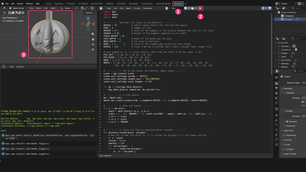
Now you paste the script into Blender and run it. Blender runs scripts in its Scripting workspace, one of the tabs along the top of the window, next to Layout. It has a Text Editor, where you paste the code, and a button that runs it.
- Copy the script from The Script section below.
- Click the Scripting tab at the top of the Blender window.
- In the Text Editor, click New.
- Paste the script with Ctrl + V (Cmd + V).
- Click the Run Script button (the play icon) in the Text Editor header.
- Click the Layout tab to go back, hover over the viewport and press Home to see the whole model.
Check the Result
Press N in the viewport and open the Item tab. The Dimensions should read about 52 × 52 × 54 mm, because the 10 mm stalk adds to the height.
Then run the 3D Print Toolbox check from earlier. Non-manifold Edges and Intersect Faces should be 0 and Shells should be 1. The other counts are much higher than in Step 7, because this model is made of many more, smaller faces. The face is pressed in with sloped edges, so it looks softer than the one you carved by hand.
It Did Not Work the First Time
We did not get this script on the first try. The first version cut the face out with Boolean cuts. It looked right in the viewport, but the 3D Print check found 54 non-manifold edges and 376 intersecting faces around the mouth, so it was not ready to print. The same script made a clean model in an older version of Blender, but not in Blender 5.2.2.
The AI’s fixes did not help. One of them collapsed the pumpkin into a thin sliver. On the last try we changed the prompt so the face is pressed in by moving points instead of being cut with Boolean cuts. That is the script below, and it passed the check. The prompt in this section is the updated one.
A script from an AI is a starting point, not a finished model. The AI cannot see your screen, so check the result every time and tell it what you found.
If Something Goes Wrong
If Blender shows a red error message, take a screenshot and send it to the AI together with the script, and ask it to fix the problem. To go back, press Ctrl + Z (Cmd + Z) or reopen your saved file. If the model works but is not what you wanted, change a number in the settings at the top of the script, such as the squash or the face depth, and click Run Script again. The script clears the scene first, so every run starts fresh. For bigger changes, such as square eyes or a wider mouth, paste the whole script back into the AI and describe what you want.
The Script
This is the version that passed the check.
import bpy
import bmesh
import math

# ---------- Settings (all sizes in millimeters) ----------
RADIUS = 26 # sphere radius before the ribs and the squash
RIBS = 8 # number of ribs
GROOVE = 0.7 # width of the pumpkin in the grooves between the ribs (1 = no ribs)
SQUASH = 0.85 # height of the pumpkin compared to its width
STALK_HEIGHT = 10
FACE_DEPTH = 2 # depth of the mouth and the eyes
NOSE_DEPTH = 1 # the nose is shallower
EDGE = 1.2 # width of the sloped edge around the face shapes
DETAIL = 144 # rings from top to bottom; more rings = sharper face, bigger file

# Face shapes as (x, z) corner points, seen from the front (X to the right, Z up)
EYE_LEFT = [(-12, 5), (-6, 5), (-9, 11)]
EYE_RIGHT = [(6, 5), (12, 5), (9, 11)]
NOSE = [(-2.5, 3), (2.5, 3), (0, -0.5)]
MOUTH = [(-13, -3), (-9, -6), (-5, -3), (-1, -6), (3, -3), (7, -6), (11, -3), (13, -3),
(13, -9), (9, -12), (5, -9), (1, -12), (-3, -9), (-7, -12), (-11, -9), (-13, -9)]

# ---------- 1. Set up the scene: millimeters, empty scene ----------
scene = bpy.context.scene
scene.unit_settings.system = 'METRIC'
scene.unit_settings.length_unit = 'MILLIMETERS'
scene.unit_settings.scale_length = 0.001

for ob in list(bpy.data.objects):
bpy.data.objects.remove(ob, do_unlink=True)

# ---------- 2. A fine sphere ----------
bm = bmesh.new()
bmesh.ops.create_uvsphere(bm, u_segments=DETAIL * 2, v_segments=DETAIL, radius=RADIUS)

# ---------- 3. Ribs and squash ----------
for v in bm.verts:
angle = math.atan2(v.co.y, v.co.x)
scale = 1 - (1 - GROOVE) * (1 + math.cos(RIBS * (angle + math.pi / 2) + math.pi)) / 2
v.co.x *= scale
v.co.y *= scale
v.co.z *= SQUASH


# ---------- 4. Carve the face by pressing points inwards ----------
def distance_inside(point, polygon):
# How far (in mm) the point (x, z) is inside the polygon; 0 or less means outside
x, z = point
inside = False
nearest = 1e9
j = len(polygon) - 1
for i in range(len(polygon)):
xi, zi = polygon[i]
xj, zj = polygon[j]
if (zi > z) != (zj > z) and x < (xj - xi) * (z - zi) / (zj - zi) + xi:
inside = not inside
# distance from the point to the edge between the two corners
dx, dz = xj - xi, zj - zi
t = max(0, min(1, ((x - xi) * dx + (z - zi) * dz) / (dx * dx + dz * dz)))
nearest = min(nearest, math.hypot(x - xi - t * dx, z - zi - t * dz))
j = i
return nearest if inside else -nearest


for polygon, depth in [(MOUTH, FACE_DEPTH), (EYE_LEFT, FACE_DEPTH), (EYE_RIGHT, FACE_DEPTH), (NOSE, NOSE_DEPTH)]:
for v in bm.verts:
if v.co.y < 0:
# points close to the outline are only pressed in part of the way, which gives a sloped edge
d = distance_inside((v.co.x, v.co.z), polygon) + EDGE / 2
v.co.y += depth * max(0, min(1, d / EDGE))

# ---------- 5. Add the stalk: extrude the faces at the top ----------
bm.faces.ensure_lookup_table()
top = [f for f in bm.faces
if f.normal.z > 0.5 and math.hypot(f.calc_center_median().x, f.calc_center_median().y) < 3.5]
extruded = bmesh.ops.extrude_face_region(bm, geom=top)
bmesh.ops.delete(bm, geom=top, context='FACES')
for element in extruded['geom']:
if isinstance(element, bmesh.types.BMVert):
element.co.z += STALK_HEIGHT
bmesh.ops.recalc_face_normals(bm, faces=bm.faces[:])

mesh = bpy.data.meshes.new('Pumpkin')
bm.to_mesh(mesh)
bm.free()
pumpkin = bpy.data.objects.new('Pumpkin', mesh)
bpy.context.scene.collection.objects.link(pumpkin)
bpy.context.view_layer.objects.active = pumpkin
pumpkin.select_set(True)

# Smooth shading, with the carved edges kept crisp
pumpkin.data.shade_smooth()
pumpkin.data.set_sharp_from_angle(angle=math.radians(40))

d = pumpkin.dimensions
print('Done. Size in mm:', round(d.x, 1), round(d.y, 1), round(d.z, 1))How the Jack-O'-Lanterns Came Out
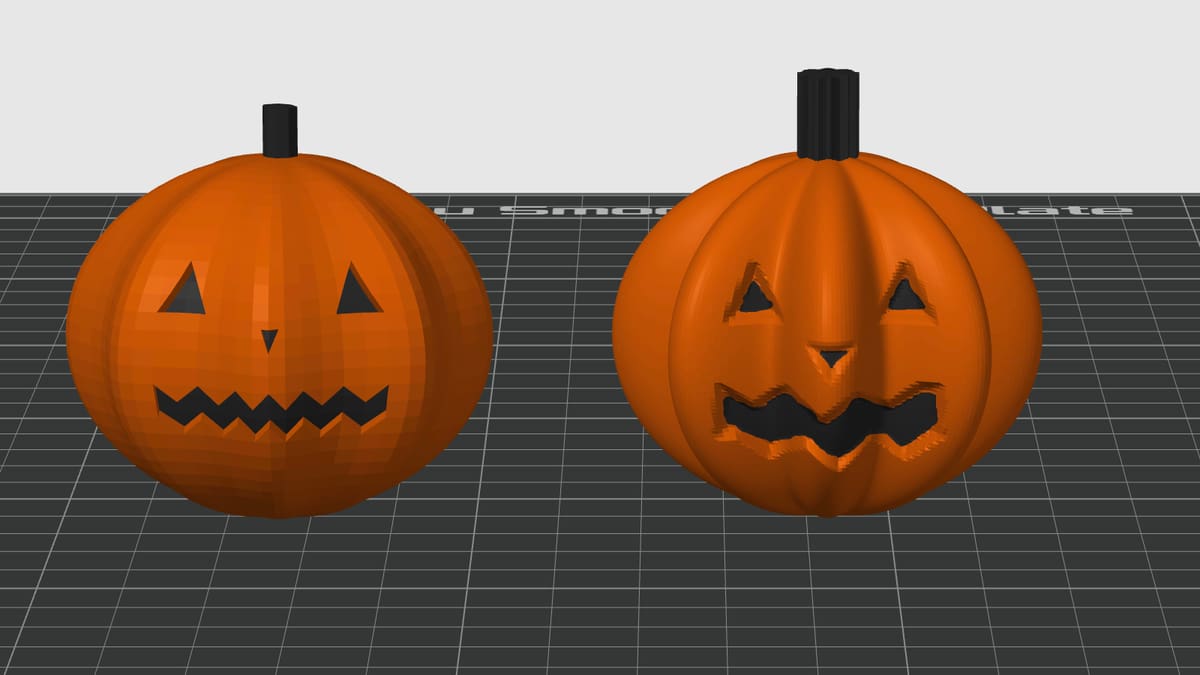
Here are both pumpkins in the slicer: the one we made by hand on the left and the AI-made one on the right. The hand-made pumpkin has sharper, cleaner face cuts but a more faceted body. The AI pumpkin has smoother ribs and a rounder shape, but its face is softer and a bit rough at the edges. Because the AI model is made of so many small faces, the slicer’s fill tool painted most of the pumpkin black instead of just the face, so we had to paint it with the brush tool.
After testing out the two methods, building it by hand takes longer, but you learn how Blender works and you control every detail, including crisp edges on the face. Asking an AI for a script is faster and needs no code, but the result can vary, so be ready to check the model and try again.
Whichever way you choose, run the 3D Print check before you export. A model that looks right in the viewport can still have holes or overlapping faces that a printer cannot handle.
You May Also Like:


License: The text of "Blender Tutorial for Beginners: Make a 3D Printable Model, With & Without AI" by All3DP is licensed under a Creative Commons Attribution 4.0 International License.