
AutoCAD Scale: How to Do It

Scaling is an underrated feature in AutoCAD. Read on to see how to maximize your efficiency using AutoCAD's scale factor.
The Size Is Right
AutoCAD is incredible software that has enabled designers and engineers to achieve wonders in their fields. Invented in the 1980s, the tools it offered were revolutionary in how efficient they made the entire design process. To this day, AutoCAD is the go-to choice for many professionals because of its countless intuitive features. One such tool that we’ll be learning about today is scale in AutoCAD.
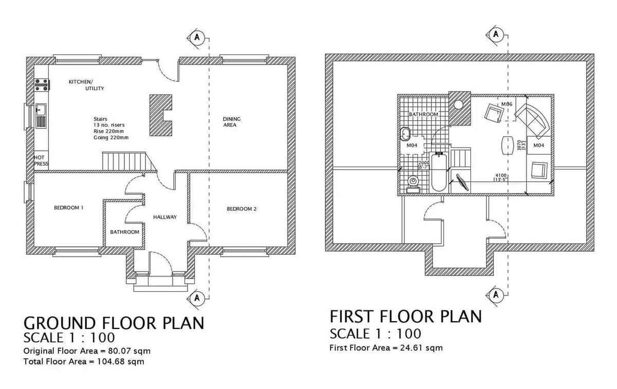
To scale an object or a drawing means to convert it into a more convenient and legible size. Imagine you have a floor plan that measures around 1,000 x 1,000 inches. It doesn’t make sense to print the entire floor plan in its actual size; it’s impractical. So, you can scale it down by a factor of 1:100, which will show on 1 inch of paper 100 inches of the actual floor plan, making it much simpler for representational purposes.
In this article, we’ll be looking into everything that AutoCAD offers with its scaling tool. Let’s get started!

Factoring
The easiest and perhaps most basic feature of the scaling tool is to scale by a factor. You’d use this when you need to scale a drawing to suit your dimensions or you want another copy of a sketch at a different scale.
The scaling factor represents the object’s size as a decimal. A scaling factor between 0 and 1 will scale down an object, and a scaling factor greater than 1 will scale up the size.
Steps
- Select the drawing or the object you want and type the SCALE command.
- Select a base point and add a scaling factor.
- Press Enter and your drawing is scaled. (If you want to keep the original drawing and get another scaled copy of it, use the COPY command for the scale factor.)
Why Use This Method
This tool is easy and straightforward. Instead of having to scale each element at the final stage, you can methodically scale the full drawing whenever you like. This can save time and ensure that other elements in the drawings, such as blocks, hatches (more on these later), and dimensions are scaled accordingly.
Additional Support
You can learn more about the basic scale factor from Autodesk’s official documentation. There’s also a video by College Online that briefly explains the method.
Use a Reference
It’s not always possible to have the exact scaling factor you need for a drawing. This is when scaling objects using a reference is useful. It uses a pre-existing sketch with the same operating principle as the scale factor method: You input the reference length and the desired length, and AutoCAD scales the objects as per the reference.
Steps
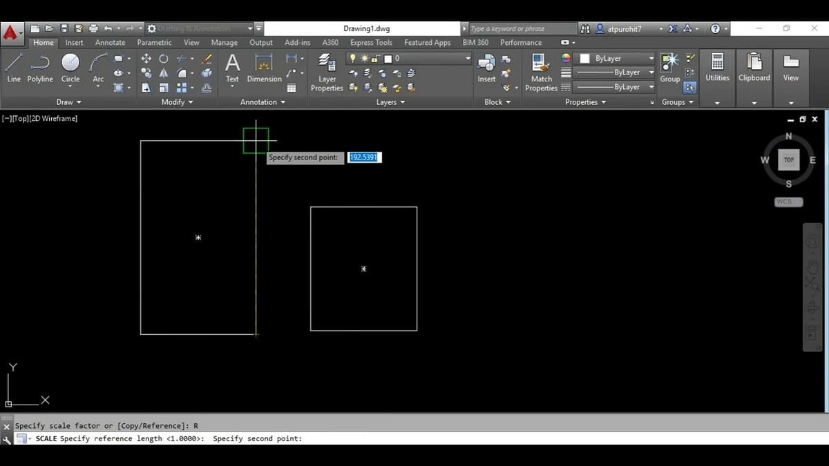
- As an example, draw two squares with sides of 1 inch. One will be our reference square, and we’ll scale the other one.
- Select the reference square and type the SCALE command.
- Select a base point and click the Reference option in the command line.
- Specify the reference length of 1 inch, and then the required length of 1/4 inch.
- Press enter and the square now should be a quarter of its original size.
Why Use This Method
This method is useful when the final scaling factor is unknown. It saves the time required for calculation and also any errors that may arise from using an arbitrary scaling factor. Also, it helps in scaling objects quickly while ensuring that the elements in the drawing are scaled uniformly.
Additional Support
There’s a complete step-by-step tutorial on Autodesk’s website. You can also find a great video by CAD in black on YouTube that explains reference scaling in detail.
Using Imported Images
This scaling technique is useful for scaling images and drawings that you’ve imported into your drawing space.
Consider a drawing in a PDF format you’ve imported that shows a dimension in it that’s 10 inches in length. But, when you measure it in AutoCAD, it shows a different value. If you were to edit it now, the drawing would cause a complete mess. So, to make its dimensions match its stated length, you’d use the scale command. The process is similar to the scale by reference technique.
Steps
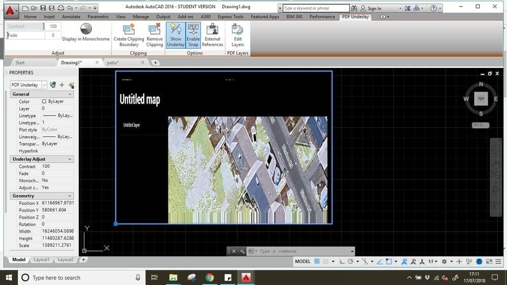
- Import the PDF or image using the import function.
- Select the PDF or image and type SCALE in the command line.
- Select two points on the image or drawing with known dimensions. These will be our reference points.
- Input the value of the specified dimension and press Enter. The dimensions on the image are now scaled to match the dimensions in the drawing.
Why Use This Method
Images and maps are often used by designers as references in their drawings; incremental sketches are drawn over pre-existing drawings, aiming to improve or revise the previous sketch. The issue is that the scale of an image file is not necessarily accurate, depending on where it was exported from and whether it has been resized in the interim. Once an initial scale has been set, the designer can then draw or edit the sketch or floor plan without being worried about deviation from the original plan.
Additional Support
You should definitely check out Autodesk’s documentation, where they explain the steps for scaling an image or a PDF in detail. The CAD in black YouTube channel also has a short but detailed image scaling video tutorial.
Hatching
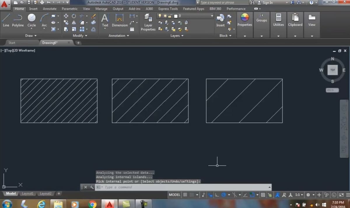
Hatching is a crucial feature of drawings that shows the cutting plane in an object. In architectural drawings, hatching often visually represents the various material types used. In other words, hatching helps the viewer understand different sections in a drawing.
Sometimes, when you use the HATCH command in AutoCAD, you may either get lines that are too close or too far apart. Both of these mean that the hatching lines aren’t to scale in the drawing. This is especially noticeable when you’re printing larger drawings such as homes or buildings.
Let’s understand how you can adjust the hatch size properly.
Steps
- Consider that a length of 100 inches in real life is represented as 10 inches in a sketch. This scaling factor is 0.1.
- Select the area you want to hatch using the HATCH command.
- Calculate the scale factor (in this case 0.1) and enter the value in the Hatch scale factor box.
- Press enter and the hatch scale now matches the drawing scale.
Why Use This Method
As mentioned earlier, hatching patterns are an important aspect of many drawings. If the hatch scale doesn’t match the drawing scale, the overall appearance of the sketch will be off. You could even end up with a solid blob of ink in your final print of the sketch!
Additional Support
Autodesk has explained very simply how to set the scale of the hatch. You should also check out this video guide by John Bordeau on YouTube where he explains how hatching affects drawings in AutoCAD.
Viewport
The viewport feature in AutoCAD is a great way to preview your drawings before you’ve printed them. In a viewport space, you can represent the various sections in your sketch, displaying whatever you want to highlight. For example, it could be the entire drawing from one side or a couple of close-up views.
Remember, in this scaling method, the drawing is scaled with reference to the paper size and not the actual units or dimensions. So, the scale of the drawing depends on the paper size of your choice. The scale in viewports shows as “paper unit : drawing unit”. Therefore, a scale of 1:10 means that 1 inch on paper will represent 10 inches on the drawing.
Let’s look at how you can get started with scaling in viewports.
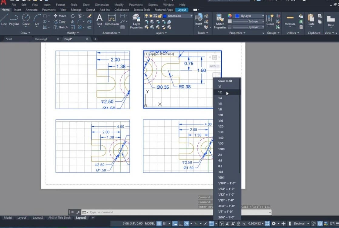
Steps
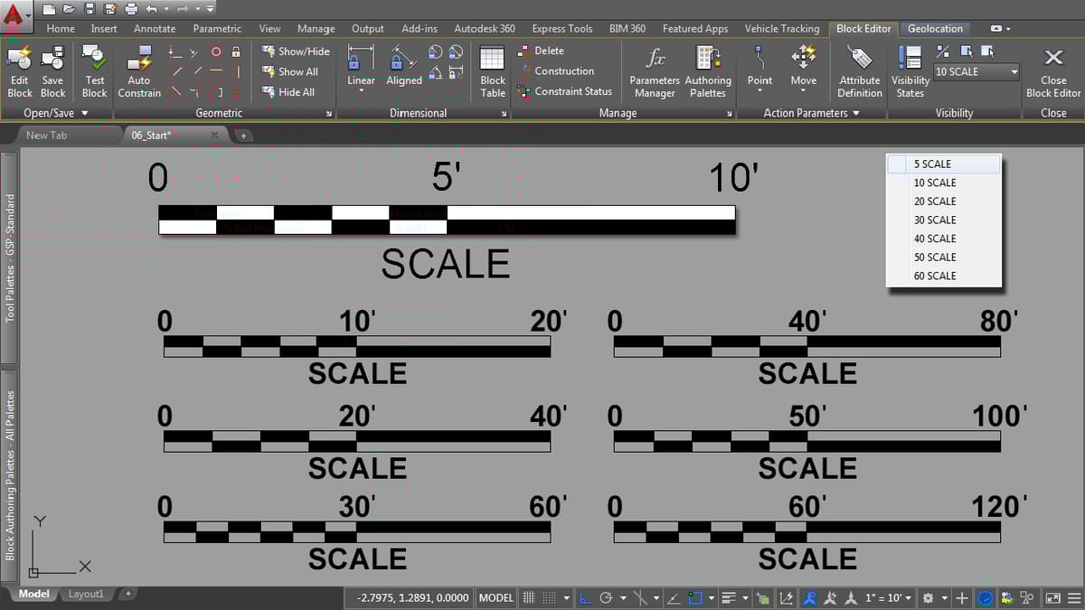
- Enter the layout space and using the “Page Setup” function, set up the page.
- Create viewports using the -VPORT command in the layout space.
- Select any viewport and the scale of the viewport is visible in the status bar below.
- Choose from the available scales to scale your viewport accordingly.
- If the required scale size is not mentioned, select the custom option and add a custom scale.
- Once the viewport is scaled, make sure to lock the viewport to prevent any misalignment.
Why Use This Method
Viewports enable the reader to understand certain areas in the drawing with great detail. When you scale a drawing in the viewport, you can assign multiple scales to one single drawing. Also, as this scaling is being done in the layout space on paper, the dimensions of the original model remain unaffected. This makes it a great choice to obtain one drawing in different scales without affecting the original one.
Additional Support
In AutoCAD’s product documentation, Autodesk has mentioned how you can go about scaling in the viewport. Additionally, there’s a short tutorial by AIMCAD on YouTube that demonstrates how viewport scaling works.
Annotative
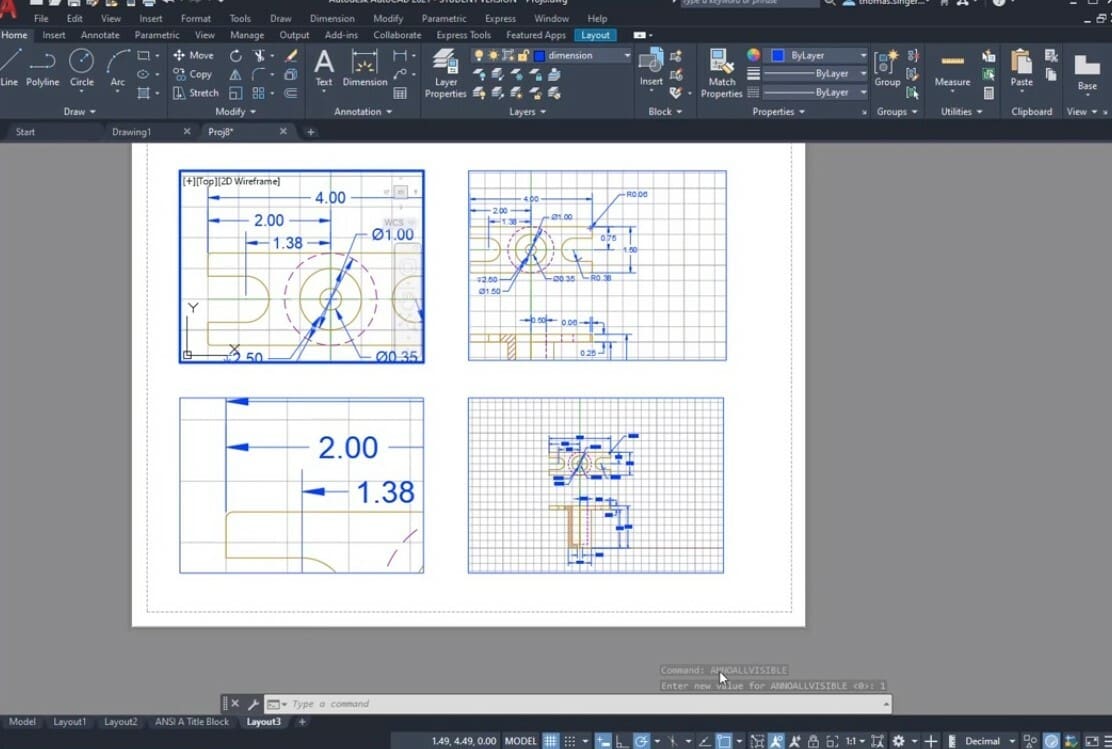
This scaling technique is used to scale annotative objects. (In AutoCAD, you can assign an annotative property to a group of objects.) This ensures that the size of the annotative objects remains the same irrespective of the scale you’ll be using. It comes in handy when you’re printing viewports of your drawing at different scales.
Annotative scaling is commonly used to fix the size of the text and dimensions in a drawing. Let’s consider a case in which you’re viewing a floor plan in the paper space in three different viewports, each with a different scale. One viewport shows the entire floor plan on a 1:2 scale, and two other detailed viewports are scaled as 1:4. If the dimensions and text are not assigned an annotative property, they appear in different sizes on the drawing. Once you make the dimensions and text annotative, no matter which scale you’re viewing you’re drawing in, the text size remains the same throughout.
This method is a bit trickier than the others so we suggest you check out the video linked below. It’ll help you get a clear picture of how to do this and how you can use annotative scaling in your drawings.
Why Use This Method
Annotative scaling offers a great way to make your dimensions consistent across various scales. Earlier, for every new scale, we had to draw a separate dimension or a text. This added a lot of repetitive work. With annotative scaling, once you’ve set the size of the text and dimensions, they remain fixed throughout the drawings as well as adjusting to the scale of the sketch.
Additional Support
Autodesk has provided a short guide on using annotation scaling and objects in their user guide section. Tom Singer on YouTube explains the entire annotative scaling process in detail in his approachable tutorial.
Plotting
Plotting in AutoCAD means printing the output of your drawing. This is the last step in the entire design process. The result is the final output on a sheet of paper that will likely be used as a reference.
When you choose this scaling option, it scales the entire drawing, including all the entities and features. As such, you need to be sure of and keep in mind all the scaling factors you might have used while drawing the sketch. If you’ve used no scale while drawing, this option is handy to do it all at once. Similar to our first method, we assign a scaling factor here. Let’s do it now.
Steps
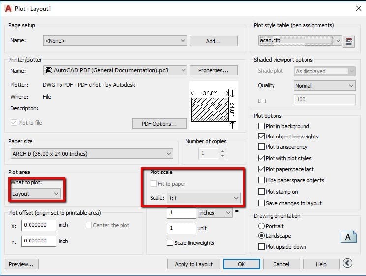
- In the model space, enter “Ctrl + P”. This will open up the print setup window.
- In this window, set up the page and select the printer or plotter of your choice.
- In the plot area, under what to plot, select the window option. Select the two corner points of your drawing. This will be the area that’ll be considered for the final printing.
- In plot scale, set a scale factor from the options mentioned. There’s also a custom scale option available to enter your own values.
- Preview the drawing and hit OK. Your scaled drawing is now sent to the plotter or saved for printing as per your choice.
Why Use This Method
If you haven’t scaled any elements of your drawing and it’s now complete, you can use the plot scale option to do the whole drawing at once: You don’t need to assign a scale to each element individually.
However, keep in mind that elements that are already small may lose all detail (or even disappear!) when scaled down. Also, if you’ve already applied any scales in the viewport or to the actual elements, using plot scale will apply to the existing scale of those objects.
Additional Support
AutoCAD has a short guide that illustrates how to set the plot scale. On the SourceCAD YouTube channel, they explain this method in great detail. The video is suitable for both beginners and experienced designers.
Lead image source: caveman via Wallpaper Cave
License: The text of "AutoCAD Scale: How to Do It" by All3DP is licensed under a Creative Commons Attribution 4.0 International License.