The 3D manufacturing format, or 3MF, is a 3D printing file type that was originally designed to be the new standard for additive manufacturing, although it hasn’t been utilized as much as was hoped. In a nutshell, the main goal of the 3MF is to get software to better “talk” to hardware. In other words, it should improve interoperability between your 3D modeling software, your slicer, and your 3D printer.
The format came about because the most commonly used file type in 3D printing, the STL, isn’t ideal for all of the various printing processes we have today. The 3MF is supposed to be easier to work with for system developers, and it should make the process of going from design to print much smoother. It’s also ideal for printing complex parts that have multiple materials, where there’s a benefit in printing them all at the same time. In short, it’s a step up from STL in many ways.
Let’s take a look at where 3MF came from, why it’s needed, and what it can do.
The History of 3MF
The development of the 3MF has its roots in an open standard called the additive manufacturing file format (AMF). The latter was created as part of an effort by Microsoft to provide support for 3D printing in Windows. Later, Microsoft realized that there were several problems that hindered interoperability. In particular, not a lot of information is carried in an STL – at least beyond the relative X, Y, and Z metrics of the part. For example, the units used during the creation of a part aren’t stored in an STL, so you can’t even be sure of a component’s size when opening an unknown file.
Following talks with leading industry players, the 3MF Consortium was born in 2015. Among others, it originally included companies such as Autodesk, Dassault Systèmes, 3D Systems, EOS, and Stratasys. Since then, the Consortium has only grown.
There are currently 18 “steering” consortium members. These companies are heavily involved in the 3D printing industry, and they engage with the consortium to guide its development. Their main goal is to ensure that 3MF continues to enable 3D design software to effectively and efficiently output all the information required for additive manufacturing.
File Format Properties
The 3MF Consortium tailored the file type for a variety of 3D printers. Toward that end, the core properties of the 3MF are the following:
- Able to store all information: Because a 3MF carries all of the possible information required to make a part – including materials, properties, shapes, and dimensions – results are more consistent. It usually also takes up less disk space than an STL.
- Easy to work with: Based in XML, a well-established markup language, the 3MF is easily usable by a variety of people, developers and engineers included.
- 3D printing specific: Data stored in a 3MF assumes a 3D printing application. This makes it possible to, for example, store print settings (which might not be possible with a generic 3D file format).
- Compatible: Another advantage of XML is that developers can more easily make software compatible with the 3MF.
- Open access: You can see the full specification on the consortium’s GitHub page.
With all of the above in mind, the 3MF is easier to work with from a software development perspective and it carries more information, resulting in a more effective and streamlined process. For example, you can save an entire print bed’s worth of parts and all the related print settings in a single, compact 3MF.
The Purpose of 3MF
There are many file formats for rendering digital objects, including STL, AMF, OBJ, VRML, PLY, ZPR, and ZBD, to name a few. Although they all aim to describe objects in a 3D coordinate system, they’re not all equally suitable for manufacturing objects. Additionally, none of them have the ideal set of features to enable development and communication across different manufacturing-orientated platforms.
As mentioned above, the most common 3D model format for 3D printing is the STL. It was developed by 3D Systems in 1987 alongside the 3D printing technology stereolithography (SLA), hence the acronym STL. At that time, all that SLA printing required of a 3D printing file format was to store the shape of an object. And because SLA was the first 3D printing technology, the STL became the de facto 3D printing file format.
Since then, additive manufacturing has evolved to include a variety of 3D printing technologies. Many bear little resemblance to the SLA of the past, so the STL format isn’t ideal for them. The technological differences, particularly attributes like material types and colors, require a file format that stores more than just a shape.
Furthermore, as 3D printing becomes more widely used, there’s an increasing need for interoperability between hardware and software, where information isn’t ambiguous or lacking fidelity. The 3MF format aims to carry all the information needed to manufacture a part in a single file, regardless of the 3D printing technology used.
Example
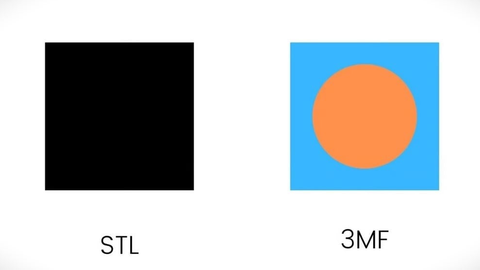
To better understand why 3MF is a step ahead, consider the image above, which shows a single layer of a cube sliced for FDM printing. Running down its center, the cube has a cylinder made of a different material than the rest of the object. In the 3MF cross-section, it appears as orange surrounded by blue. The 3MF can therefore carry that information to your slicer, which automatically knows that there are two materials within the cube. The STL, which is only storing the cube’s shape, doesn’t recognize the two materials.
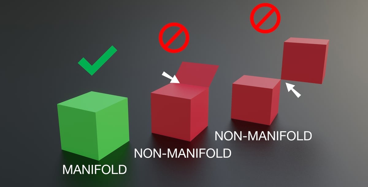
The 3MF might, for example, let your slicer know that the blue material is PLA and the orange material is TPU. From the STL, on the other hand, your slicer only knows that the layer is a square. To reproduce the same result using the STL file format, you would have to combine two STLs, one being a cube with a hole and the other being a cylinder. The 3MF also ensures that your part is manifold and that there are no paths resulting in undesirable movements for the printhead.
From your point of view, it’s just a matter of saving the design as a 3MF instead of as an STL, but it makes a big difference later down the road. You can see the full compatibility list on the 3MF website, but most important is that it’s supported by many slicers, like Cura and PrusaSlicer, and a lot of 3D CAD programs, like SolidWorks.
License: The text of "3MF File Format (3D Printing) – Simply Explained" by All3DP is licensed under a Creative Commons Attribution 4.0 International License.