3D Printer Electrical Wiring: A DIY Guide

When it comes to 3D printer wiring, it's best to get informed! Read on to learn all you need to know about DIY wiring!
DIY plays a massive role in the 3D printing hobby community. You can modify your printer to improve its capabilities and performance, touching all domains, from mechanical to electronic. Unfortunately, safety isn’t a priority for everyone.
With the low and mid-tier printers being offered at affordable prices, oftentimes manufacturers decide to cut down on crucial safety practices. The results are uneventful for the vast majority of users, but for a very small percentage, they can be serious.
In this guide, we’ll focus on good practices and tips regarding electrical wiring, connections, and wire harnessing. We’ll go over the dos and don’ts when modifying your printer’s cabling, as well as some poor manufacturing practices to be on the lookout for.
Whenever possible, we’ll reference the corresponding technical sheet and/or regulations to back up our suggestions. Let’s dig in!

Electrical Basics
In the electronics field, no concepts are more crucial than voltage, current, and resistance. Having a good understanding of how those work together in a basic circuit is crucial for avoiding smoke and sparks. For the sake of brevity, we’ll skip the definitions here, but you can get a great introduction to electricity basics on Sparkfun’s website. We highly suggest checking them out before continuing.
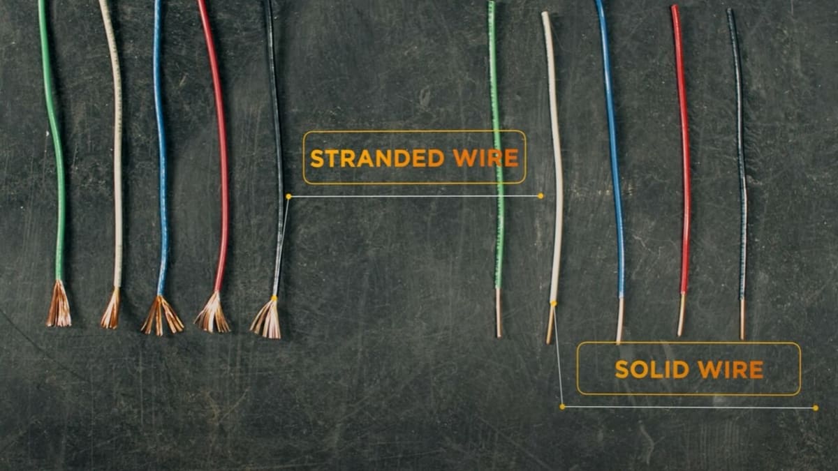
Once the basics are settled, the next step is to explore the different types of wires that can be used in a circuit. Essentially, we can divide them into two categories: stranded and solid core.
Stranded Wire
Stranded wire is the standard type of cabling used in electronics. Its core is made up of several smaller strands, sometimes wound together. This gives it an innate ability to flex, bend, and twist without damaging the core (if done within reasonable limits).
The stands, however, negatively affects the wire’s capacity to carry currents, resulting in a lower current rating compared to same-gauge solid wires. This is mostly due to the air gaps and increased surface area between strands. They also tend to snap when seated in a connector and moved around.
Solid Core Wires
Solid core wires are made out of a single strand of conductive material. This core is significantly thicker when compared to the strands in a stranded wire and can carry more current in a more stable manner, across different ranges of frequencies. Having less exposed surface area, they’re also less prone to corrosion.
Their main disadvantage is flexibility: They cannot bend or twist effortlessly without damage to the core and will snap if subject to repeated stress. They can, however, keep their shape when placed down and are less prone to breakage when inserted in a clamping connector.
Sizing & Materials
Wire dimensions are calculated considering the diameter of the conductor. There are several scales in use for assessing the specs of cable. The most widespread is the American Wire Gauge or AWG for short. This table gives conservative estimates for the maximum current admitted and the voltage drop over a fixed distance. Note that the higher the gauge number, the smaller the core, and the less current can be passed through it.
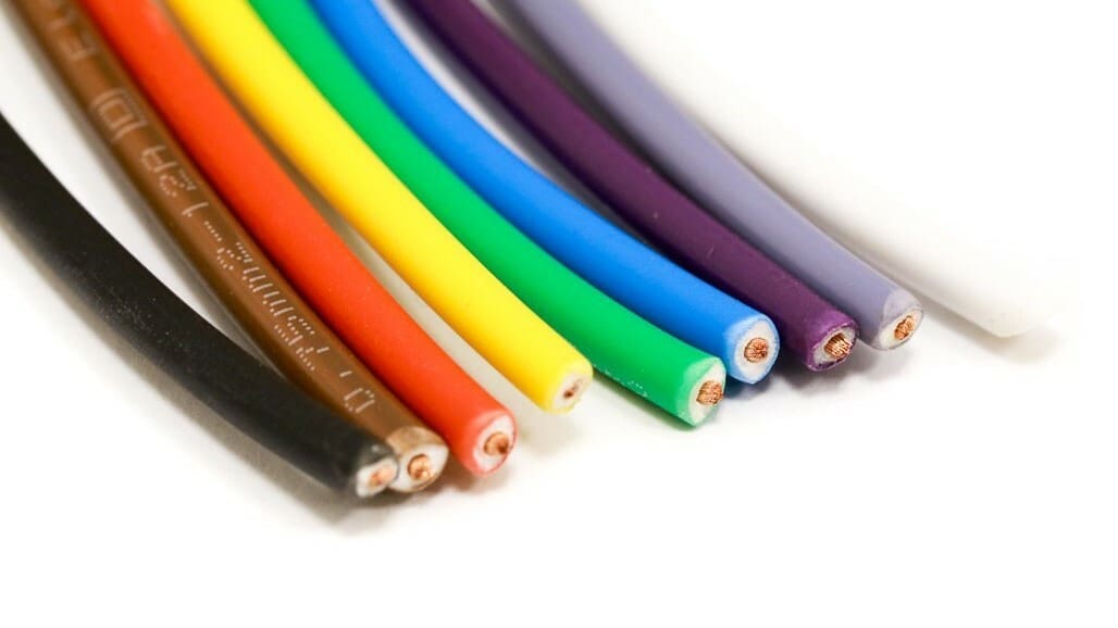
When sizing a wire, it’s also extremely important to consider the materials it’s made out of. For the core, copper or aluminum is used. Copper is preferred, as it has a much lower resistance. Note that sizing charts often show the copper specs, which cannot be used with aluminum cores because the latter are significantly more resistive.
It’s not uncommon to find tinned copper wires, which can be mistaken for aluminum. These wires have the same intrinsic characteristics as bare copper but are also protected from corrosion.
Insulation
For the insulation sheathing, there are many more options to choose from. PVC sheeting covers most of the electronic cables, including the stepper motor, fans, heated bed, screen, and endstop cables. They’re cheap, relatively flexible, and durable for indoor use without exposure to weather. However, not all PVC is made equal: Some extremely cheap cables are more prone to breakage when repeatedly flexed.
Silicone sheathing is also used for power delivery from the power supply to the mainboard, as it’s cheap and highly flexible. This material is also quite easy to cut through and should be carefully installed, especially in metal enclosures. As always, more expensive and better-performing variants are available, but as we’ll see later, wire harnessing plays a huge role in protecting the cables.
There are plenty of other insulation options with different characteristics, use cases, and price points. The two aforementioned options are the default, and regardless of which insulator you choose, we wholeheartedly suggest that you avoid cutting costs on wires.
But what exactly happens if someone ignores all of the above?
Electrical Hazards
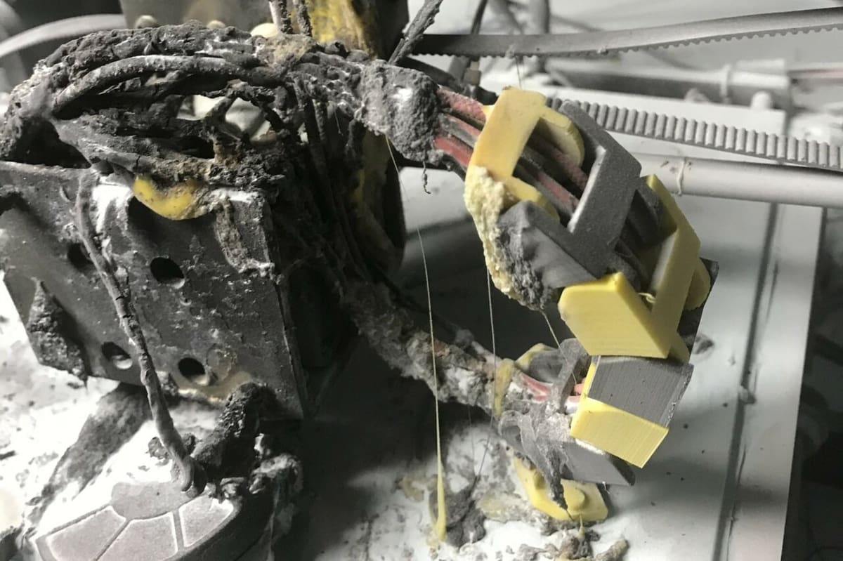
When assessing whether a wiring assembly is in good shape, it’s important to understand what are we looking to avoid. The main offenders in our very specific case include the following:
- Exposed live wires: Especially on the main’s voltage side, there should be no wires with exposed ends.
- Repeated straining: Even if external signs of wear aren’t visible, internal damage might have already occurred. Avoid bending the cable excessively and repeatedly, and consider using cable chains for those that need it.
- Wire tinning: This is the most common cause of melted connectors in 3D printing. To cut costs on terminals, manufacturers strip and tin the end of a wire before inserting it in a clamp terminal. The tin contracts and relaxes with the thermal excursion given by the current passing through. This results in a looser connection over time which means a change in resistance or temperature could lead to the melting of the connector. It’s recommended to cut off the tinned ends and either leave them as they are or use crimp terminals.
- Improper sizing of the wire gauge: As we’ve discussed previously, it’s important to leave some tolerance on the upper end when choosing the dimensions of the cables in order to have a safety margin.
- Poor crimps: Crimped terminals are a great way to improve electrical connections, but an improper crimping technique might result in an even looser contact.
- No cable bundling: Wires need to be bundled together to be protected and routed safely. Flying wires might get caught in the motion system or get tangled with other parts.
Contact Area
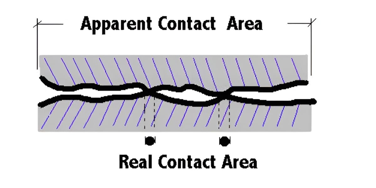
A special mention should be given to contact surface and heat buildup risks. To summarize briefly, in an electrical connector like a USB, HDMI, or barrel jack, the contact surface between the two halves consists of microscopic high and low spots. The high spots are ultimately what allows the current to pass through, by touching each other.
The limited contact area creates a contact resistance, sometimes called “constriction resistance” or “ECR”. This intrinsic characteristic is what decides the current rating for the connector itself.
Poor contact between the mating surfaces (created by corrosion or loose connections) will result in a higher resistance and thermal buildup. Since this excess heat can’t be handled by the connector, it starts melting and in extreme cases, catches fire. Always ensure your connectors are clean, properly seated, and never exceed their current rating.
Finally, remember to power off the printer and unplug it from the wall before working on it. Don’t open the power supply unless you have a very good understanding of where you should (and shouldn’t) put your fingers.
Speaking of fingers, let’s go over the most important safety guard for them: electrical connectors.
Connectors & Terminals
One of the most common questions on 3D printing forums is “What is this connector?”. Luckily for us, 3D printer manufacturers tend to use only a few types of connectors on their boards. Before looking into them, let’s analyze how a connector is assembled.
The main parts are easy to identify. There are two parts to a connector, called the “male” and “female” ends, that enclose the metal pins in a plastic housing. The male half with the metal pins sticking out is sold assembled as-is, while the female one usually has housing without the contacts pre-inserted. It’s up to the user to crimp the cables with the female terminals, then insert them into the housing.
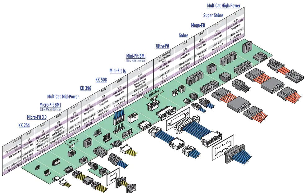
Contacts are rated for a certain current per pin, often associated with a rated wire gauge. Each connector has a defined pitch, which is the distance between the center of each pin. As with cables, always try to leave a bit of leeway on the current rating.
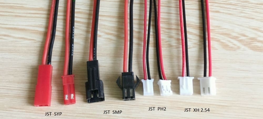
For quick identification purposes, here are the most widespread connectors among 3D printer manufacturers:
- JST XH is widely used for fans, temperature sensors, stepper cables, and endstops. Specs: Wire-to-board, 2.5-mm pitch, max. 3 A, AWG 22.
- JST PH has similar uses to the XH, but with an overall smaller footprint. Specs: wire-to-board, 2.0-mm pitch, max. 2 A, AWG 24.
- Amphenol FCI Mini-PV (DuPont 2.54) is a general-purpose signal connector, used mainly for touch probes and other digital add-ons. It’s the most widespread wire-to-wire and wire-to-board connector, thanks to its low cost and availability. Specs: wire-to-wire and wire-to-board, 2.54-mm pitch, max. 3 A, AWG 32.
- Molex KK 254 is mostly used by older RepRap-style and Duet3D boards for the motor’s connections. Specs: wire-to-board, 2.54-mm pitch, max. 3 A, AWG 22.
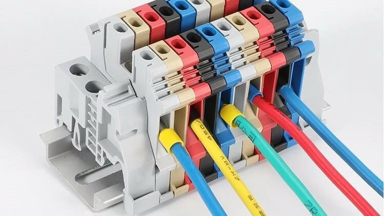
- Terminal blocks are used for the high-current connections, like heating elements and power supply to the board. They’re often non-branded items with no current rating. They work by turning a screw to clamp the wire between two metal plates. Cheaper ones frequently suffer from meltdowns due to improper installations and loose connections. Specs: Wire-to-board, variable pitch, variable current rating.
It’s not rare to find many variants within the same family of connectors. Housings with different shapes and pinouts, purpose-made male connectors, and a wide array of crimp terminals can be all part of the same ecosystem, leading to even further confusion. Each of those has slightly different specs, and it’s important to remember to never mix-match housings and pins. Always consult the datasheet beforehand.
Crimping

Crimping is a key aspect of electrical connections, both industrially and for DIY. It’s a widely adopted way to secure a cable to a terminal, but it’s also one of the most common points of failure.
The principle behind this technique is simple. A metal terminal is clamped to the end of a stripped wire with a pair of special pliers. The copper strands are squeezed together, and their section is deformed to increase the surface contact between them.
Each connector manufacturer has its own set of pliers with specific jaws that follow the shape and dimensions of the crimp terminal. These pliers are calibrated to apply a specific load on the terminal in order to form a consistent and perfect crimp every time.
Matt Millman has created an awesome repository to document and test different sets. We recommend checking it out, even just for curiosity.
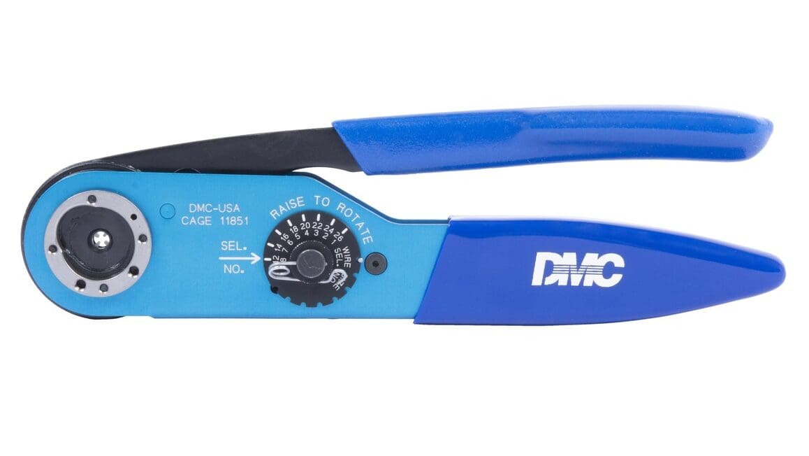
Unfortunately, with great precision comes also a great price tag. Original crimping sets are prohibitively expensive for the average hobbyist, especially if every connector or family of products requires a separate plier.
The solution to this cost issue has been to purchase cheaper knock-off terminals and pliers with interchangeable jaws. These sets aren’t subjected to any quality or validation test and don’t offer a reliable and consistent crimp. They’re often sold at Amazon and AliExpress for $15 to $40 alongside a box of connectors.
The cheaper options often perform well enough for low-current applications, like data transmission, fans, sensors, endstops, and so on. For more demanding applications, however, the lack of reliability isn’t acceptable, especially in the case of connections with a higher current pass-through.
This is applicable to both the plier and the terminals. The materials and tolerances of the cheap kits won’t meet the specifications of the original. A clone of a connector rated for 3 A shouldn’t be considered able to perform equally well. Key factors that contribute to this include low-quality materials, surface finish, as well as wider mechanical tolerances.
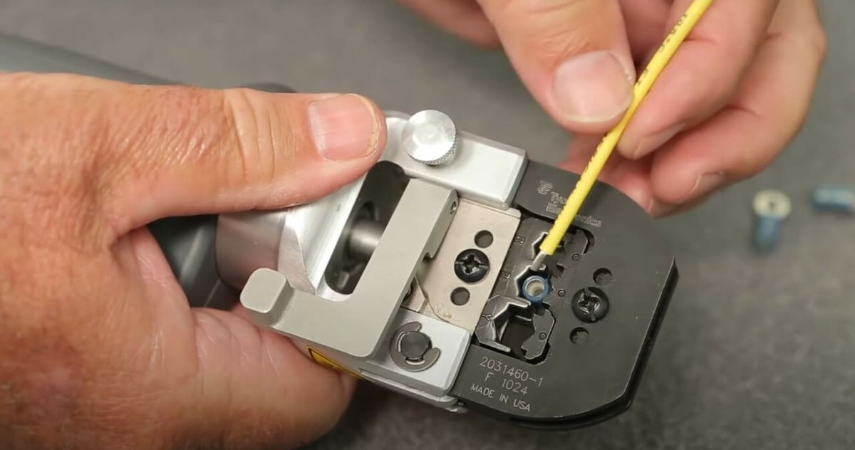
But how do you actually crimp a wire? First and foremost, with a pair of crimping pliers.
Ordinary pliers, cutters, scissors, and hammers are not suited for this job. Strip the end of the wire to allow the copper to be crimped in the terminal. The copper should extend only for the section needed, without being too long or too short. If the terminal is intended to grip on the wire’s insulation too, make sure that it can do so.
- Then, select an appropriate plier and insert the crimp terminal in the jaws that suit the chosen wire gauge.
- Press lightly to fix the terminal in place without closing it.
- Insert the bare wire, then squeeze the pliers firmly.
A proper crimp should never come off the wire. Gently but firmly pull the terminal to check. It’s practically impossible to verify if you have effectively deformed the bunch of strands, as you would need to section the connectors to check. This is the main reason behind purpose-built pliers: a guarantee for a good crimp, every time.
A diagram illustrating a proper crimp is available at Waytek Wire.
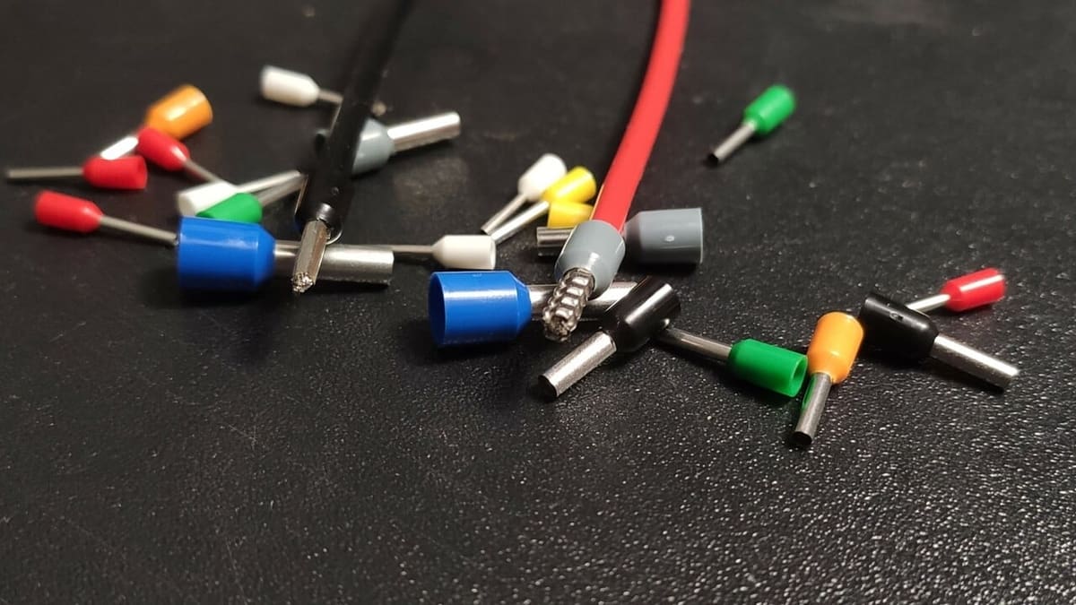
Ferrules
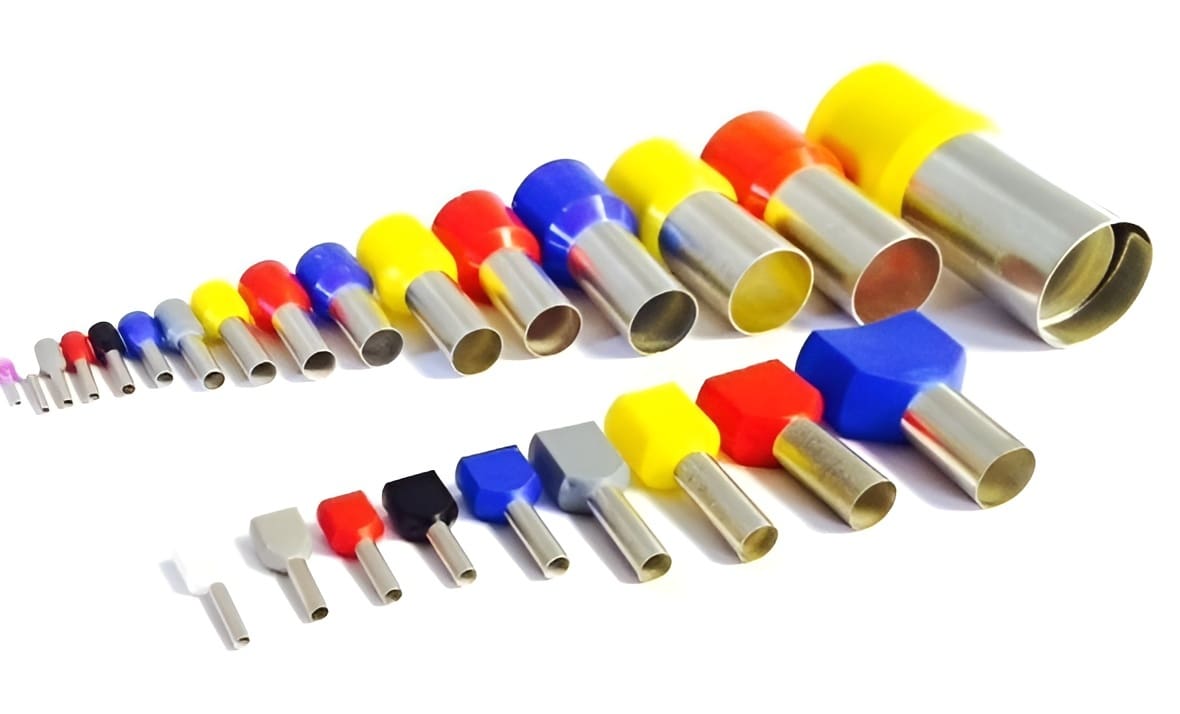
This specific type of crimp terminal deserves a separate section, as it’s often misunderstood and misapplied. Ferrules are tubular crimps used to secure the strands of copper before inserting the end in a terminal. They come in different sections for different wire gauges and are often used with particular pliers that have iris-like jaws.
Contrary to what some users report, ferrules aren’t prohibited for industrial and professional use. Several regulations mention or even mandate the use of ferrules in electrical panels block terminals that aren’t suited for stranded wires. British Standard BS 7671-526.9, the guidelines for the United States under 29.3.6 in UL 508A, and several EU codes like the LVD Standard cover the use of ferrules for both domestic and industrial use.
The concept behind ferrules is to prevent the single strands of copper from breaking loose and making contact with neighboring connectors. The crimp bundles together the cores and prevents shear stresses. This is particularly true for those types of bi-state connectors that aren’t designed to hold stranded wires, such as the very popular Wago terminals. In that case, using a ferrule is necessary.
A problem arises when ferrules are used in terminal blocks designed to hold bare wires. To understand why this scenario is undesirable, we have to look at how they’re crimped.
The iris-like pliers are designed to squeeze the terminal in a shape that resembles a circle. The jaws ideally have six or eight sides to better approximate a circumference. Four-jawed pliers should be avoided, as they push the strands in the four corners of the formed square, reducing surface contact.
In the case of 3D printers, the block terminals are designed to work with bare copper ends. Pressing a circle-like shape between two metal plates reduces the surface contact between the two, resulting in a worse current transfer. This is mostly because the screw terminals don’t have the strength to squeeze the ferrule.
On online forums and exchanges, however, ferrules are often regarded as “fire-prevention” devices and are widely suggested to newcomers. The reasoning behind it is somewhat understandable: Tinned ends are dangerous, and bare copper might shear or come loose over time.
There’s a solution that accommodates both sides of the argument but is often not mentioned. Instead of using bare copper or round ferrules, there’s the possibility to buy pliers that crimp in a shape with two wide flat sides. This is ideal for contact surfaces in terminal blocks and can also protect the wire from snapping off.
As with other crimp terminals, ferrules are not the place to cut corners. Buying quality products from trusted resellers such as RS Components or DigiKey should be always preferred over unbranded Amazon sets.
Harnessing
As we’ve previously mentioned, repeatedly moved cables should be secured and protected. Wire harnessing not only organizes the cables but also prevents them from being caught in the motion assembly. Of course, we still need to allow some of them to move freely. The bed and print head wires shouldn’t be constrained, for example.
To achieve this, there are essentially two aids: cable chains and cable sleeves.
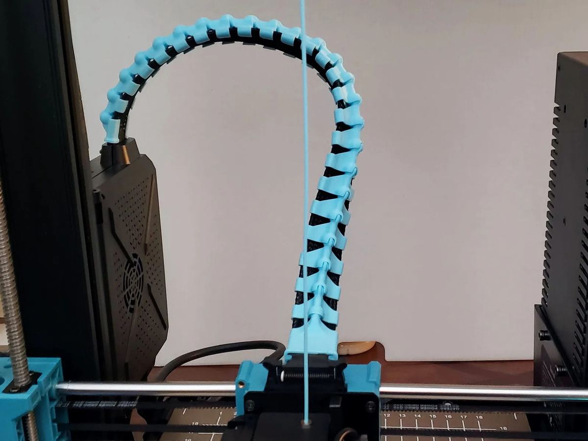
Cable Chains
Cable chains are perfect for those cables that need to move freely. They gently bend the cable over a wider radius while also supporting its weight. They offer only one degree of freedom, so one for each axis would be needed. They come in different shapes and sizes to save space and can even be fully 3D printed.
Cable Sleeves
Cable sleeves are braided and expandable to fit different gauges and bundles. They’re often made of nylon and can be found online as well as in hardware stores. Sleeves are geared to protection: the extra layer prevents pinches and cuts but cannot really sustain the weight of the wires or bend safely.
Their primary purpose is to bundle and route cables from the electronics enclosures of the printer. These boxes are often made of sheet metal with sharp edges and very small openings. A sleeve helps guide and protect the wires.
Most users choose to create separate sleeves for each bunch of wires: one for all the hot end electronics, one for the extruder, as well as separate ones for the filament sensor, X-axis motor, and so on.
Cable Management
Cable management in tight spaces can be a headache, but it’s a one-time task that saves time in the long run. In this sense, separating wires based on destination helps with future-proofing. Motors get divided from temperature sensors, fans are distinguished from heaters, and sensitive digital signals (like a touch sensor) are routed away from noisy cables (like the heaters and power supply output).
When bundling cables, it’s crucial to avoid bending them excessively. Right-angle curves should be progressive and not squared, U-turns should be avoided completely, and wires coming out of connectors should also have the space to bend gently.
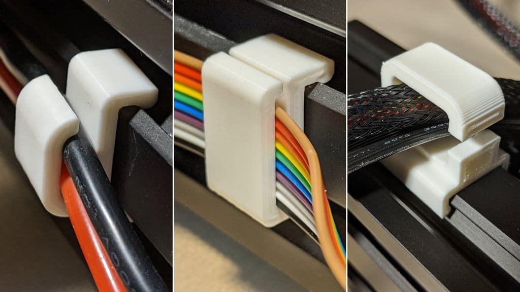
For this last point, in particular, cable ties play a huge role. The temptation is always to tie everything together with single-use plastic. While this is not ideal in the long run (reusable ties are more suited in our case), it’s also important to keep in mind where they’re placed.
For connectors with several pins arranged in a row, it’s important to bundle cables together at least 4-5 cm from the housing. This allows the wires on the extremities to bend gently and not abruptly. Pinching cables to the frame should also be done in a way that doesn’t bend or stress the cores, especially if they need to be moved.

License: The text of "3D Printer Electrical Wiring: A DIY Guide" by All3DP is licensed under a Creative Commons Attribution 4.0 International License.