3D Printer Axis: The Basics Simply Explained

A 3D printer must move in three-dimensional space to create 3D objects. Read on to learn all about how 3D printer axis systems work.
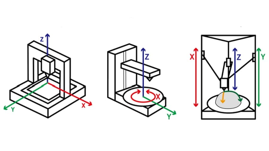
Let’s start with the basics of three-dimensional space: Using a Cartesian coordinate system, any point in space can be located and described using three coordinates respectively lying along the X-, Y-, and Z-axes, each of which is perpendicular to the other two. While one single axis can successfully indicate a position along a line, with three axes, we can situate any point in three-dimensional space.
Although Cartesian coordinates aren’t always used, every FDM 3D printer requires some way to describe positions in space in order to position and locate the nozzle. To accomplish this, meanwhile, different types of machines use different mechanical movement systems to maneuver the hot end and deposit melted filament. The layer-by-layer deposition process is highly dependent on the axes’ movement, which has a direct influence on prints, including quality and speed.
Typically, lateral movement (i.e. left, right, front, back) is usually assigned to the X- and Y-axes, while the Z-axis corresponds to vertical motion. By this convention, each layer is deposited within the XY-plane, while Z movement is responsible for advancement between layers using a pre-defined height set in a 3D slicer.
In this article, we’ll be covering several aspects of FDM 3D printing movement, especially as they pertain to different kinematic systems and movement along axes. We’ll begin by reviewing the different types of 3D printers and how they work.
Types of 3D Printers
An FDM 3D printer can assume a multitude of configurations to enact the three-dimensional movement of its nozzle relative to its build platform. However, there’s no official classification system, which can lead to confusion when discussing various printer styles.
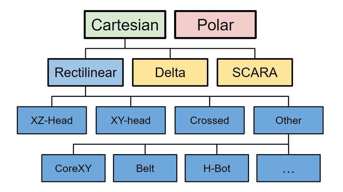
To make our journey into 3D printer movement systems and axes smoother, we’ll use the hierarchy shown in the picture above, which is based on printer coordinate systems and mechanical designs.
Cartesian vs. Polar 3D Printers
The first significant difference among 3D printing configurations is the coordinate system used to reference three-dimensional space.
The common XYZ system is known as the Cartesian coordinate system, named after mathematician René Descartes. As alluded to above, 3D printers using Cartesian coordinates determine the position of the nozzle using three linear coordinates falling along the X-, Y-, and Z-axes. The printhead and build platform are therefore moved around by different rails and driving systems.
Yet, some 3D printers don’t rely on the Cartesian coordinate system at all for positioning. This is the case for polar 3D printers, which is a two-dimensional coordinate system using one linear dimension, radius from origin, and one angular dimension, angle from 0°. (Like Cartesian printers, the third dimension – height – is accomplished by simply raising the nozzle.)
Polar 3D printers can be of different mechanical designs, and in some cases, both the hot end and circular plate can spin around for XY positioning. Still, polar machines are rarely seen in commercial desktop 3D printers, but they can still work quite well.
The second significant difference lies in mechanical design. In this article, we’ll focus on how Cartesian 3D printers function in terms of movement and the components that make their motion systems, starting with rectilinear printers.
Rectilinear
Rectilinear printers are the most common FDM printers and encompass a number of generic and specific subtypes of machines. In the above classification system, “rectilinear” refers to the fact that movement along each axis is (mostly) independent and linear, which typically results in a square- or box-shaped printer design.
Unfortunately, it’s with rectilinear printers that confusion tends to set in. This is due to the fact that many names and labels have emerged over the years, with some having multiple meanings and others overlapping in meaning. For example, one of the major sources of confusion lies in the term “Cartesian”, which is often used not to differentiate from polar printers but to loosely refer to rectilinear printers in lieu of more specific subtype names (e.g. XZ-head). Because this can be misleading, it’s best to avoid labeling machines as “Cartesian printers”, as the vast majority of printers anyway use Cartesian coordinates (including delta and SCARA printers, which aren’t rectilinear).
With this in mind, the following three sections will discuss various types of rectilinear printers, starting with some generic types – XZ-head, XY-head, and crossed – before moving on to some more specific types – CoreXY, H-bot, and belt.
XZ-Head, XY-Head, & Crossed
Most rectilinear printers are either XZ-head, XY-head, or crossed-style printers, where these labels refer to the different gantry configurations.
The moving components for these printers can be pretty heavy, which means that sudden changes in direction at higher speeds can be a problem. This issue relates to the printer’s jerk settings and can lead to inaccurate deposition and even print failures.
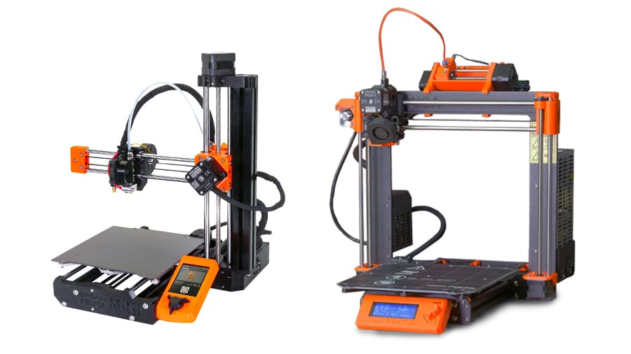
Nevertheless, these 3D printers have the simplest movement systems of all and are often used in DIY 3D printer projects. Note that cantilever-style printers, like the Prusa Mini+ and the Ender 2 Pro are essentially XZ-head printers with a different frame.
CoreXY & H-Bot
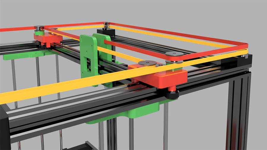
CoreXY 3D printers use a quite special movement mechanism. Their XY lateral movement is driven by two motors and two long timing belts in a rather complicated and dynamic system. Vertical movement (Z-axis) is performed entirely by the build plate in a downward direction.
While these 3D printers have numerous advantages over others, perhaps the most valued is their ability to handle printing at much higher speeds. CoreXY-style printers have fewer and lighter moving parts, which enables faster hot end movement and therefore printing. Contributing to this is the fact that the motors responsible for the XY movement are stationary and attached to the printer’s frame, reducing the vibration significantly.
However, relying too much on long timing belts can be an issue because they must always be properly aligned and tensioned. Low-tensioned belts can lead to inaccurate movements while overly-tensioned belts will increase wear and tear. Low-quality belts can also be a major source of issues in this type of printer.
H-bot 3D printers are very similar in style and often mixed up with CoreXYs, although they differ in the way their belts are configured. While CoreXY uses two timing belts, H-bot style printers use only one, leading to some differences in vibration and torque. Since the tension of this one belt is so important, it requires continual tuning. Furthermore, the specific configuration of the belt has been shown to encourage a non-ideal tug-of-war-style twisting in printhead movement. For these reasons, H-bots have dropped in popularity since their initial appearance.
Belt 3D Printers
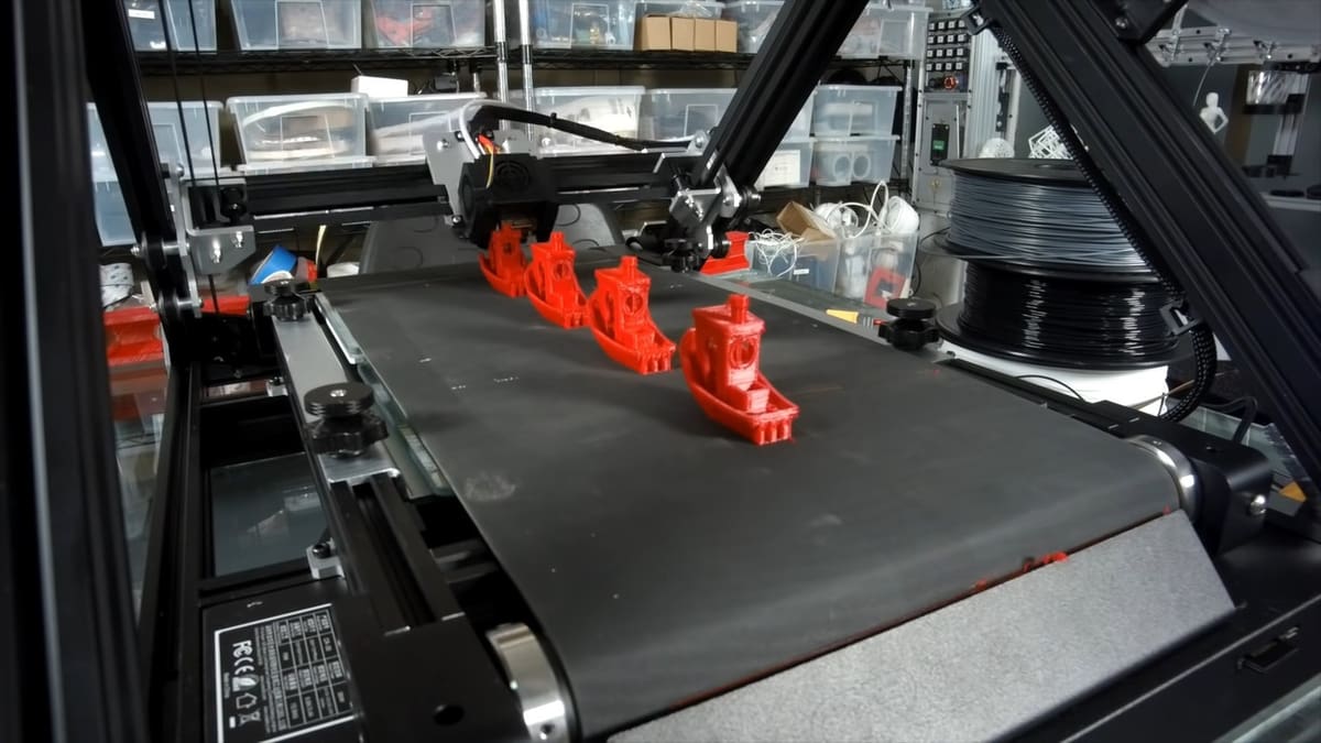
Belt 3D printers are a recent and quite unique addition to the FDM 3D printing world. The “belt” refers to the fact that the build platform is a conveyor belt. This is probably the main selling point of these machines, as it allows users to either create very long parts or repetitively produce parts without ever needing to stop the printer (in theory).
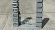
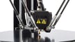
In most cases, belt 3D printers are either a CoreXY or an XY-head printer with a frame that’s tilted relative to the (belt) build platform, meaning that the coordinate system is effectively tilted. For this reason, belt printers are said to have an “infinite” Z-axis. Consequences of this are that overall print speed is reduced and prints may require additional support structures (as seen in the red 3D Benchys above).
These printers also are limited in terms of materials they can use because they lack print bed heating; materials such as ABS can have serious bed adhesion problems.
Delta 3D Printers
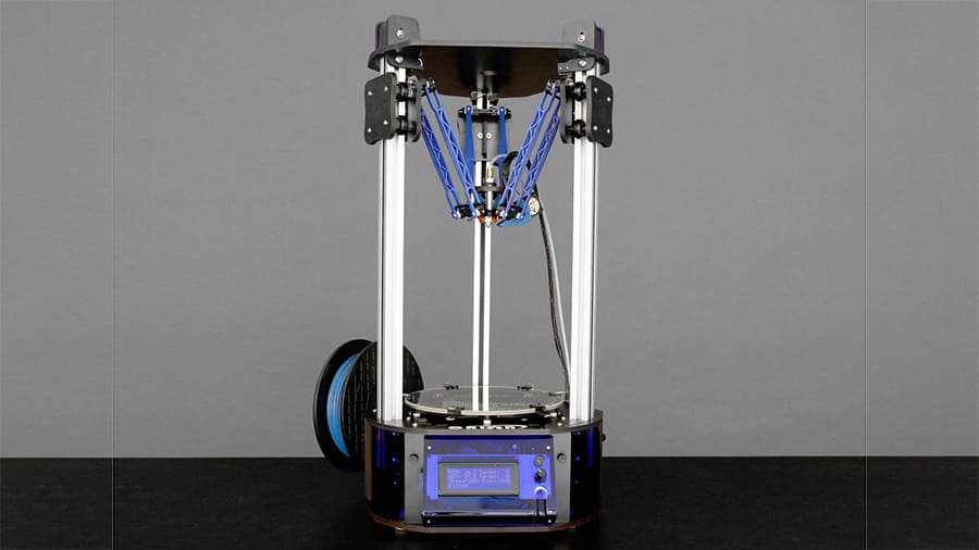
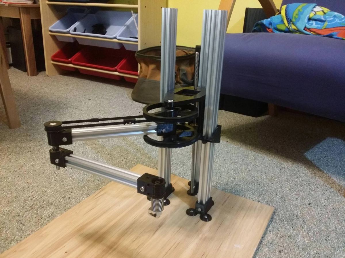
Moving on from rectilinear printers, delta 3D printers employ a rather unique mechanism for movement, known in the industry as a “delta robot”. The hot end in these machines is attached to three moving arms, each connected to its own vertical rail. None of the arms correspond to any individual axis since all hot end movement is performed by all three arms simultaneously.
While still considered a Cartesian printer, the kinematics of delta printers are not as intuitive when compared to rectilinear types. The nature of the movement in delta printers makes for very quick and precise maneuvers since the printhead can be much lighter than on rectilinear machines. This reduces the inertia of the printhead movement, allowing for faster movement and fewer vibrations.
Delta printers have completely stationary circular build plates, which work well when printing circular models. Moreover, their unique design favors height and is usually employed when printing taller objects. At the same time, the smaller XY dimensions can be limiting. These printers are also more difficult to calibrate and troubleshoot due to their higher complexity.
SCARA 3D Printers
SCARA stands for “selective compliance articulated robot arm”. As the name suggests, it uses robotic arms to perform the XY movement while the vertical (Z-axis) movement is usually done entirely by the build plate.
Both robotic arms are driven by two individual motors, and their coupled movement allows the positioning of the hot end within the XY plane. A proper mechanical linkage system allows the coupled arms to reach the entire build table. The Z movement is often done by a single stepper motor.
These printers can be fast but require high-quality moving joints to function properly. Due to their unique configuration, SCARA 3D printers can also take up less space compared to rectilinear machines.
Still, SCARA is probably the rarest 3D printer configuration you’ll find on the market. This means finding spare and upgrade parts, as well as proper community support, can be tough.
Linear Motion Systems
By now we know that, regardless of the printer’s type, the linear motion system is one of the most crucial mechanisms of a 3D printer. Although the hot end is moved within three-dimensional space, all movement can be broken down into linear motion along the three axes.
The most common way to drive this linear motion in 3D printers is by using motors. These motors first transform electrical energy into rotational motion and then use various mechanisms to convert rotation into linear motion. Let’s turn now to three critical mechanisms and their components to better understand the linear motion involved in 3D printers’ axes.
Stepper Motors
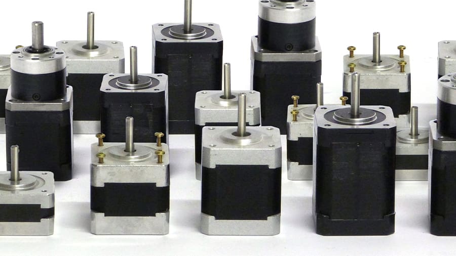
Stepper motors are by far the most used driving motor in the 3D printing world. These brushless AC motors spin in increments (steps) and have precise control of their rotation, even without position sensors for feedback. Since these aren’t highly complex mechanisms, they’re relatively inexpensive.
Stepper motors are identified according to their specifications and their nomenclature is standardized by the US National Electrical Manufacturers Association (NEMA). The motors most often used for 3D printing are named after this American association, usually referred to as “NEMA” followed by a number that indicates the size of its faceplate. For example, the popular NEMA 17 has a faceplate diameter of 1.7 inches (~43.18 mm).
For 3D printing, a torque range of 40 to 45 N·cm is sufficient, being the standard level for stepper motors. These motors provide a compromise between torque and speed, making them suitable for both heavier setups like most rectilinear printers and the faster-printing CoreXY style.
Leadscrews
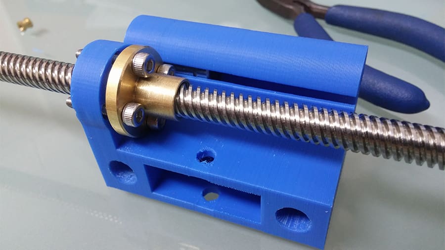
Another important mechanism is the leadscrew, which is a machine component specifically designed for translating rotational motion into linear movement. While there are different varieties of leadscrews, the most common are trapezoidal (ACME) leadscrews.
These rods are connected to the stepper motors with flexible couplings that allow a certain amount of end movement of the shafts, avoiding stress and wear in bearings and the motors themselves. This setup is usually used for a 3D printer’s vertical movement along the Z-axis.
Perhaps the greatest advantage of using leadscrews for linear movement is the significant push-force and self-locking ability, meaning they will (usually) not move if your printer unexpectedly loses power. This is one of the reasons they’re often used for moving the build platform. Leadscrews are rarely used for the X- or Y-axes, though, mainly because they are prone to severe backlash, leading to position inaccuracy, and they can be quite slow.
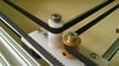
Timing Belt
Timing belts are “toothed” rubber belts that transfer rotational motion between two components, usually a motor and a pulley. The linear movement is achieved once a carriage is attached to the belt, with the motor being responsible for driving the whole belt-pulley assembly.
These belts are identified according to their tooth profile. A common timing belt used for 3D printing uses the “Poly Chain GT2” profile, and is often referred to as simply “GT2”. The motor pulley must have the same tooth profile as the timing belt for the assembly coupling to work properly.
In FDM printers, this system is often used for providing motion to the X- and Y-axes, where it’s crucial to have the belt tensioned correctly. This is why many 3D printers have built-in mechanisms for adjusting the belt tension.
Common 3D Printer Models
Now that we’re acquainted with the various types of 3D printers and their linear motion systems, let’s finish off by looking at some popular 3D printers to see these principles in real life.
Common Rectilinear 3D Printers
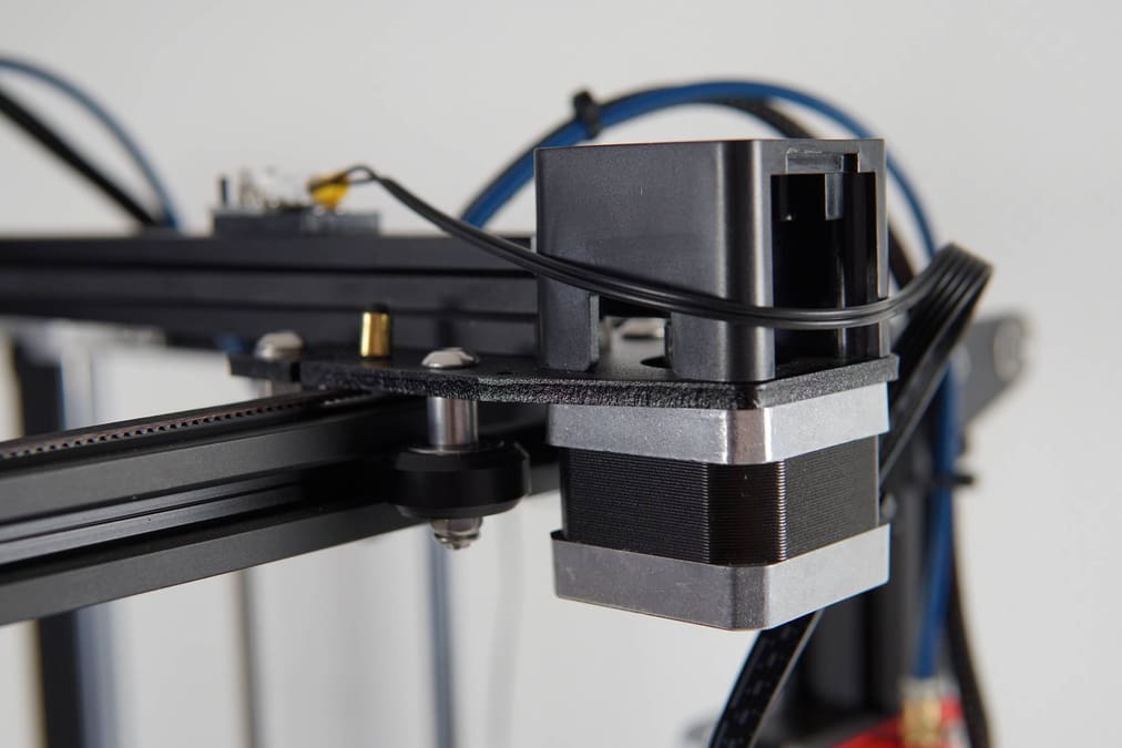
- Brands: The Prusa i3 series and MK4 and Creality’s Ender 3 series are XZ-head 3D printers, and so are several DIY models.
- Characteristics: These printers have a floating X bar that’s raised and lowered along the Z-axis, while the print bed moves back and forth along the Y-axis. One or two motor-powered leadscrews work to move the X gantry up or down, and another motor moves the printer’s toolhead via timing belts.
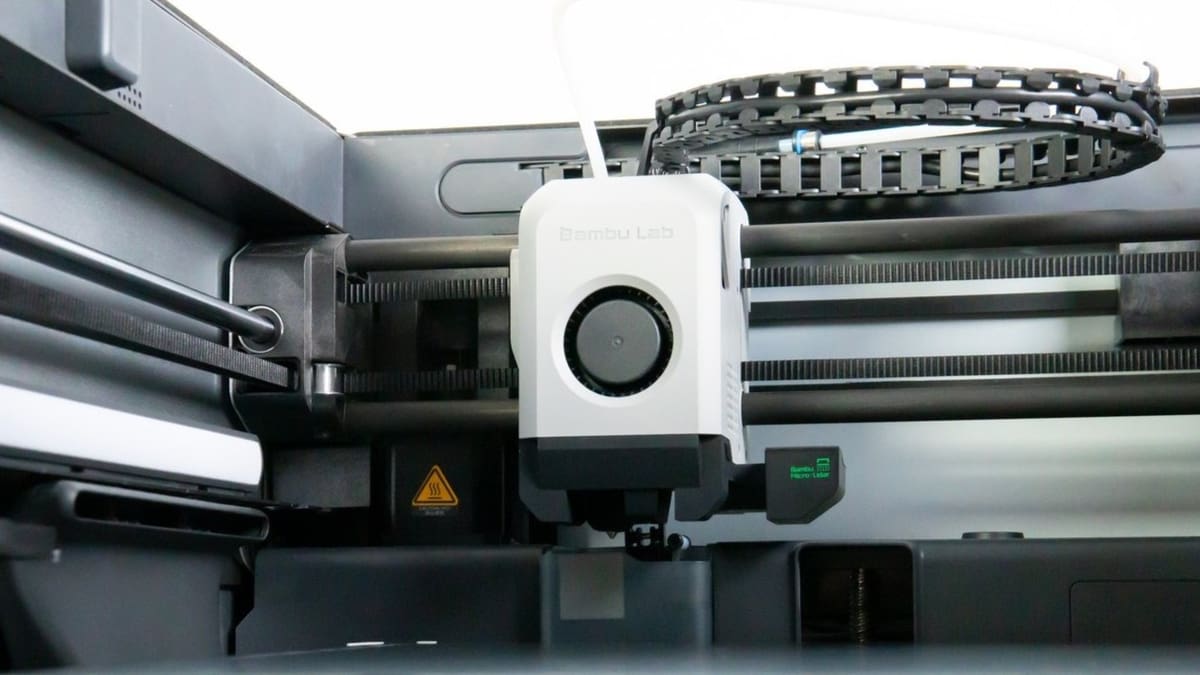
CoreXY-Style 3D Printers
- Brands: Bambu Lab’s P1 and X1 series are popular CoreXY options. Creality has also entered the CoreXY game with the K1. On the DIY side, Voron printers are a favorite open-source project in the maker community.
- Characteristics: CoreXY belts are responsible for XY motion, and both X and Y motors remain stationary, reducing the weight of moving parts.
Belt 3D Printers
Belt 3D printers fill a niche space within the 3D printing world, so the options for purchasing one are relatively limited:
- The Blackbelt 3D printer is perhaps one of the first consumer belt 3D printers to have reached the market and is still considered one of the best (priced accordingly).
- The Creality CR-30 (3DPrintMill) is Creality’s take on belt printers, being a cheaper alternative. Notably, it uses the CoreXY system for movement in the XY-plane.
Delta
Delta 3D printers have fewer design variations. Let’s look at two of the most popular:
- The RepRap Kossel, named after the German Nobel Prize winner of 1910, is perhaps the most known delta 3D printer. The Kossel open-source designs have a few variants within their “family”, such as the Kossel Pro and the Mini.
- FLSun V400 is another very popular delta 3D printer design.
SCARA
SCARA 3D printers aren’t a common sight. Still, there are a few examples available out there:
- The RepRap Morgan is a classic SCARA 3D printer design, being completely open-source, where parts are relatively easy to source.
- With a build volume of 200 x 200 x 150 mm, The SCARA Arm 3D printer can be purchased for around $300 and uses a belt transmission for even faster movement.
License: The text of "3D Printer Axis: The Basics Simply Explained" by All3DP is licensed under a Creative Commons Attribution 4.0 International License.