3D Printed Gearbox: How to Design Your Own Box

Gearboxes make the world go around, literally! Read on to learn the ins and outs of designing your own 3D printed gearbox!
A gearbox is an assembly of many gears to achieve a desired mechanical advantage. This mechanical advantage is a measure of the force or speed amplification achieved between two mechanical components.
If you look at a Penny-farthing bicycle, for example, the movement along the small radius of the pedals resulted in a long translation, thanks to the big radius of the front wheel. However, these bikes had some disadvantages and were a bit funny looking. It was later discovered that such conversion could be done more incrementally using gears.
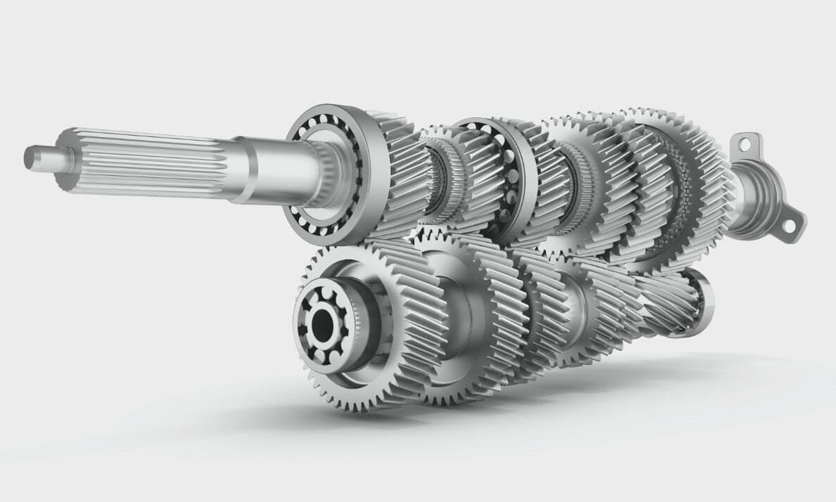
This principle is also found in motor engines where it’s usually called a transmission, and it’s used to convert the rotations of the small motor into increased displacement and torque for the big wheels. When you use the clutch, you’re changing what gear size the transmission is transmitted to.
Similarly, gearboxes are used in clocks to achieve the movement ratio necessary to move the hands of the clock correctly in seconds, minutes, and hours. Impressive, no? In this article, we’ll the basics of gearboxes as well as how to design and model them for 3D printing.
Gearbox Defined
Gearboxes refer to the complete assembly of the system and include all the gears, shafts, and the structure that contains them. This structure may be a box, but it also can be any other type of enclosure that fits the purpose of the gearbox. This structure can also have additional features like lubrication canals.
The term “gear train” may also be used. This is simply a more broad term, as “gearbox” is a bit more informal and generally refers to gear trains used for automotive transmission.
With that in mind, when we say “design a gearbox”, we are mainly focused on designing the gears that are contained in the system according to a desired ratio and applying this in design software, not necessarily the structure that contains the gears.
A Few Terms
When we’re talking about simple gear trains, there are a few important terms to know:
- Gear train (or gear set): The series of gears connecting the drive gear to the driven or output gear. From gear to gear in the train, each gear is handing off rotational direction, speed, and torque to the next.
- Driving gear: The first gear on the drive shaft, connected to the power source.
- Driven gear: Any gear that follows the driving gear.
- Idler gears: Gears that do nothing but reverse rotational direction between their neighbors.
- Shaft, axis: The rotational support structure connecting the gear to the gearbox.
There are a few ratios between the various parts that are essential to designing gearboxes:
- Speed ratio: Imagine you have a gear on a drive shaft rotating at a particular speed. For your application, you need an output shaft to rotate at a speed higher or lower than that of the first. By a series of connected gears between the driveshaft and an output shaft, you can take your driveshaft rotational speed and convert it to the needed rotational speed at the output shaft. This is called “speed ratio”, calculated by the ratio of drive gear tooth count to output gear tooth count.
- Torque ratio: As with the speed ratio, a gearbox provides a means to convert available torque at the drive shaft to the needed torque at the output shaft.
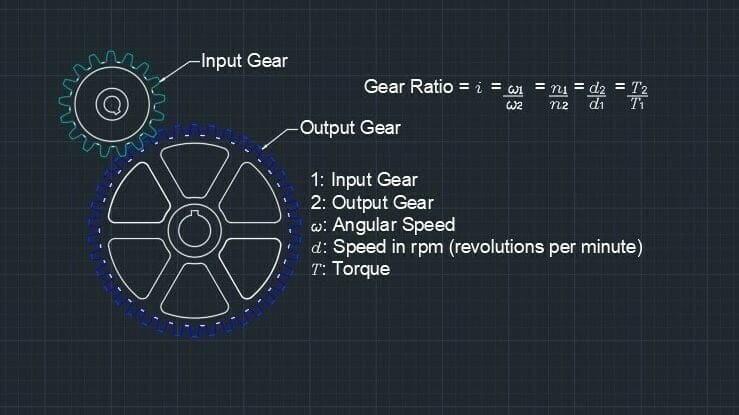
- Gear ratio: The gear ratio is commonly denoted by ‘i’. How to calculate it is shown in the image above, and it’s used to determine the speeds and torques discussed previously.
It’s important to take into account that two gears, no matter their size, will move at the same speed if they’re attached to the same shaft. Two gears attached at the same shaft and moving at the same speed but with different radii, however, will have a different torque. This is the case because torque is a function of the radius.
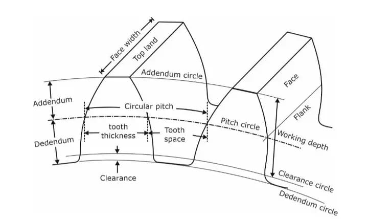
Finally, the following terms are used in making gears and gearboxes. You’ll see them in the Fusion 360 Spur Gear example that we’ll do later.
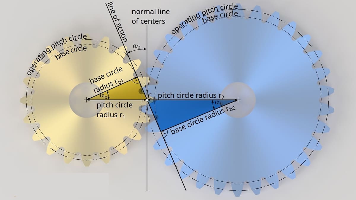
- Pitch diameter (or pitch circle, base circle): The diameter of the gear, which is used for spacing gears. This is not the same as the outside diameter of the gear.
- Module: The pitch circle diameter divided by the number of teeth
- Pressure angle: Usually 20° or 25°, though 14.5° has been used in the past
For gears to mesh correctly, they must have the same module and pressure angle.
Types of Gears and Gear Sets
Below is a list of gears and common applications for each. Keep in mind, though, that we’re makers and disrupters, so feel free to bend the rules and create new applications.
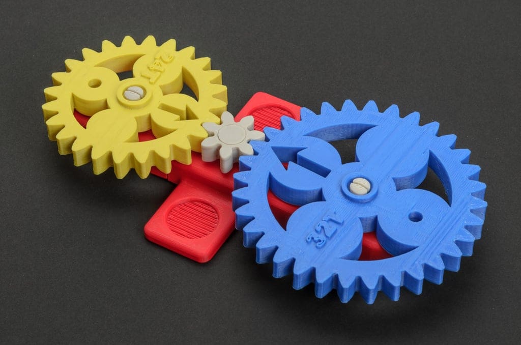
- Spur gears: In a spur gear, the ridge of each tooth is parallel to the axis of rotation. In this way, teeth are used to transmit rotation from one shaft to another parallel shaft. In 3D printing, spur gears are often employed by extruders to drive the filament into the hot end. Many versions exist, including Wade’s Geared Extruder, a well-known extruder in the RepRap community.
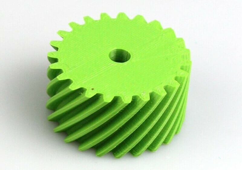
- Helical gears: In these types of gears, the teeth are inclined to the axis of rotation. Helical gears can be used in the same way as spur gears but run quieter because the teeth engage more gradually.
- Bevel gears: These gears can be spur or helical, but the teeth rest on a base resembling a cone rather than a cylinder. The resulting angle can be used to transmit rotation between intersecting shafts.
- Worm gears: These gears transmit rotation between non-parallel and non-intersecting shafts. The worm gear looks like a screw and is the driving gear.
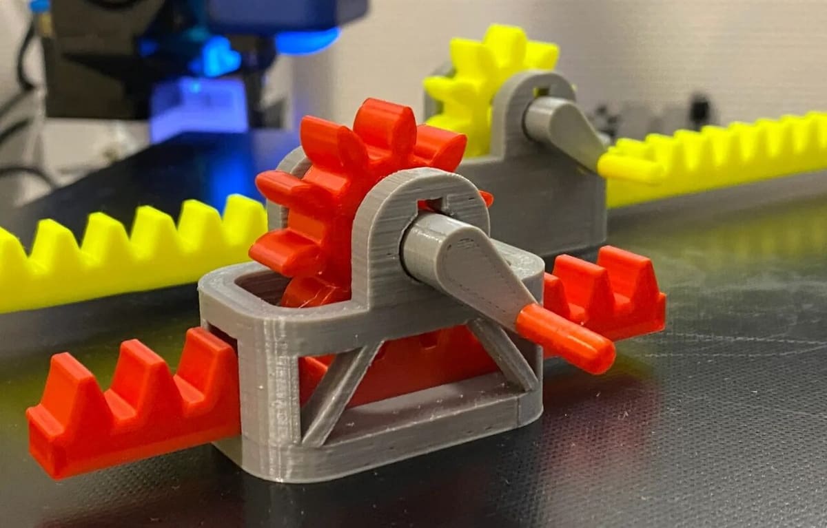
- Rack and pinion: These two parts consist of a standard gear (either spur or helical) and a flat component with teeth. Together, they work to convert rotational motion to linear motion or vice versa.
- Internal gear and pinion: This is similar to a rack and pinion, but the rack is effectively curved around the standard gear, forming a loop and looking something like a gear cut-out. This setup is getting a bit more complex.
Involute Gears
Along with gear types, it’s worth mentioning the involute gear profile. Essentially, this is a gear tooth design that’s optimized to reduce noise during operation and maximize efficiency of the gear train. The involute sounds neat and looks nice – a combination of form and function we can all appreciate.
You can check out online references such as Engineers Edge to learn more about the design of the involute gear. For now, it’s enough to say stick to the involute gear design if possible and avoid the noisier, less-efficient straight-toothed gear.
Assembly
Gearboxes’ main components are the gears, of course, but these can’t simply float. Therefore, how we assemble and store them is also important. As the gears need to transmit torque, you want to avoid any slipping between it and the shaft because that’s energy wasted and precision lost.
There are some ways to ensure the correct assembly of the gears onto the shaft:
- Option 1: Assemble the shaft by pressure, making the bore diameter a tight fit. In 3D printed applications, you can buy a metallic rod for the shaft, then heat it up when inserting it into the gear to ensure a tight pressure fit. This option is ideal for small parts, but you have to avoid slipping. Another possibility for 3D printed gearboxes is printing the gear with the shaft as one piece, if the application allows it.
- Option 2: Use a flange to tighten the gear with screws. This may not be possible for very small gears, but it’s great for large gears that transmit a lot of torque.
- Option 3: Use a key. You’ll have to somehow also attach the positive key part to the shaft, which may not be possible depending on how you’re constructing the gearbox. For small gears, especially 3D printed, this may be hard to achieve.
- Option 4: Use a polygonal cross-section so there’s no chance of slipping. Once again, you have to consider possible rods for such an option. Some polygonal profiles are available commercially, so just keep in mind to look out for what’s out there before making a decision.
Design Process
Whenever you’re designing gears for any application, there’s a general process you always follow. Even though the results will vary in every case, this process ensures the end product will work as intended.
- Consider the application: How will you use your 3D printed gearbox? Think about what you want to do. Whether that’s changing rotational direction, shaft speed, or shaft torque – all are usual reasons to employ a gearbox. This may also tell you the type of gear you need. For example, if you determine you need a change in direction, you know you’ll be employing bevel gears.
- Consider the manufacturing process: If the gear is created by smelting hardened steel, for example, the resistance of the material is much higher. As we’re focusing on 3D printed gears, it’s important to consider the limitations of 3D printing, including available materials as well as dimensional accuracy and capacity. A great resource to consult is our article on 3D printing gears, which touches on 3D printed gear test files and use, 3D printer capacity, gear thickness, strength, materials, and some rules of thumb.
- Calculate gear relations: The design of a gearbox will usually have the following parameters: an input condition (speed, for example) and an output parameter (another speed). With this, you can calculate the required ratio, diameters, and pitches of the gears. If there are any additional parameters (like a size limitation) or if the change is too drastic, this may also reveal the need for additional gears to achieve the required mechanical advantage.
- Model Gears: Now that we know the dimensions of the gears, the next logical step is to model them to be 3D printed.
- Model Casing: How will the gears be held together?
Resources
There are quite a few resources out there to help you design a gearbox. “A Practical Guide to FDM 3D Printing Gears” is a great resource for 3D printing gears that’s available on Instructables. For gear train math, see the article “Gear train“, which describes mathematical details for simple, compound, and other gear set types. Also check out the “How to Determine Gear Ratio” article from WikiHow that deals with the math of gear trains.
Examples
Before starting head-on with the tutorial, the following are some 3D printed gearbox projects that you can try yourself to get a feel of how gears work, catch some things that you have to watch out for, or to just check out some applications:
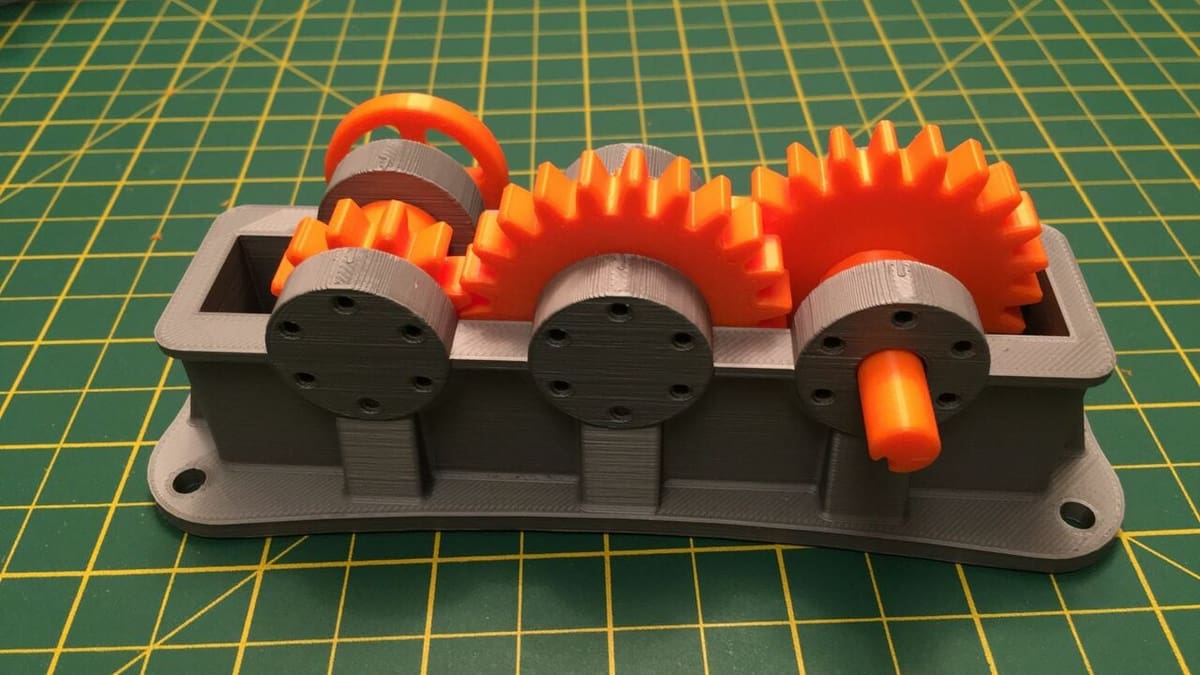
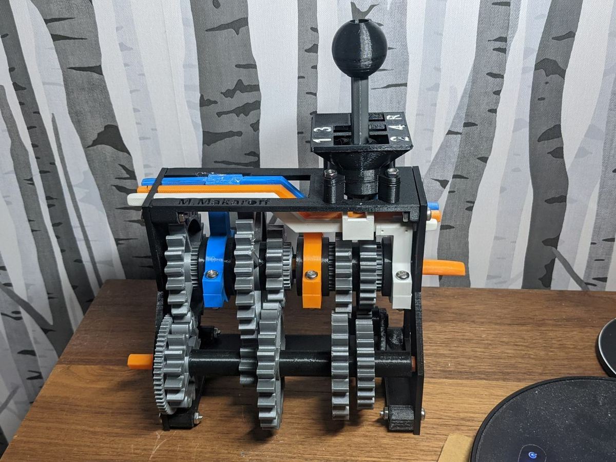
- Car transmission gearbox: This project is a great introduction to gearboxes, and it works very similarly to the gearbox in a car. Therefore, you can visualize the effect of the mechanical ratios, and it works like a car gearbox with a clutch.
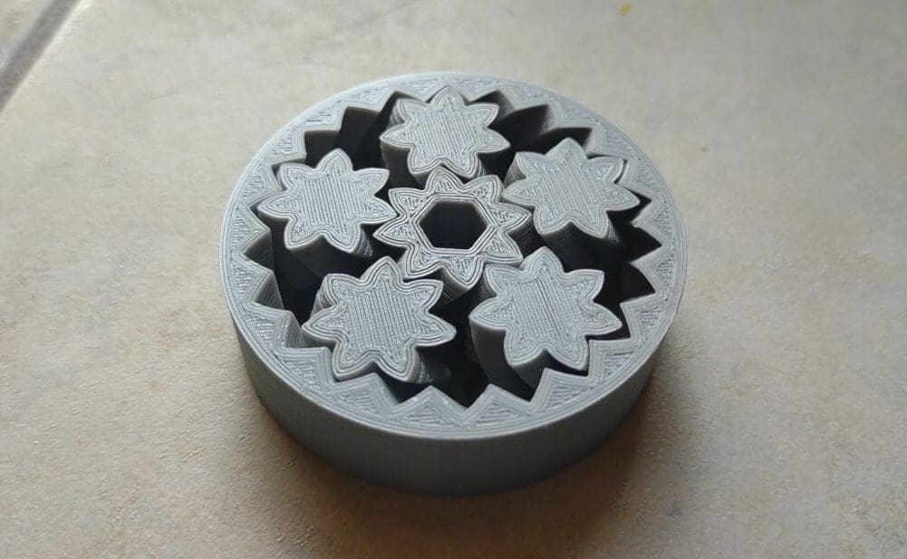
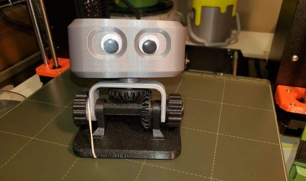
- Planetary gearbox: Beyond standard gearboxes, it’s interesting to see other applications where the thought is more outside of the (gear)box. The creator explains the system and provides video of the motion with a differential gear doing transmission
- Herringbone gearbox: This type of gear train is typically used to test limits of size, inertia, and conversion ratios. You’ll find many examples on YouTube in which creators add as many gears as possible and as big or small as possible to see how much energy is needed to keep the gearbox moving and to test its limits.
Tutorial
To learn how to apply all this knowledge, let’s design a basic gearbox together. We’ll follow the same process that we outlined above.
Even though many software options are available for this, we’ll be using Fusion 360. Fusion 360 has free versions for hobbyists and start-ups, making it accessible for many more users. We’ll assume that you know the basics of the UI and how to navigate around generally the software. However, if you don’t, you can take a quick look at our article on modeling in Fusion 360.
Getting Started
For this project, let’s make a gearbox that will decrease the shaft speed of a motor by half. If, for instance, the input motor shaft speed is 500 rpm, the output shaft speed should be 250 rpm. This will come as a result of the tooth count ratio between the input and output gears connected to these shafts.
Let’s add an additional gear between the input and output shafts for a total of three gears. This will allow the input and output gears to have the same rotational direction.
The first gear, connected to the motor drive shaft, is the driver. The middle gear is the idler, which is simply there to reverse the direction of rotation. The third gear, connected to the output shaft, is the driven gear. To make matters even simpler, we’re saying the driver gear has a diameter of 30 mm and 12 teeth.
With such conditions, the driving gear and all subsequent gears modeled from it will have a pressure angle of 20°, a module of 2.5 mm, be extruded to a depth of 4 mm, and have a bore diameter of 5 mm.
Step 1: Designing the Gears
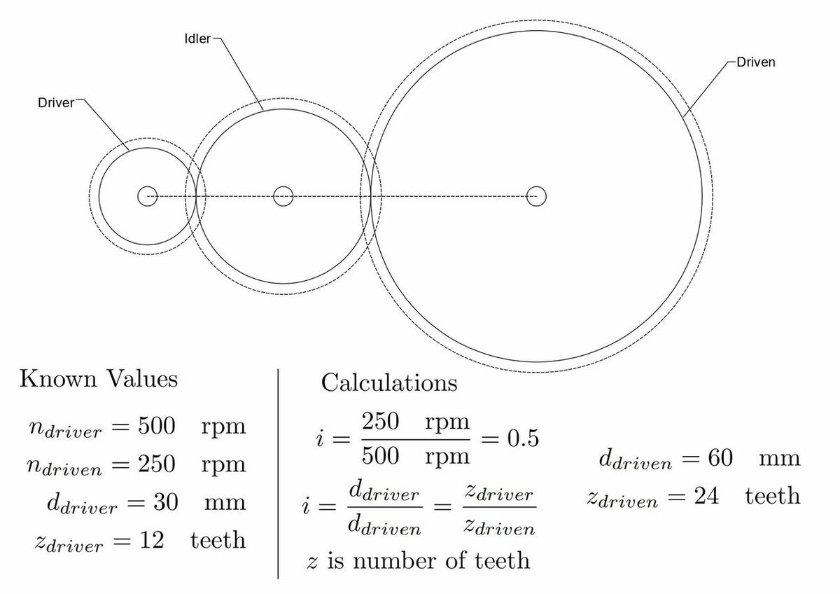
The first step will be to calculate all the dimensions and characteristics of the gears, including the gear ratio as well as the diameters and number of teeth of each gear. This will give us the necessary data to model them. All the calculations are shown in the image above to make it easier to follow along.
For our example, we’ve calculated the following parameters:
- Gear Ratio: i=0.5 because we said we want to reduce the speed by half. This is the total value, from the driver gear to the driven gear, but remember there is another gear in the middle.
- Diameter and teeth of the driven gear: i=ddriver/ddriven = zdriver/zdriven where z is the number of teeth. Therefore ddriven is 60 mm and zdriven=24 teeth.
- Diameter of the idler gear: Because this gear is an idler gear, it can have any size as long as the aspect ratio is maintained. The ratio of the driver gear to the idler gear will be called i1 and the ratio of the idler to the driven gear will be i2. i=i1*i2=0.5. If we set the diameter of the idler gear to 50 mm, then i1=0.6 and i2=0.833, effectively keeping the ratio.
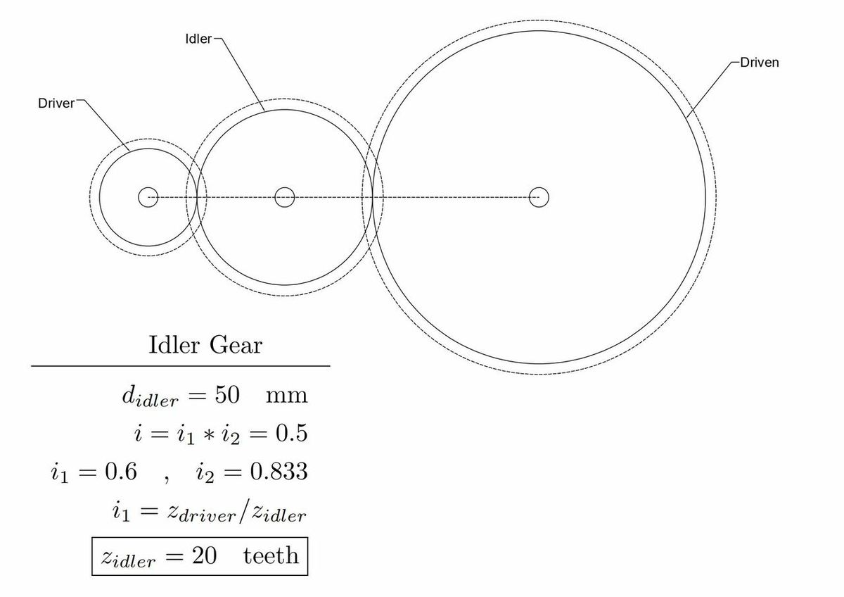
- Teeth of the idler gear: Using this same relation for the teeth, now we know that i1=zdriver/zidler, as the idler is being driven by the driver gear. We use i1 instead of i2 simply because 0.6 is a nicer number to work with, but using i2 should arrive at the same result. Just keep in mind that i2 would be between the idler and the driven gears. With this formula, we get that the idler gear will have 20 teeth.
- Module: The module is the ratio between the diameter and the number of teeth, therefore this is the number that will give us the desired diameter. It should be consistent across all gears to make them assemble correctly. So, we can use any gear data to calculate it. Module = d1/t1 = d2/t2 = d3/t3 = 60 mm/24 teeth = 2.5 mm.
Note that the diameters obtained are the nominal diameters of the gears. They’re mathematical diameters that can’t be measured with the measuring tools for a real gear. That being said, they are useful for standardizing gear sizes and are incorporated in design guides and modeling software.
Step 2: Gear Add-in in Fusion 360
Now that we know the parameters of the gears, it’s time to get modeling. We’ll do this in Fusion 360, and to avoid having to model from scratch, we’ll make use of an add-in that’s included in all versions of Fusion 360.
Here’s how to install it:
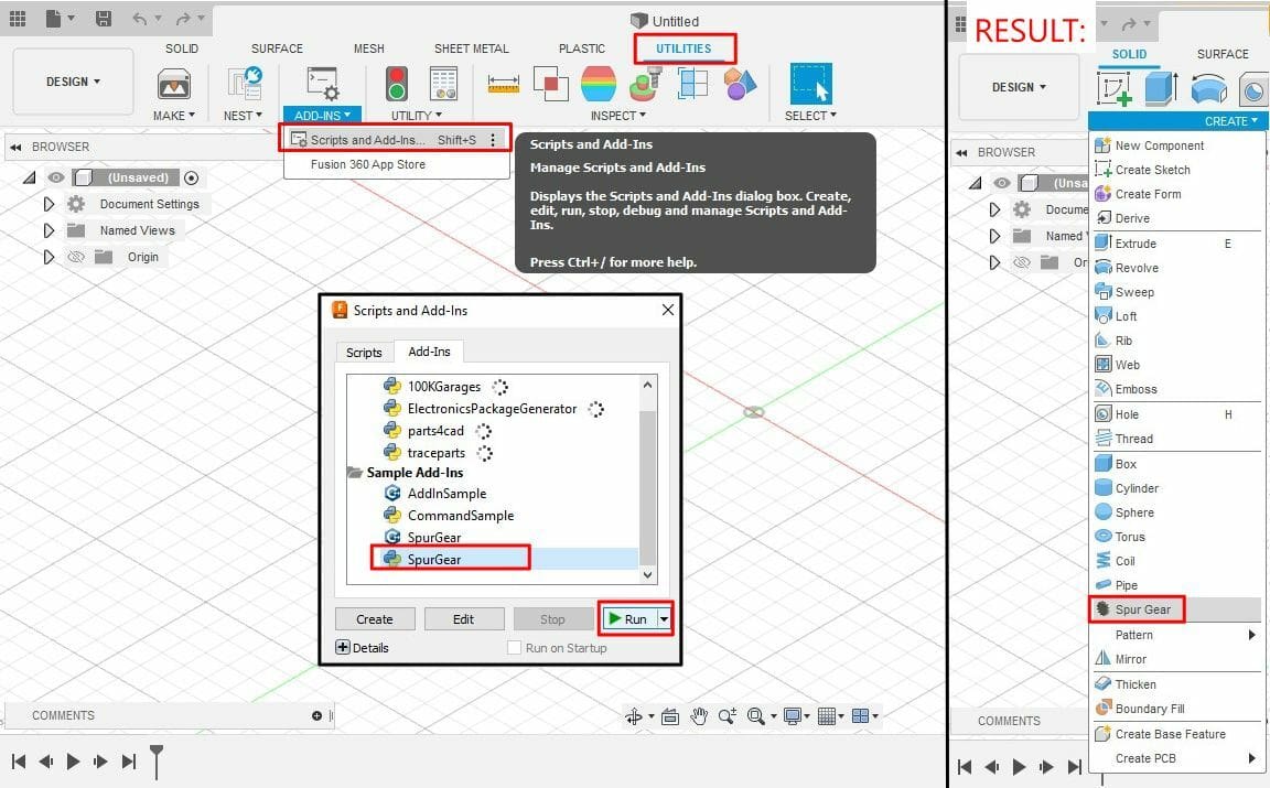
- Go to the Design workspace, and in the “Utilities” tab, open the add-ins menu.
- In the “Scripts and Add-ins” dialogue box, go to the “Add-ins” tab.
- Select “Spur Gear”, then click “Run”. You can select either the C++ option or the Python option; they work the same way. We’ll be working with the Python option (the one with a blue and yellow cross logo).
The add-in is now installed. We can access it by clicking the “Solid” tab on the Toolbar, followed by the “Create” dropdown menu at the very bottom, then selecting “Spur Gear”.
Step 3: Create Driver Gear
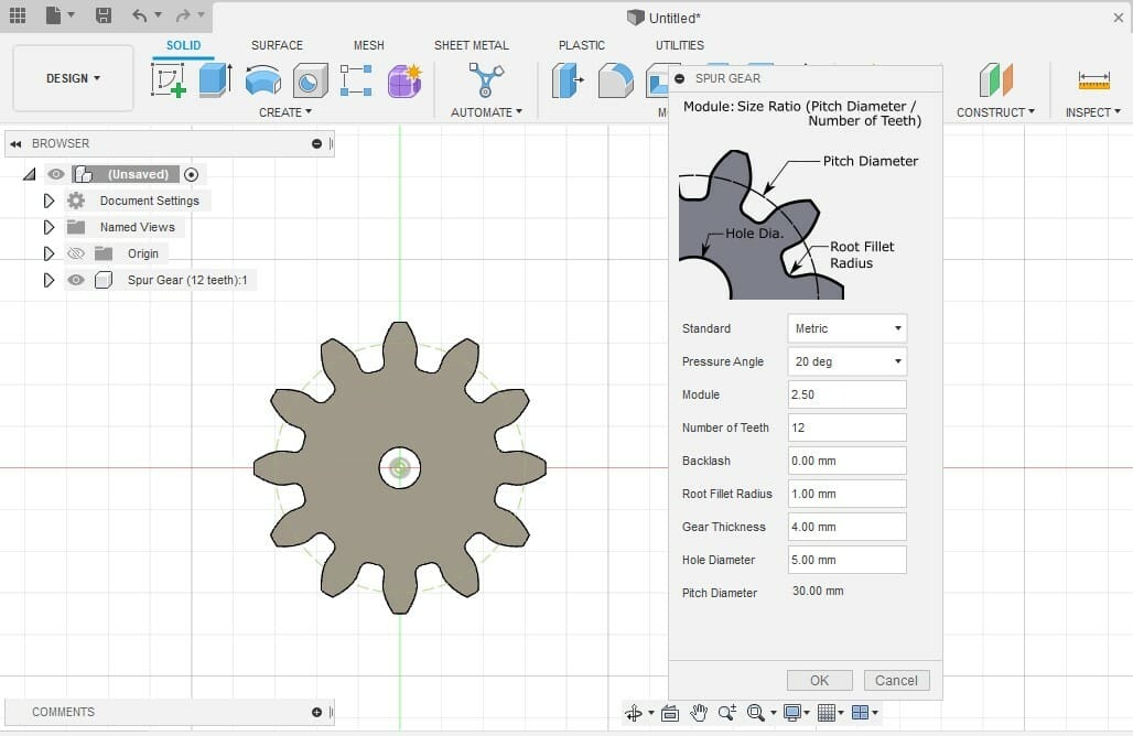
The order in which you create the driver, idler, and driven gears doesn’t really matter, but we’re specifying for clarity’s sake. When you select the Spur Gear tool, a dialogue box opens with a set of parameters. Input the parameters we’ve established for the driver gear as follows:
- Standard: Metric (This refers to the system of units)
- Pressure Angle: 20°
- Module: 2.5 mm
- Number of Teeth: 12
- Backlash: Leave the default values suggested by Fusion 360
- Root Fillet Radius: 1 mm
- Gear Thickness: 4 mm
- Hole Diameter: 5 mm
- Pitch Diameter: Will populate automatically based on the previous inputs
After you’ve added all of the values, press “OK”.
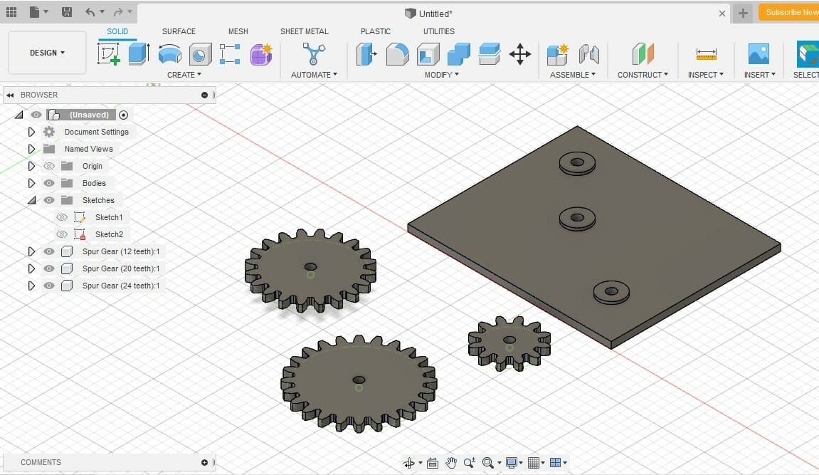
The gear is now added to the Viewport and listed in the Browser. You can see that all of the sketches related to it (inside, outside, and nominal diameter, for example) are also included in the drawing. We won’t use these for anything, but they could come in handy if you need to provide technical drawings of a project.
Step 4: Create the Idler & Driven Gears
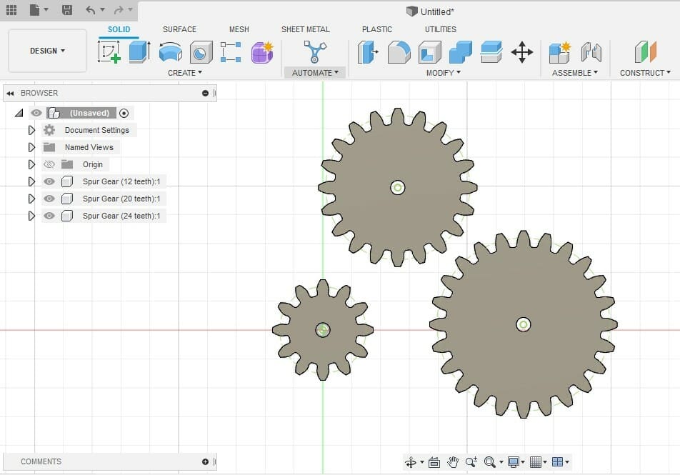
Now, we repeat the previous step but for the Idler and Driven Gear. For the idler gear, we’ll input the following:
- Standard: Metric (system of units)
- Pressure Angle: 20°
- Module: 2.5 mm
- Number of Teeth: 20
- Backlash: Leave the default values suggested by Fusion 360
- Root Fillet radius: 1 mm
- Gear Thickness: 4 mm
- Hole Diameter: 5 mm
- Pitch Diameter: Will populate automatically based on the previous inputs
Once again, after adding all the values, press “OK”. Note that only the number of teeth changed, as the module takes care of assigning a diameter of 50 mm already. This is implicit in the calculations we did.
Lastly, let’s add the driven gear:
- Standard: Metric (system of units)
- Pressure Angle: 20°
- Module: 2.5 mm
- Number of Teeth: 24
- Backlash: Leave the default values suggested by Fusion 360
- Root Fillet radius: 1 mm
- Gear Thickness: 4 mm
- Hole Diameter: 5 mm
- Pitch Diameter: Will populate automatically based on the previous inputs
And as you might have already guessed, press “OK” once the values are in.
Note that the gears in the image are not placed with the teeth coincident with each other. The intention is to print these gears, therefore it doesn’t matter how they’re placed in the CAD program. Their placement would only matter if you want to animate their motion.
Step 5: Modeling the Gear Enclosure
To keep things simple, the structure will consist of a rectangular backplate that can fit all of the gears. It’ll also have some risers to reduce the friction between the gears and the backplate. Before we get started with the modeling, we’ll need to determine some measurements (and yes, we’ll have to crunch some numbers again!).
Measurements
For this basic example, we only need to know the outer diameter of the rectangular backplate as well as the location and diameter of the bores. For specific applications, you can get creative and add more detail to the casing.
- Backplate: The backplate should be large enough to fit all three gears. 120 mm width x 100 mm height should suffice.
- Bore placement: The distance of where the bores should be located is simply the sum of the nominal radius between gears. We’ll call r1 the radius of the driver gear, r2 the radius of the idler gear, and r3 the radius of the driven gear. d12 is the distance between the driver gear and the idler gear, equal to r1+r2=40 mm. d23 is the distance between the idler gear and the driven gear, equal to r2+r3=55 mm.
- Bore diameter: The diameters of the holes should be such that the rods can move freely. This would ultimately depend on your printer tolerance, which is 0.15 mm for us. Therefore, we’re doing the holes of the backplate with a diameter of 5.3 mm. Note that we didn’t do this for the gears because we want them to have a tight fit with the rod.
Modeling
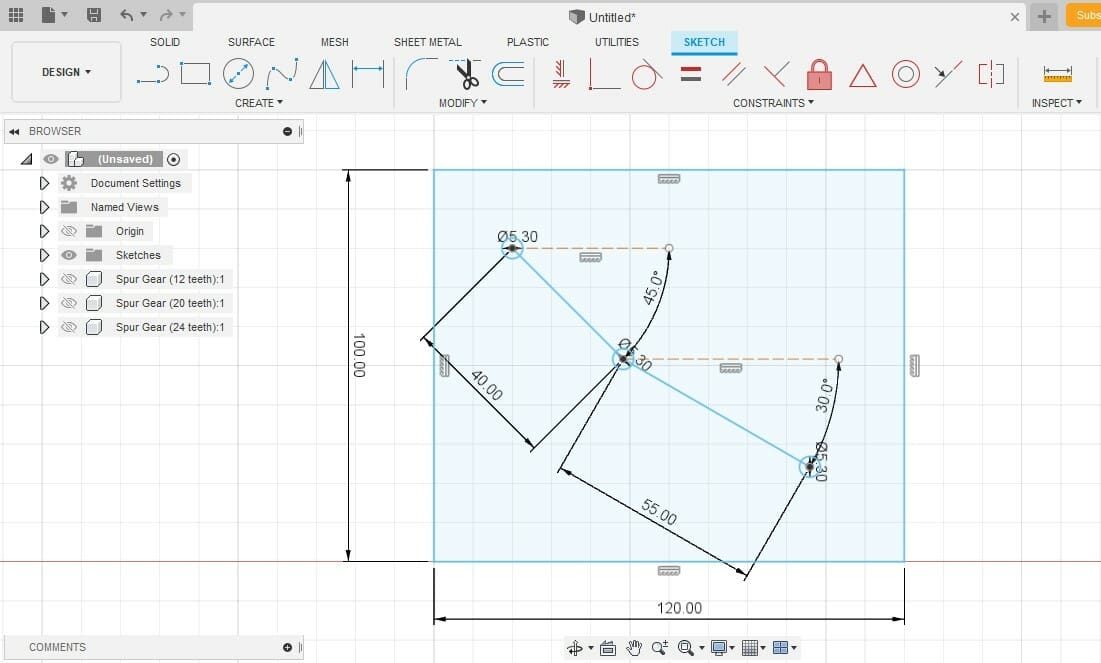
Now that we have the base measurements, all that’s left is to translate these into Fusion 360. You can see the image above to compare what the final result should look like.
- Create a sketch of the top plane.
- Use the Rectangle tool to create a rectangle and assign dimensions of 120 mm width x 100 mm height. You can use the Tab key to switch between the vertical and horizontal coordinates.
- Starting from any point on the top left of the rectangle, create a line of 40 mm at 45° clockwise from the horizontal. Once again, you can use the Tab key to switch between the length coordinate and the angle.
- Parting from the endpoint of the previous line, draw a 55-mm line at 30° clockwise from the horizontal.
- On each point created by these three lines (three points in total), draw circles of 5.3-mm diameter each.
- Finish the sketch.
- Using the extrude tool, extrude the backplate to have a thickness of 4 mm.
Step 6: Creating the Risers
The risers will reduce the area of the gear that’s in contact with the back plate. These work as washers to reduce friction and prevent restriction of movement. Should you have any warping (hopefully not), the gears would still be useful, thanks to the risers.
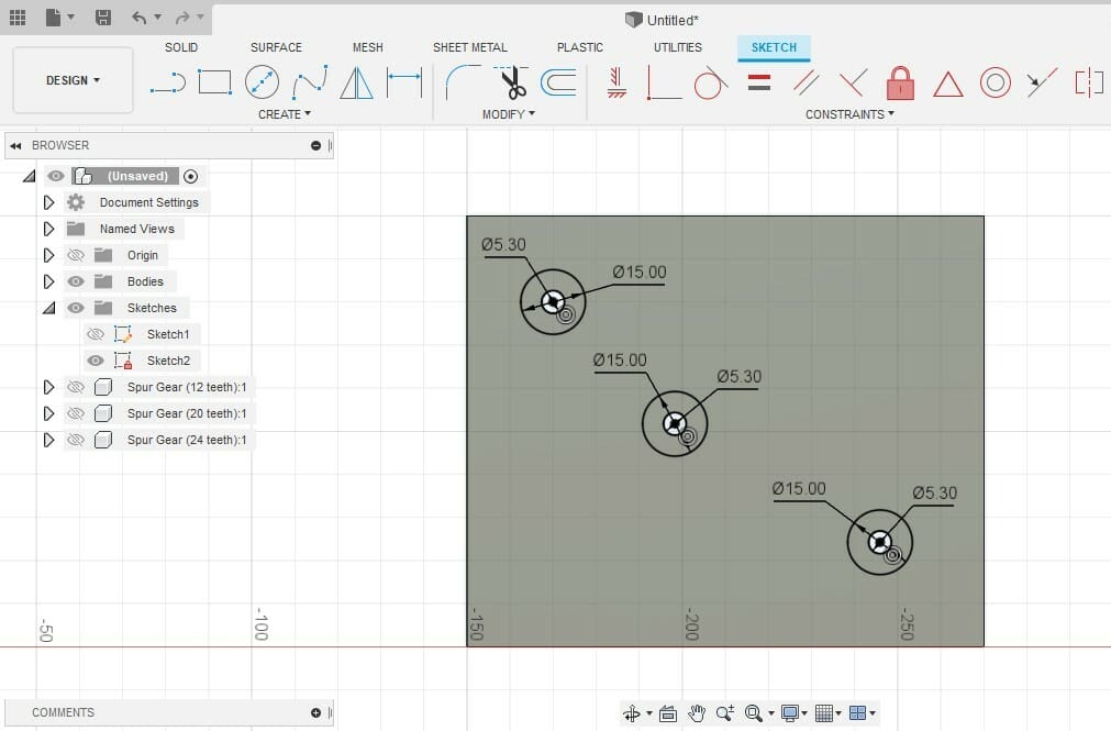
- Create a new sketch using the surface of the backplate as the base.
- Draw a circle to create the inside diameter of the risers. This diameter is simply the same as the holes in the backplate.
- For the outer diameter, draw a bigger circle. Any diameter that’s smaller than the gear should be fine. The outer diameter we’ll use is 15 mm.
- Use the Extrude tool to extrude the washer with a thickness of 1.5 mm.
We won’t cover the modeling of the shafts, as we’ll use commercially available 5-mm rods, but these could be modeled very easily as cylinders if you want to 3D print them as well. You could, in fact, print them as one piece with the gears, completely eliminating any assembly issues.
Design & 3D Printing Tips
Now that the design is ready, all that’s left to do is to print it. In this section, we’ll give you some tips on how to achieve the best results.
Design Tips
An important thing you’ll notice with the designs shown in the examples is inertia, which is related to the mass of the gears. Because of inertia, the gears will tend to want to stop, and they’ll eventually do so unless you include a constant input, such as a motor, to keep them moving. The more inertia they have, the greater the motor you’ll need.
Inertia can be reduced by reducing the mass of the gears. For bigger gears, you can do this by hollowing out non-crucial parts of the gear.
Printing Tips
Now that it’s time to bring the gears out of the virtual world and into the real one, let’s check out some tips to get good 3D printing results. These tips concern the quality of the print and also how to improve the durability of the part.
- The higher the resolution (and quality) of the print, the more resistance and less wear the gears will suffer.
- Ideally, gear teeth shouldn’t go through sanding, as this may affect the dimensions and therefore accuracy. This is a big issue with CNC wooden gears, but it can thankfully be avoided in 3D printing with settings for high-quality prints, even if the print does take a bit longer.
- Because of how prone to wear gears are, more resistant materials like ABS may work better. If you use ABS and want to fit shafts using pressure and a heated rod, be cautious that ABS releases gasses when hot. It’s good to keep in mind the health and environmental impacts of materials.
License: The text of "3D Printed Gearbox: How to Design Your Own Box" by All3DP is licensed under a Creative Commons Attribution 4.0 International License.