3D Modeling for Printing: Best Practices

When 3D modeling for printing, your choices should account for the print process. Let's review some best practices!
Many Options
3D printing represents a manufacturing process that’s very different from all others. So how should someone go about designing a 3D model with the intention of it being 3D printed? The ways are simple, but it all depends on which 3D printing process is going to be used. Each requires special design attention before a model can be sent off for printing, and each has unique benefits and drawbacks.
In this article, we’ll take a look at the most common manufacturing complications of FDM, SLA, and SLS and how to address them when a model is in the design phase.

FDM
Fused deposition modeling (FDM) is by far the most popular process for hobbyists in the realm of 3D printing. FDM printers are also the lowest-priced and most commonly used. Because of this, a lot of pre-existing 3D models are designed around the workings of FDM printers.
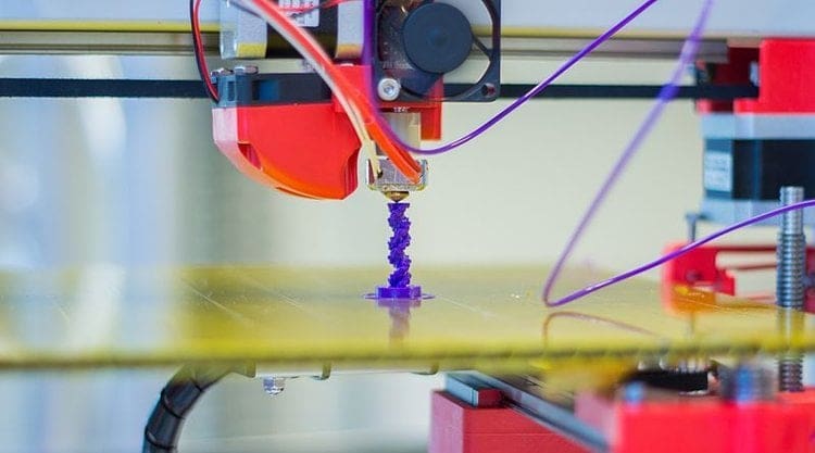
As building material, an FDM printer uses thermoplastic material, which is usually supplied as filament. This filament is melted and extruded through a nozzle, which deposits the material in layers to eventually form the finished model. So what needs to be considered when designing for FDM?
Build Plate Adhesion
A model should ideally have a large, flat side that can be oriented downward. This will provide enough surface area to sufficiently adhere to the build plate as the first layer is printed. If the model doesn’t have sufficient adhesion to the build plate, it could detach during printing, leaving an incomplete print, wasted material, and a frustrating trip back to the digital drawing board.
Outside of designing, quick tricks to ensure build plate adhesion include adding a raft, setting a brim, or enabling supports. All of these options will increase the area of the first layer, making the print more likely to succeed.
Supported Parts
FDM printers extrude from the build plate up, so a model shouldn’t have any parts that are disconnected from the main body or any unsupported surfaces above the build plate. You can’t print in thin air with any 3D printing process, so make sure to design each part so that it can contact the build surface.
If floating parts can’t be moved out of position or designed to touch the build plate, supports can be generated in slicer software. This will give floating surfaces and overhangs a better chance of printing successfully.
Overhangs
Overhangs are one of the biggest drawbacks of FDM 3D printing. When molten material exits the nozzle, it needs to be supported by something in order to keep its shape while it cools and solidifies.
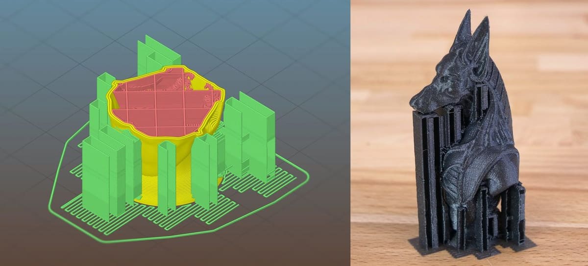
While modeling, best practice is to have overhangs supported on both sides or to use angles of less than 45 to 60 degrees to the vertical (depending on your printer’s capabilities). If you absolutely must have an overhang greater than this, it’s advised to keep it small, protruding less than 5 millimeters into thin air. Following these guidelines, one can get away with printing without supports.
Of course, adding supports in your slicer is always an option. Just note that, for some models, removing them can be tedious, time-consuming, and sometimes even impossible. Also make sure that hollow parts don’t have excessive unsupported overhangs within them, as adding supports here usually isn’t an option at all.
Accuracy & Deformation
Despite its popularity, FDM can be sloppy and rough when compared to other processes. There are a few aspects of a typical printed part that should be thought of during the design phase, namely holes.
Horizontally-oriented holes of medium to smaller sizes are often deformed during the FDM printing process. Furthermore, supports can’t easily be removed from small or deep holes, so it’s recommended to keep them large or oval-shaped to account for shrinking and deformation. Another option is to purposefully design them to be small and later enlarge them with a drill.
Threads pose another problem. Threaded parts produced with FDM often don’t fit with matching non-printed components unless the dimensions are altered pre-print to account for thermal contraction in the printed material. Rounding threads to create a smoother profile is also a good idea.
Infill
A very important aspect to consider is infill. With FDM printing, parts that are modeled solid have the option in the slicer software to be printed with a patterned, mostly hollow internal geometric structure, rather than being solid material. Keep this in mind when designing large parts to be printed, that they don’t have to be solid if it’s going to be printed with FDM.

Material
With FDM printing, the material can be quickly changed between prints, and options such as flexible, food-safe, glow-in-the-dark, multicolor, and other special property materials can be used to enhance your prints. FDM materials can also include additives such as wood fibers, metal, and carbon fiber.
When designing, it’s good to think about the eventual material, especially regarding its strengths and weakness. For instance, ABS is strong and heat-resistant but warps easily while printing. Therefore, for a wider part, a similar material like PETG or Nylon may be a better choice. It all boils down to what you’re comfortable printing with, and what purpose the finished part will have.

SLA
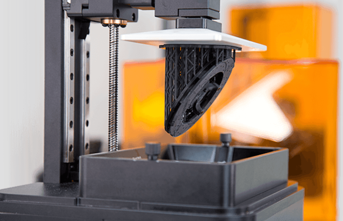
Stereolithography (SLA) typically uses a bath of resin, from which layers are selectively solidified by a laser to form a finished model. In most cases, the process uses a build plate that’s inverted compared to FDM. The build plate is dipped down into the resin bath from above, and the model is printed upside down.
The advantages of SLA are vastly superior resolution and part finish at the expense of some strength and durability. This, along with a few other key factors, influences how one would go about designing a model for SLA 3D printing.

Drainage
While the FDM process selectively extrudes material, the SLA process selectively solidifies a photopolymer resin, so models can be printed hollow, or partially hollow. However, this must be done properly, otherwise, the result will be a sealed model filled with uncured resin.
A popular technique is to design a model to be hollow and include drainage holes. When doing this, make sure to place holes in enough places to allow the resin to be easily drained, without marring the final appearance of your model.
Surface Area & Supports
During printing, SLA continuously peels the freshly cured layers off of the film at the base of the resin vat. This process can introduce a decent amount of force on the print, sometimes causing it to fail by delamination, where the print becomes unstuck from the build plate.
When it comes to design, the best way to avoid this is to ensure your print has a wide enough base. This will increase the surface area resting on the build plate, and this extra adherence will better cope with delamination forces.
Naturally, if this isn’t possible, you can always rely on supports (which also help with overhanging details). In this case, your design still comes into play, as you’ll want to make sure to provide features that supports can “hold on to”.
Detail & Deformation
Unlike FDM, SLA is able to produce very detailed models. Despite their fragility and longer print times, the result is typically superior in resolution and precision. For this reason, designers have the opportunity to create features that aren’t possible with FDM. This includes small-sized holes, threads, interlocking parts, complex textures, and fine details.
Trapped & Residual Resin
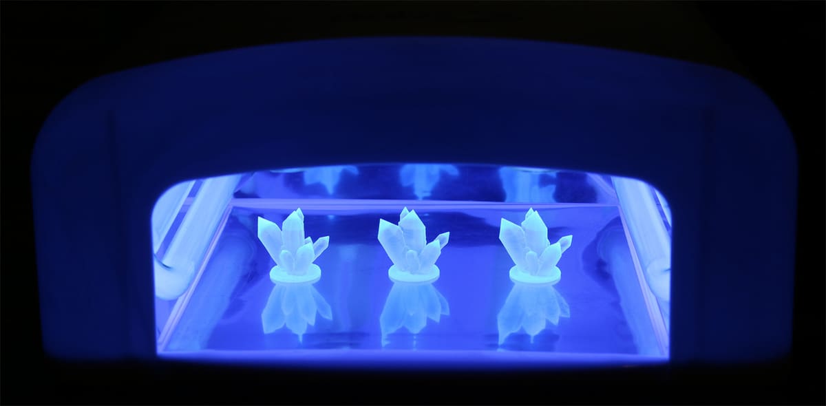
Resin can often become trapped in small nooks and crannies within a model. If any small crevices or interlocking joints aren’t cleared of resin before the curing process, the liquid can cure and cause problems, for example freezing a joint in place.
One way around this is to entirely avoid interlocking parts, and print separate components to be assembled later. In the case that this is not possible or desirable, the alternative is to provide access for the resin to drain from these areas, or clearance to clean and dry the affected parts prior to curing.

Material
When printing in SLA, there are fewer choices in resin compared to FDM. That said, enhanced performance materials do exist, like durable resin or castable resin. If you’re planning to use such a material, think about what sort of performance it will allow and design with these possibilities in mind.
SLS
Selective laser sintering (SLS) shares properties with the SLA process. SLS uses a print area that’s entirely filled with material throughout the printing process, selectively solidifying a model in layers with a laser, similar to SLA. The main difference between SLS and SLA is that, while SLA uses liquid resin as the print material, SLS uses powdered plastic (or metal in higher-power machines).
While this unique process eliminates some of the issues of SLA, there are still some things that need to be taken into consideration.
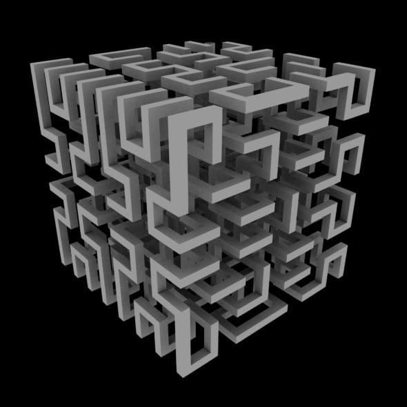
Unsupported Features
Due to the nature of SLS printing, the unsintered powder surrounding the model automatically supports the printed component, meaning no additional supports are required. As such, models can have any number of complex geometries, including those that would require extensive or impossible post-processing work to remove otherwise necessary support structures.
Hollow Spaces
Similar to SLA, in SLS, any hollow spaces or complex internal infill structures within a part will naturally contain residual powder after printing. Since the powder is more difficult to remove than resin, it’s often better to redesign any hollow parts to be solid or incorporate easy interior access to remove the unsintered powder.
Durability & Precision
As opposed to SLA models, which are known to be more fragile than ones printed with other methods, SLS models are very durable. Furthermore, the fine powder used for SLS prints makes for more finely-detailed models than FDM. The resulting model is often more sturdy, partly from being printed solid, and partly from being composed of much finer layers, rather than the coarse extruded layers.
This means that, if a model is planned to be printed with SLS, it can be designed more streamlined, lighter, and more aesthetically pleasing than the heavy, bulky, and boxy prints of the same strength from printing methods like FDM.
Interlocking Parts
Lastly, there’s the issue of interlocking parts. Print-in-place interlocking parts were mentioned as an issue in the SLA process, and there are similar issues with SLS. By nature, an interlocking joint needs a tolerance or gap between the mating parts. When all of the negative space is filled with powdered material, as it is in the SLS process, this can result in a rough or unmoving joint, as it will be filled with granules of material that need to be cleared out.
There is also the concern that, if that tolerance is too fine, the heat from sintering the material could cause the few grains separating the mating parts to melted, possibly fusing the pieces together and ultimately producing an unmoving joint.
Two solutions are to either leave extra clearance between the pieces or design parts to be assembled later on.
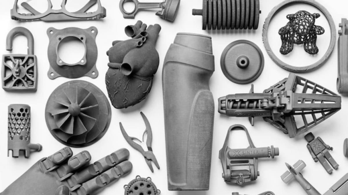
(Lead image source: Interesting Engineering)
License: The text of "3D Modeling for Printing: Best Practices" by All3DP is licensed under a Creative Commons Attribution 4.0 International License.