What Is an STL File? – The STL Format Simply Explained
What is an STL file? What does STL stand for? All that and more as we explain the origins, structure, and uses of the STL file format for 3D printing.
In a nutshell, an STL file stores information about 3D models. This format describes only the surface geometry of a three-dimensional object without representing color, texture, or other common model attributes.
These files are typically created by a computer-aided design (CAD) program as an end product of the 3D modeling process. You can identify STL files by the “.stl” file extension.
Here’s a primer on where they come from, what the file type contains, how they work, the advantages and disadvantages of their use, plus alternative file formats to consider.
What Is an STL File?
The STL file format is the most commonly used file format for 3D printing. When used with a 3D slicer, it allows a computer to communicate with the 3D printer hardware.
Since its humble beginnings, many CAD software packages have adopted and supported the STL file format. Today it is widely used for rapid prototyping, 3D printing, and computer-aided manufacturing. Hobbyists and professionals alike use it.
What Does STL Stand For?

Oddly, the true meaning of STL as an abbreviation is a point of contention for some. In our view, it can easily be traced back to a logical origin.
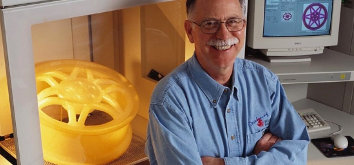
It’s widely believed that STL is an abbreviation of the word STereoLithography, a 3D printing process and corresponding file type created by Chuck Hull at 3D Systems in the 1980s. There are plausible sounding backronyms attached to the STL file type, including “Standard Triangle Language,” “Standard Tessellation Language,” and “Surface Tesselation Language.”
How Does the STL File Format Store a Model?
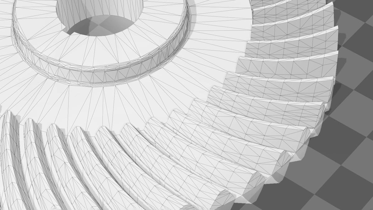
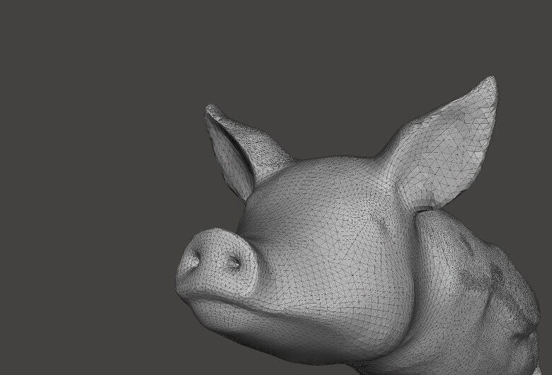
The primary purpose of the STL file format is to encode the surface geometry of a 3D object. It encodes this information using a simple concept called “tessellation.”
Tessellation
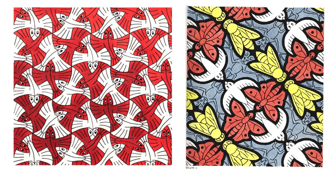
Tessellation is the process of tiling a surface with one or more geometric shapes so there are no overlaps or gaps. If you have ever seen a tiled floor or wall, that is an excellent example of tessellation.

Exploiting Tessellation to Encode Surface Data
In 1987, Chuck Hull, founder of 3D Systems, had just patented the stereolithographic printing process. Part and parcel of getting the process to work was figuring out a way to transfer information about 3D CAD models to the 3D printer, something the Albert Consulting Group achieved for 3D Systems when it realized it could use tessellations of the 3D model’s surface to encode this information.
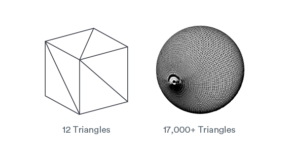
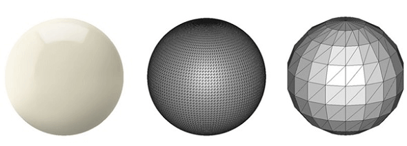
Let’s look at a few examples to understand how this works. For example, if you have a simple 3D cube, this can be covered by 12 triangles, as shown in the image below. As you can see, there are two triangles per face. Since the cube has six faces, it adds up to 12 triangles.
If you have a 3D model of a sphere, then it can be covered by many small triangles, also shown in the same image. Because the triangles always consist of three straight edges, the only way to approximate curved geometries is to increase mesh density and decrease the individual triangles’ size.
Differences Between ASCII and Binary STL
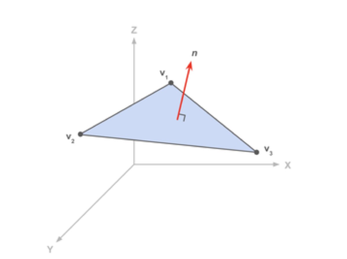
The STL file format provides two ways of storing information about the triangular facets that tile the object surface. These are called ASCII encoding and binary encoding. In both formats, the information of each triangle is stored as:
- The coordinates of the vertices.
- The components of the unit normal vector to the triangle. The normal vector should point outwards in accordance with the 3D model.
The ASCII STL File Format
The ASCII STL file starts with the mandatory line:
solid <name>
where <name> is the name of the 3D model. This field can be left blank, but there must be a space after the word “solid” in that case.
The file continues with information about the covering triangles. Information about the vertices and the normal vector is represented as:
facet normal nx ny nz
    outer loop
        vertex v1x v1y v1z
        vertex v2x v2y v2z
        vertex v3x v3y v3z
    endloop
endfacet
Here, n is the normal of the triangle, and v1, v2, and v3 are the triangle’s vertices. Coordinate values are represented as a floating-point number with the sign-mantissa-esign-exponent format – for example, “3.245000e-002”.
The file ends with the mandatory line:
endsolid <name>
The Binary STL File Format
The ASCII STL file can become huge if the tessellation involves many small triangles. This is why the more compact binary STL format exists.
The binary STL file starts with an 80-character header. This is generally ignored by most STL file readers, with some notable exceptions that we will talk about later. After the header, the total number of triangles is indicated using a 4-byte unsigned integer.
UINT8[80] – Header
UINT32 – Number of triangles
The information about the triangles follows. The file ends after the last triangle.
Twelve 32-bit floating-point numbers represent each triangle. Like the ASCII STL file, three numbers are for the 3D Cartesian coordinates of the triangle’s normal to the triangle. The remaining nine numbers are for the coordinates of the vertices (three each). Here’s how this looks:
for each triangle
REAL32[3] – Normal vector
REAL32[3] – Vertex 1
REAL32[3] – Vertex 2
REAL32[3] – Vertex 3
UINT16 – Attribute byte count
end
Note that after each triangle, there is a 2-byte sequence called the “attribute byte count.” This is usually set to zero and acts as a spacer between two triangles. But some software will use these 2 bytes to encode additional information about the triangle. We will see such an example later, where these bytes are used to store color information.
Special Rules for the STL File Format
The STL specification has some special rules for tessellation and storing information.
The Vertex Rule
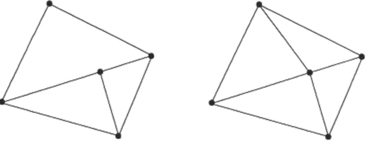
The vertex rule states that each triangle must share two vertices with its neighboring triangles.
This rule is to be respected when tessellating the surface of the 3D object.
According to this rule, here’s an example of a valid and invalid tessellation. The figure on the left violates this rule and is an invalid tessellation, while the figure on the right is conformant and valid.
The Orientation Rule
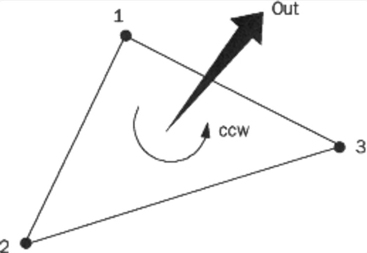
The orientation rule says that the orientation of the facet (i.e. which way is “in” the 3D object and which way is “out”) must be specified in two ways.
First, the direction of the normal should point outwards. Second, the vertices are listed in counterclockwise order when looking at the object from the outside (right-hand rule).
The All Positive Octant Rule
The all positive octant rule says that the coordinates of the triangle vertices must all be positive.
This implies that the 3D object lives in the all-positive octant of the 3D Cartesian coordinate system (and hence the name).
The rationale behind this rule is to save space. If the 3D object were allowed to live anywhere in the coordinate space, we would have to deal with negative coordinates. To store negative coordinates, you use signed floating-point numbers. Signed floating-point numbers require one extra bit to store the sign (+/-). By ensuring that all coordinates are positive, this rule allows us to use unsigned numbers for the coordinates and save a bit for every coordinate value we store.

The Triangle Sorting Rule
The triangle sorting rule recommends that the triangles appear in ascending z-value order.
This helps the software to slice the 3D models faster, but the rule is not strictly enforced.
How is an STL File 3D Printed?
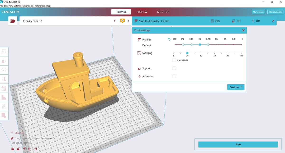
For 3D printing, you must open the STL file in slicing software, often known simply as a “slicer.” What’s a slicer? It’s a piece of 3D printing software that converts digital 3D models into printing instructions for your 3D printer to create an object.
Based on your chosen settings, the slicer chops up your STL file into hundreds (sometimes thousands) of flat horizontal layers and calculates how much material your printer will need to extrude and how long it will take.


All of this information is written into a G-code file, the native language of your 3D printer. Slicer settings impact your print quality, so having the right software and settings is essential to get you the best quality print possible.
Once the G-code is on your 3D printer, the machine follows the instructions in order. The separate two-dimensional layers are printed one by one to produce a three-dimensional object on your print bed.
Is Every STL File 3D Printable?
Unfortunately not. Only a 3D design specifically made for 3D printing is 3D printable. The STL file is just the container for the data, not a guarantee that something is printable.
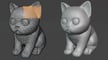
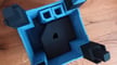
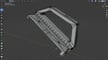
3D models suitable for 3D printing need a wall thickness that’s within the print resolution and “watertight” surface geometry. Even if a model is visible on a computer screen and looks like a three-dimensional object, there might be errors in the geometry that make it not solid or non-manifold, meaning that it cannot be folded into a 2D surface with all normals pointing in the same direction.
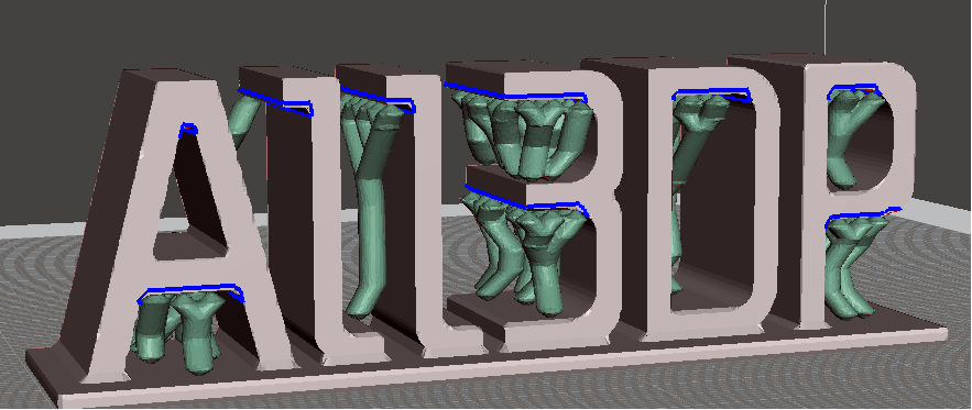
There’s also the consideration of overhanging elements in the model. Look at the ALL3DP logo in the picture above; if the model is printed upright, then overhanging elements with more than a 45-degree angle will require support structures (which you can see in green).
When downloading an STL file that you haven’t created yourself, it’s worth verifying that it is indeed 3D printable. This will save you a lot of time and frustration (and filament).
How to Optimize STL Files
The STL file format approximates the surface of a CAD model with triangles. The approximation is never perfect, and the facets introduce coarseness to the model.
Therefore, finding the right balance between file size and print quality is crucial. It does not make sense to reduce the size of the triangles ad infinitum because first, your eyes and then your printer’s resolution will be unable to distinguish between print qualities.
Most CAD software offers a couple of settings when exporting STL files. These settings control the facets’ size, hence print quality and file size. Let’s dig into the most critical settings and determine their optimum values.
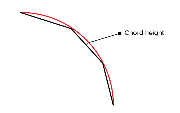
Chord Height or Tolerance
Most CAD software will let you choose a chord height or tolerance parameter. The chord height is the maximum distance from the surface of the original design and the STL mesh. If you select the proper tolerance, your prints will look smooth and not facetted. It’s pretty evident that the smaller the chord height, the more accurately the facets represent the actual surface of the model.
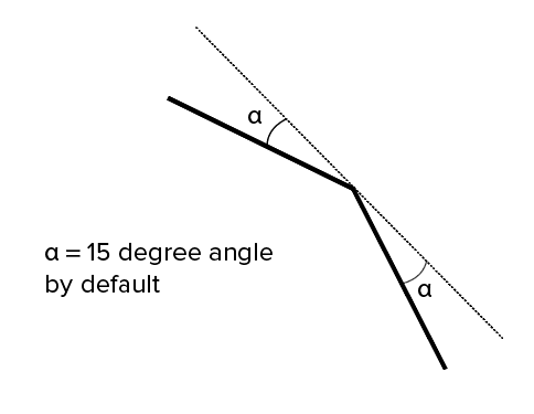
Angular Deviation or Angular Tolerance
Angular tolerance limits the angle between the normals of adjacent triangles. The default angle is usually set at 15 degrees. Decreasing the tolerance (to between 0 and 1) improves print resolution.
Binary or ASCII?
Finally, you can export the STL file in binary or ASCII format. The binary format is always recommended for 3D printing since it results in smaller file sizes. However, if you want to inspect the STL file for debugging manually, ASCII is preferable because it is easier to read.
STL File Alternatives
The STL file format is not the only format used in 3D printing. There are over 30 file formats for 3D printing. Most important is the OBJ file format, which can store color and texture profiles. Another option is the Polygon file format (PLY), initially used for storing 3D scanned objects.
More recently, there have been efforts to launch a new file type by The 3MF Consortium, proposing a new 3D printing file format called 3MF. They claim it will streamline and improve the 3D printing process.

Short for 3D Manufacturing Format, this open-source file extension contains further relevant information, including duplicates, printer profile settings, supports, layer heights, modifications, units, color, texture, and even a thumbnail.
Despite its benefits, it doesn’t seem to have gained enough traction to topple STL just yet as the 3D printing file type of convenience. Still, it has undoubtedly gained popularity over the years, with many 3D printer manufacturers offering it as their default scene file.
Advantages & Disadvantages
Since there are many 3D printing file formats, the obvious question is, “Which one should you use for your prints?” As it turns out, the answer depends a lot on your use case.
When Not to Use an STL File
As we saw earlier, the STL file format cannot store additional information such as color, material, facets, or triangles. It only stores information about the vertices and the normal vector. If you want to use multiple colors or materials for your prints, then the STL file format is not the right choice. The OBJ or 3MF formats are popular and well-supported formats that can specify color and material. Therefore, either is the right choice for this task.
When to Use an STL File
On the other hand, if you want to print with a single color or material, which is most often the case, STL is better than OBJ since it is more straightforward, leading to smaller file sizes and faster processing.
Advantages of the STL File Type
Universal: Another significant advantage of the STL file format is that it is universal and supported by nearly all 3D printers. This cannot be said for the OBJ format, even though it also enjoys reasonable adoption and support. The VRML, AMF, and 3MF formats are not as widely supported at this point.
Mature ecosystem: Most 3D printable models you can find online are in the STL file format. This ecosystem, combined with STL-based software investments made by 3D printer manufacturers, has given rise to a large user base heavily invested in the format. This means there’s plenty of third-party software dealing with STL files, which is not the case with the other file formats.
Disadvantages of the STL File Type
There are some glaring disadvantages to using STL as well.
Fidelity: As the fidelity of printing processes embraces micron-scale resolution, the number of triangles required to describe smooth curved surfaces can result in massive file sizes.
No metadata: It’s also impossible to include metadata (such as authorship and copyright information) in an STL file.
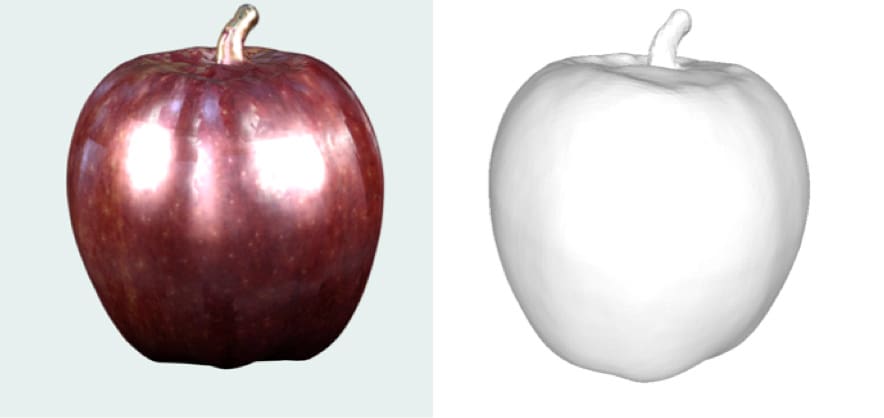
Color Printing with STL Files
In the last section, we said that the STL file format cannot handle multicolor models. The reason the STL file format lacks color information is simple. When rapid prototyping evolved in the 1980s, no one thought of color printing. Nowadays, 3D printing materials and processes have evolved rapidly. Some allow you to print in full color – think of sandstone 3D scans, as pictured above.
However, it’s unfair to say that STL cannot handle colors. It turns out that there are non-standard versions of the STL format that can carry color information.
For example, the VisCAM and Solidview software packages use the “attribute byte count” at the end of every triangle to store a 15-bit RGB color using the following system:
bits 0 to 4 for blue (0 to 31),
bits 5 to 9 for green (0 to 31),
bits 10 to 14 for red (0 to 31),
bit 15 is 1 if the color is valid, or 0 if the color is not valid (as with normal STL files).
On the other hand, the Materialise Magics software uses the 80-byte header in binary format to represent the overall color of the 3D object. The color is specified by including the ASCII string “COLOR=” followed by four bytes representing red, green, blue, and an alpha channel (transparency) in the range 0–255. This base color can also be overridden at each facet using the “attribute byte count” bytes.
STL File Resources
If you have this far, congratulations! You now know quite a bit about STL and can be called an STL file format expert.
In this final section, we will share some excellent software and resources that you can use for downloading, viewing, editing, and repairing STL files.
STL Downloads
There are many repositories, marketplaces, and search engines on the web containing millions of free STL files.

STL Viewers
Fortunately, opening an STL file is not too complicated. There are several free STL file viewers, which you can access online or as a desktop application.
STL Editors and Converters
Yes, it is entirely possible to edit an STL file and convert the STL file to another file format. Because the format is open, there is nothing to prevent you from changing the contents of a file. The process of editing is relatively easy.
STL Repair Software and Services
Remember the section where we discussed the rules that STL files must satisfy? For example, adjacent triangles must share two vertices and the right-hand rule applied to the vertices should result in the same orientation as the normal vector. If these conditions are violated in an STL file, it’s broken or corrupt.
There are several programs that can help with repairing a broken STL file. For example, Meshmixer is an excellent free tool for fixing the most common STL file problems.
In conclusion, we have learned how the STL file format encodes the layout of 3D models. We discussed how to optimize STL files for the best 3D printing quality. We talked about how the STL file format compares with the other popular 3D printing file format OBJ and when to use each of these formats. Finally, we shared some resources to download, view, edit, and repair STL files.
We hope that an in-depth understanding of the STL file format helps you become a more knowledgeable user of your 3D printer. If you found this article useful, share it with other 3D printing enthusiasts and spread the word. Do you have some questions or remarks? Let us know in the comments below!
License: The text of "What Is an STL File? – The STL Format Simply Explained" by All3DP is licensed under a Creative Commons Attribution 4.0 International License.